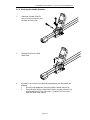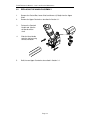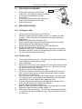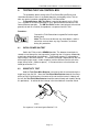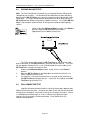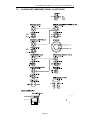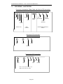
1
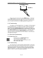
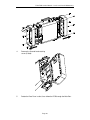
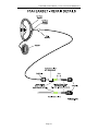
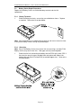
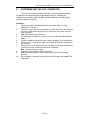
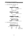
FIELD SERVICE MANUAL F1A4 Metal Mine Detector NSN 6665-66-142-9741 LEVEL 1 MAINTENANCE LEVEL 2 MAINTENANCE Date: 1st June, 2005 F1A4 Field Service Manual – Level 1 and Level 2 Maintenance Page 2 F1A4 Field Service Manual – Level 1 and Level 2 Maintenance WARNING THIS DOCUMENT CONTAINS MINELAB ELECTRONICS LIMITED RIGHTS TECHNICAL DATA OR RESTRICTED RIGHTS DATA OR BOTH. Minelab Electronics This work is copyright. Apart from any use as permitted under the Copyright Act 1968, no part may be reproduced by any process without written permission from Minelab Electronics 118 Hayward Avenue, Torrensville South Australia.5031 CONTENTS SECTION PAGE 1. Introduction ...................................................................................................................5 1.1 Levels of Maintenance ............................................................................................5 1.2 How to use this Manual ...........................................................................................5 Level 1 Maintenance ..............................................................................................................6 2. Mechanical and Functional Testing of the F1A4 ................................................................7 2.1 Mechanical Testing .................................................................................................7 2.2 Functional Testing...................................................................................................8 3. Maintenance Procedures .................................................................................................11 3.1 Camlock Repair Procedures .................................................................................11 3.2 Replacing the Handle Assembly............................................................................14 3.3 Replacing the Handgrip.........................................................................................15 3.4 Replacing the Coil .................................................................................................15 Level 2 Maintenance ............................................................................................................16 4. Testing the F1A4 Control Box..........................................................................................17 4.1 Initial Power On Test .............................................................................................17 4.2 Sensitivity Test ......................................................................................................17 4.3 Ground Balance Test ............................................................................................18 4.4 Coil Connector Test ..............................................................................................18 4.5 Noise Cancel test ..................................................................................................19 4.6 Audio Reset Test...................................................................................................19 4.7 Earset Test............................................................................................................19 5. Troubleshooting and Repair of the F1A4 Control Box ......................................................20 5.1 Troubleshooting the F1A4 Control Box..................................................................20 5.2 F1A4 Control Box and Earset Repair Procedures .................................................24 6. Reterminating the Coil Connector ....................................................................................33 7. F1A4 Control Box Internal Connection Details .................................................................34 7.1 PCB to Front Panel Connections – List .................................................................34 7.2 PCB to Rear Panel Connections – List..................................................................34 7.3 Plug/Socket/Component wiring – Illustration .........................................................35 7.4 PCB wiring – Illustration ........................................................................................36 F1A4 Field Service Manual – Level 1 and Level 2 Maintenance 1. INTRODUCTION This manual is intended to instruct service technicians in functional testing and Levels 1 and 2 maintenance of the F1A4 mine detector. All sub-assemblies of the F1A4 can be replaced without the need for adjustment or calibration. This service manual includes all Level 1 and Level 2 maintenance procedures, including functional testing and troubleshooting. 1.1 LEVELS OF MAINTENANCE Levels of maintenance for the F1A4 comprise: Level 1 maintenance includes repair and/or replacement of all major Level 1: components of the detector. This level of maintenance can be conducted at demining field sites or local depots if required. Level 1 maintenance includes full functional testing of the detector and does not require any special test equipment or facilities. Level 2 maintenance encompasses Level 1 maintenance plus coil reLevel 2: termination and basic repairs to the F1A4 control box and earset. This level of maintenance requires electronic workshop facilities. Level 3 maintenance encompasses Level 1 and Level 2 maintenance, Level 3: plus control box printed circuit board repair. Level 3 repairs are only conducted at Minelab's repair workshops located in Australia, Ireland and the USA. 1.2 HOW TO USE THIS MANUAL This manual is divided into Level 1 and Level 2 maintenance sections. If doubt exists as to the serviceability or mechanical integrity of the F1A4, turn to Section 2 for a comprehensive mechanical and functional test of the F1A4. If any mechanical component (eg handgrip, coil) of the F1A4 requires replacement, turn to Level 1 maintenance procedures in Section 3, which details all mechanical repairs. All repairs to the F1A4 Control Box, and Coil retermination procedures, are in the Level 2 Maintenance Procedures, beginning at Section 4. Page 5 F1A4 Field Service Manual – Level 1 and Level 2 Maintenance LEVEL 1 MAINTENANCE Page 6 F1A4 Field Service Manual – Level 1 and Level 2 Maintenance 2. MECHANICAL AND FUNCTIONAL TESTING OF THE F1A4 This section details mechanical and functional testing of the F1A4. Section 2.1 lists all mechanical testing and directs the user to applicable Level 1 repair procedures if any defects are found. Section 2.2 lists functional testing of the F1A4 and will refer the user to the applicable fault finding procedure if a fault is found. A defective component is confirmed using the substitution method, so a complete and fully serviceable F1A4 should be on hand. After any repair to the F1A4, Section 2.2 Functional Testing, must be completed in full to ensure the F1A4 is returned for operational use. 2.1 MECHANICAL TESTING To conduct mechanical testing, unpack and fully assemble the F1A4 (As described in the F1A4 Operations Manual). Ensure the armrest is fitted, control box is mounted on the shaft and good batteries are used. During assembly: 1. Check that the coil yoke nut and bolt are firmly tightened and that the friction washers are present and in good condition. The coil should be held firmly in position (but moveable) on the yoke. If coil is loose on the yoke check the nut, bolt and friction washers and replace as required. 2. Check that the skid plate is firmly attached, is not worn through or cracked. Replace if required. 3. Check that the upper shaft slides smoothly over the lower shaft and when the camlock is closed the upper shaft stays in position on the lower shaft. If necessary, replace the camlock (Section 3.1). 4. Inspect the Armrest for cracks and other damage. Inspect the armstrap. Check that the armrest slides fully into the upper shaft and is held firmly when the upper camlock is closed. If necessary, replace the camlock (Section 3.1). 5. Check that the control box is firmly attached when the lock pin is fully rotated to the stop. If necessary replace the handle (Section 3.2). 6. Inspect the handstrap and hand grip for wear, and replace if necessary (Section 3.3). Page 7 F1A4 Field Service Manual – Level 1 and Level 2 Maintenance 2.2 FUNCTIONAL TESTING This section details functional testing of the F1A4. It should be used to confirm serviceability of an F1A4 before it is returned to the field for use and whenever doubt exists about the serviceability of an F1A4. The F1A4 must pass all these tests to be considered serviceable. Remedial action is included for repair if required. If remedial action is completed (ie the F1A4 is repaired using these procedures), the full functional test should be repeated from Section 2.2.1. A Ground Balance (GB) Test Piece is required to properly test the F1A4. This is needed to simulate mineralised or “noisy” ground and ensure correct F1A4 Ground Balance operation. The GB Test Piece can be a local piece of mineralised ground (hot rock or a fired tile) that produces a response from the F1A4. Procedure: Ensure the coil connector ‘clicks’ in to the socket. If the coil plug does not ‘click’ in, replace the coil plug washer, if the coil plug still does not ‘click’ in, send the coil to an accredited F1A4 Level 2 maintenance workshop. Note: The Coil must not be near any metal objects, and the technician must not wear any rings, bracelets, or watches during this procedure. 2.2.1 Initial Power On Test Switch the F1A4 on to the Search position. The detector should take six seconds to run through the start up routine, comprising four rising tones followed by a continuous background threshold tone. F1A4 target response is indicated by a clear change in the threshold tone. The amount of change is dependent on the size of the target (larger target – louder response) and the distance from the coil to the target (closer to coil – louder response). If the correct tones or threshold are not heard the faulty control box (or battery carrier) should be replaced or the F1A4 should be sent to an accredited F1A4 Level 2 maintenance workshop. 2.2.2 Sensitivity Testing Hold the Test Piece Mine Detector in one hand, with the end containing the target away from the Coil. Move the Test Piece Mine Detector towards the centre of the coil until it lightly touches the centre of the coil and then move it sideways off the coil (the Test Piece Mine Detector should be moved slowly and smoothly during this procedure). A soft but distinct change in the threshold tone should be heard. P0263-B If a response is not heard replace the faulty Control Box (or Coil, see Section 3.4) or the F1A4 should be sent to an accredited F1A4 Level 2 maintenance workshop for repair. Page 8 F1A4 Field Service Manual – Level 1 and Level 2 Maintenance 2.2.3 Ground Balance Testing Note: The F1A4 Control Box will memorise its last Ground Balance settings when switched off and then on again. If a Control Box/Coil combination has been previously balanced to the GB Test Piece, on re-testing, a response to that hot rock will not be heard again. The same Control Box/Coil combination must be rebalanced with a GB Test Piece with different characteristics before re-testing. (If a suitable GB Test Piece is not available, a piece of ferrite or local ground around the workshop may suffice.) While holding the Off/Search/Balance switch in the Balance position, move the GB Test Piece up and down, approximately 25 to 100 mm from the Coil. Note: For the first five seconds when the Off/Search/Balance switch is switched to the Balance position, the F1A4 will ground balance at a fast rate, after this time the F1A4 will continue to balance but at a much slower rate. Consequently, if the F1A4 has not completely balanced out the GB Test Piece within five seconds, release the Off/Search/Balance switch to the Search position and reselect the Balance position. The F1A4 should initially detect the GB Test Piece (a change of threshold tone will be heard) as the GB Test Piece is moved to and from the Coil. The F1A4 will then become “balanced” to it, i.e. the F1A4 threshold will remain stable as the GB Test Piece is moved to and from the Coil. To confirm that the F1A4 has ‘balanced’ correctly: 1. Release the Off/Search/Balance switch so that it returns to the Search position. 2. Move the GB Test Piece as described above and confirm that there is no further response from the F1A4. 3. If a response is still heard, check that there is no metal on the technician or the GB Test Piece and repeat the test. If the F1A4 still responds to the GB Test Piece, the faulty Control Box or Coil, (Section 3.4) should be replaced or the F1A4 should be sent to an accredited F1A4 Level 2 maintenance workshop for repair. Page 9 F1A4 Field Service Manual – Level 1 and Level 2 Maintenance 2.2.4 Coil Connector Test Loop the coil cable and hold against side of the control box, approximately 250mm from the coil connector. Grasp the coil cable 75mm from the coil connector and gently turn 30 degrees side to side, listening for a change of threshold. If there is a noticeable threshold change (ie similar in volume to test piece threshold change), the Coil should be replaced (Section 3.4) or the F1A4 should be sent to an accredited F1A4 Level 2 maintenance workshop for repair. 2.2.5 Noise Cancel Test Momentarily press the NOISE CANCEL button. The F1A4 should immediately “beep”. After 70 seconds the F1A4 should “beep” four times: BEEP BEEP BEEP BEEP If the correct tones are not heard the faulty Control Box should be replaced or the F1A4 should be sent to an accredited F1A4 Level 2 maintenance workshop for repair. 2.2.6 Audio Reset Test Momentarily press the AUDIO RESET button. The F1A4 should immediately BEEP. After 3 seconds the F1A4 should give five “high / low” beeps: BEEP BEEP BEEP BEEP BEEP The threshold tone level should now be set at the correct operating level (ie just audible). If the correct tones or threshold level are not heard the faulty Control Box should be replaced or the F1A4 should be sent to an accredited F1A4 Level 2 maintenance workshop for repair. 2.2.7 Earset Test 1. 2. 3. Connect the Earset to the Control Box and ensure that the threshold tone is audible at the earphone. If a volume control is fitted, ensure that it operates correctly. If the Earset does not operate correctly it should be replaced or the F1A4 should be sent to an accredited F1A4 Level 2 maintenance workshop for repair. Page 10 F1A4 Field Service Manual – Level 1 and Level 2 Maintenance 3. MAINTENANCE PROCEDURES This section details mechanical maintenance procedures and covers the following: 1. Camlock repair procedures (Section 3.1) 2. Handle replacement procedures (Section 3.2) 3. Hand grip replacement procedure (Section 3.3) 4. Coil replacement procedure (Section 3.4) 3.1 CAMLOCK REPAIR PROCEDURES This procedure details the dismantling and re-assembly of the Camlocks fitted to the Upper Shaft of the F1A4. This is only necessary when a Camlock becomes damaged or worn. The F1A4 uses Camlocks in three locations – Upper Camlock locks the armrest into the Upper shaft, Lower Camlock locks the lower shaft into the Upper shaft and the Handle camlock locks the Handle onto the Upper shaft. Camlock kits are available to renew their locking capability - they are easily and cost effectively serviced using the following procedures. These procedures should also be used to remove and refit camlocks when replacing a coil. Procedure: fitted) Remove the Control Box, Lower shaft, and Armrest from the Upper Shaft (if Identify the Camlock to be replaced or serviced: Note: The Upper and Lower Camlocks use different Pressure Blocks. Refer to the figure above to ensure that you have the correct service kit for the Camlock to be serviced. Each kit contains all the components for servicing a particular Camlock: 1. 8008-0012 Service Kit Camlock Upper 2. 8008-0013 Service Kit Camlock Lower 3. 8008-0014 Service Kit Camlock Handle Page 11 F1A4 Field Service Manual – Level 1 and Level 2 Maintenance 3.1.1 Servicing the Upper and Lower Camlocks 1. Knock out Camlock Pivot Pin with the 3 to 3.5mm punch. 2. Remove Cam Lever from the Camlock Body. 3. Remove Pressure Block from the Camlock Body. 4. Slide the Camlock Body from the shaft. 5. Assembly is the reverse of the dismantling procedure, with attention to the following: 1. use only new components from the appropriate Camlock Service Kit, 2. press the Stainless Steel Wear Plate firmly into the Pressure Block, and 3. ensure that the correct Pressure Block is used at the correct end. Note: The Pressure Block End Views (at right) should help the identification process. Page 12 F1A4 Field Service Manual – Level 1 and Level 2 Maintenance 3.1.2 Servicing the Handle Camlock 1. Knock out Camlock Pivot Pin with the 3 to 3.5mm punch and Remove the Cam Lever. 2. Remove the Stainless Steel Wear Plate, 3. Assembly is the reverse of the dismantling procedure, with attention to the following: 1. Use only new components from the Handle Camlock Service Kit. 2. Ensure that the Stainless Steel Wear Plate is correctly seated in the Handle Moulding until the Cam Lever is installed. The Cam Lever holds the Wear Plate in place. Page 13 F1A4 Field Service Manual – Level 1 and Level 2 Maintenance 3.2 REPLACING THE HANDLE ASSEMBLY 1. Remove the Control Box, Lower Shaft and Armrest (if fitted) from the Upper Shaft. Remove the Upper Camlock as described in Section 3.1. 2. 3. Release the Camlock Handle and slide the old Handle off the shaft. 4. Slide the New Handle onto the shaft ensuring correct orientation. 5. Refit the new Upper Camlock as described in Section 3.1. Page 14 F1A4 Field Service Manual – Level 1 and Level 2 Maintenance 3.3 REPLACING THE HANDGRIP 1. 4. Remove the hand strap from the handle (refer to the ‘F1A4 Operations Manual if required). Cut the foam hand-grip down its length and remove it. Using water, wet the handle and the foam and slide the foam hand-grip onto the handle. Refit the hand strap. 3.4 REPLACING THE COIL 2. 3. 3.4.1 To Remove a Coil: 1. 2. 3. 4. 5. 6. 7. 8. Carefully remove the dust cap from the Coil Plug. Remove the Upper Camlock Assembly (Section 3.1) and open the Lower Camlock. (This will allow the Coil Connector to easily pass through the Upper Shaft.) Withdraw the cable through the Upper Shaft. Starting from the upper end, pull the cable from the channel in the Lower Shaft and then from the cable clamp in the yoke. Remove the black wing-nut and bolt from the Coil-to-Shaft joint. Remove the friction washers from the Coil. Remove the Skid Plate. The Skid plate can be levered from the Coil with a flat bladed screwdriver, taking care not to damage the Coil or the Skid Plate. The coil is now free from the Lower Shaft. 3.4.2 To Refit a Coil: 1. 2. 3. 4. 5. 6. 7. 8. 9. 10. Fit the friction washers to the coil. Ensure that the four legs on each washer are pushed fully into their respective holes. Refit the Skid Plate. Hold the new Coil on a flat surface, position the Lower Shaft correctly around the coil top, insert the nylon bolt and attach the nut. Tighten the nut so that the coil can still pivot, but is not loose. Dampen the cable and cable groove with water. Starting at the lower end of the cable, and with the Shaft at 90° to the Coil face, use your thumbs to press the cable into the cable clamp in the black plastic yoke on the Lower Shaft. With your thumbs, press the cable into the cable groove in the Lower Shaft, ensuring that there is some free play in the cable between the Coil and the cable clamp. (The Shaft should still be at 90deg to the coil). Slide the Connector and cable through the Upper Shaft, starting from the Lower end, (the end with the Camlock still in position). Draw the cable up through the Upper Shaft. Note: The cable is to be drawn through, rather than trying to push it through. Replace the Upper Camlock Assembly (Section 3.1). Refit the dust cap to the Coil plug. (The dust cap should be moistened with a small amount of water to facilitate this step, ensure that no moisture enters the coil plug.) Page 15 F1A4 Field Service Manual – Level 1 and Level 2 Maintenance LEVEL 2 MAINTENANCE Page 16 F1A4 Field Service Manual – Level 1 and Level 2 Maintenance 4. TESTING THE F1A4 CONTROL BOX This procedure details testing of the F1A4 Control Box and Earset, and should be carried out if there is any doubt about the serviceability of the F1A4, or after any repairs have been completed to the F1A4 Control Box. A Ground Balance (GB) Test Piece is required to properly test the F1A4. This is needed to simulate mineralised or ‘noisy’ ground and ensure correct F1A4 Ground Balance operation. The GB Test Piece can be a local piece of mineralised ground (hot rock or a fired tile) that produces a response from the F1A4. Procedure: Connect the F1A4 Control box to a good Coil and charged battery pack. Note: The Coil must not be near any metal objects, and the technician must not wear any rings, bracelets, or watches during this procedure. 4.1 INITIAL POWER ON TEST Switch the F1A4 on to the SEARCH position. The detector should take six seconds to run through the start up routine, comprising four rising tones followed by a continuous background threshold tone. F1A4 target response is indicated by a clear change in the threshold tone. The amount of change is dependent on the size of the target (larger target – louder response) and the distance from the coil to the target (closer to coil – louder response). If the correct tones or threshold are not heard go to Section 5.1.1. 4.2 SENSITIVITY TEST Hold the Test Piece Mine Detector in one hand, with the end containing the target away from the Coil. Move the Test Piece Mine Detector towards the centre of the coil until it lightly touches the centre of the coil and then move it sideways off the coil (the Test Piece Mine Detector should be moved slowly and smoothly during this procedure). A soft but distinct change in the threshold tone should be heard. P0263-B If a response is not heard, go to Section 5.1.2. Page 17 F1A4 Field Service Manual – Level 1 and Level 2 Maintenance 4.3 GROUND BALANCE TEST Note: The F1A4 Control Box will memorise its last Ground Balance settings when switched off then on again. If a Control Box/Coil combination has been previously balanced to the GB Test Piece, on re-testing, a response to that hot rock will not be heard again. The same Control Box/Coil combination must be re-balanced with a GB Test Piece with different characteristics before re-testing. (If a suitable GB Test Piece is not available, a piece of ferrite or local ground around the workshop may suffice.) While holding the Off/Search/Balance switch in the Balance position, move the GB Test Piece up and down, approximately 25 to 100mm from the Coil. The F1A4 should initially detect the GB Test Piece (a change of threshold tone will be heard) as the GB Test Piece is moved to and from the Coil. The F1A4 will then become “balanced” to it, i.e. the F1A4 threshold will remain stable as the GB Test Piece is moved to and from the Coil. 1. Release the Off/Search/Balance switch so that it returns to the Search position. 2. Move the GB Test Piece as described above and confirm that there is no further response from the F1A4. 3. If a response is still heard check that there is no metal on the technician or the GB Test Piece and repeat the test. If the F1A4 still responds to the GB Test Piece, go to Section 5.1.3 4.4 COIL CONNECTOR TEST Loop the coil cable and anchor against side of the control box, approximately 250mm from the coil connector. Grasp the coil cable 75mm from the coil connector and gently turn 30 degrees side to side, listening for a change of threshold. If there is a noticeable threshold change (ie similar in volume to test piece threshold change), the coil connector is to be reterminated. Go to Section 6 for Coil Retermination procedure. Page 18 F1A4 Field Service Manual – Level 1 and Level 2 Maintenance 4.5 NOISE CANCEL TEST Momentarily press the NOISE CANCEL button. The F1A4 should immediately “beep” After 70 seconds the F1A4 should “beep” four times: BEEP BEEP BEEP BEEP If the correct tones are not heard, go to Section 5.1.4 4.6 AUDIO RESET TEST Momentarily press the AUDIO RESET button. The F1A4 should immediately BEEP. After 3 seconds the F1A4 should give five “high / low” beeps: BEEP BEEP BEEP BEEP BEEP The threshold tone level should now be set at the correct operating level (ie just audible). If the correct tones or threshold level are not heard, go to Section 5.1.5 4.7 EARSET TEST Connect the Earset to the Control Box and ensure that the threshold tone is audible at the earphone. If a volume control is fitted, ensure that it operates correctly. If the Earset does not operate correctly, go to Section 5.1.6. Page 19 F1A4 Field Service Manual – Level 1 and Level 2 Maintenance 5. TROUBLESHOOTING AND REPAIR OF THE F1A4 CONTROL BOX This section covers troubleshooting and repair of the F1A4 Control Box, required after Section 4 testing. After any repair has been completed, return to Section 4 for a complete test of the F1A4 Control Box. 5.1 TROUBLESHOOTING THE F1A4 CONTROL BOX 5.1.1 Initial Power On Troubleshooting 5.1.1.1 Power On Test Procedure Connect the F1A4 to a good Coil and charged battery pack. Note: The Coil must not be near any metal objects, and the technician must not wear any rings, bracelets, or watches during this procedure. Switch the F1A4 on to the Search position. The detector should take 6 seconds to run through the start up routine, comprising four rising tones, followed by a continuous background threshold tone. If the tones or threshold tone are distorted, the loud speaker maybe defective. Go to 5.2.1 for the loudspeaker replacement procedure. If there are still no tones or threshold, ensure that the batteries and battery carrier are good (if in doubt, substitute known good batteries and/or battery carrier). If there are still no tones or threshold tone, connect an Earset. If tones or the threshold tone are now heard through the Earset go to 5.1.1.2. If no tones or threshold are heard through the Earset go to 5.1.1.3. 5.1.1.2 Audio Troubleshooting Remove the 6 screws from the front panel and pull the front panel away from the case. Desolder the 2 wires from loudspeaker. With a multimeter, measure resistance of loudspeaker. Resistance should read approximately 15 ohms. If the resistance reading is incorrect, the loudspeaker is defective, go to 5.2.1 for the loudspeaker replacement procedure. If the resistance is OK, check wiring from the PCB to the speaker and earset jack and repair as necessary. If the wiring if found to be OK, the PCB is defective. Go to 5.2.4 for the PCB replacement procedure. 5.1.1.3 Off/Search/Balance Switch Troubleshooting Remove the 6 screws from the front panel and pull the front panel away from the case. With a multimeter, measure the circuit of the Off/Search/Balance switch (refer Section 7 for switch circuit details). If the switch does not measure correctly, the switch is defective, go to 5.2.2 for the Off/Search/Balance switch replacement procedure. If the switch measures OK, check wiring from the PCB to the Off/Search/Balance switch and Power Plug and repair as necessary. If the wiring if found to be OK, the PCB is defective. Go to 5.2.4 for the PCB replacement procedure. Page 20 F1A4 Field Service Manual – Level 1 and Level 2 Maintenance 5.1.2 Sensitivity Troubleshooting 5.1.2.1 Sensitivity Test Procedure Hold the Test Piece Mine Detector in one hand, with the end containing the target away from the Coil. Move the Test Piece Mine Detector towards the centre of the coil until it lightly touches the centre of the coil and then move it sideways off the coil (the Test Piece Mine Detector should be moved slowly and smoothly during this procedure). A soft but distinct change in the threshold tone should be heard. P0263-B 5.1.2.2 Troubleshooting If a response is not heard whilst moving the Test Piece Mine Detector across the Coil, replace the Coil. If a response is still not heard, remove the 6 screws from the front panel, pull the front panel away from the case, and check the wiring to the PCB from the Front Panel and repair as necessary. If the wiring if found to be OK, the PCB is defective. Go to 5.2.4 for the PCB replacement procedure. 5.1.3 Ground Balance Troubleshooting 5.1.3.1 Ground Balance Test Procedure While holding the Off/Search/Balance switch in the Balance position, move the GB Test Piece up and down, approximately 25 to 100mm from the Coil. The F1A4 should initially detect the GB Test Piece (a change of threshold tone will be heard) as the GB Test Piece is moved to and from the Coil. The F1A4 will then become “balanced” to it, i.e. the F1A4 threshold will remain stable as the GB Test Piece is moved to and from the Coil. Page 21 F1A4 Field Service Manual – Level 1 and Level 2 Maintenance Release the switch so that it returns to the SEARCH position. Continue to move the GB Test Piece up and down, approximately 25 to 100mm from the Coil. The F1A4 should not respond to the test piece. If a response is heard check that there is no metal on the technician or the GB Test Piece and repeat the test. 5.1.3.2 Troubleshooting If a response is still heard repeat the test. If a response is still heard, replace the coil and repeat the test. If a response is still heard, remove the 6 screws from the front panel, pull the front panel away from the case, and use a multimeter to check the circuit of the Off/Search/Balance switch (refer Section 7 for switch circuit details). If the switch does not measure correctly, the switch is defective, go to 5.2.2 for the Off/Search/Balance switch replacement procedure. If the switch measures OK, check wiring from the PCB to the Off/Search/Balance switch and repair as necessary If the wiring if found to be OK, the PCB is defective. Go to 5.2.4 for the PCB replacement procedure. 5.1.4 Noise Cancel Troubleshooting 5.1.4.1 Noise Cancel Test Momentarily press the NOISE CANCEL button. The F1A4 should immediately “beep”. After 70 seconds the F1A4 should “beep” four times: BEEP BEEP BEEP BEEP 5.1.4.2 Troubleshooting If the correct tones are not heard during the above procedure, remove the 6 screws from the front panel, pull the front panel away from the case, and check the wiring from the PCB to the Front Panel and repair as necessary (also check the ribbon cable for continuity). If there are still no tones, go to 5.2.5 for Front Panel replacement procedure. If the Front Panel has already been replaced the PCB is defective. Go to 5.2.4 for the PCB replacement procedure. Page 22 F1A4 Field Service Manual – Level 1 and Level 2 Maintenance 5.1.5 Audio Reset Troubleshooting 5.1.5.1 Audio Reset Test Momentarily press the AUDIO RESET button. The F1A4 should immediately BEEP. After 3 seconds the F1A4 should give five “high / low” beeps: BEEP BEEP BEEP BEEP BEEP The threshold tone level should now be set at the correct operating level (ie just audible). 5.1.5.2 Troubleshooting If the correct tones are not heard during the above procedure, remove the 6 screws from the front panel, pull the front panel away from the case, and check the wiring from the PCB to the Front Panel and repair as necessary (also check the ribbon cable for continuity). If there are still no tones, go to 5.2.5 for Front Panel replacement procedure. If the Front Panel has already been replaced the PCB is defective. Go to 5.2.4 for the PCB replacement procedure. 5.1.6 Earset Troubleshooting Determine, by physical inspection or resistance testing, whether the fault lies with the four pin connector, earphone or volume control (if fitted): 1. If the four pin connector requires replacement or retermination, go to 5.2.6.1. 2. If the earphone requires replacement or retermination, go to 5.2.6.2. 3. If the volume control is defective, repair or replace it, Section 5.2.6 is a guide to earphone repair procedures. Page 23 F1A4 Field Service Manual – Level 1 and Level 2 Maintenance 5.2 F1A4 CONTROL BOX REPAIR PROCEDURES This section covers individual F1A4 Control Box repair procedures required after Section 5.1 Troubleshooting. After any repair has been carried out, return to Section 4 for a complete functional test of the F1A4 Control Box. 5.2.1 Loudspeaker Replacement 1. 2. 3. 4. 5. 6. 7. 8. Place F1A4 Control Box on an Anti-static mat, ensuring that the wrist strap is being worn and is firmly connected to the Anti-static mat. Remove the 6 screws from the front panel and pull the front panel away from the case. Desolder wires from Loudspeaker. With a sharp knife, carefully remove the glue holding the Loudspeaker to the Front Panel and remove the Loudspeaker. Position the new Loudspeaker and, using a hot glue gun, carefully run a bead of glue around the outside of the new Loudspeaker, ensuring that no glue gets into the Loudspeaker. Allow the glue to set. Resolder wires to Loudspeaker and refit Front Panel. Go to Section 4 to retest the F1A4 Control Box. 5.2.2 Off/Search/Balance switch replacement 1. 2. 3. 4. 5. 6. 7. 8. 9. 10. Place F1A4 Control Box on an Anti-static mat, ensuring that the wrist strap is being worn and is firmly connected to the Anti-static mat. Remove the 6 screws from the front panel and pull the front panel away from the case. Remove PCB from case (refer to 5.2.4 if required). Remove dust boot from Off/Search/Balance switch (hold the switch to prevent the switch and wiring from twisting). Desolder switch wires from PCB, noting their positions. Remove defective switch and position new switch. Refit dust boot whilst holding the switch, ensuring that the new switch is correctly oriented (momentary position to Balance). Solder wires of new Off/Search/Balance switch to PCB, ensuring that the wires are connected to the correct holes on the PCB (refer Section 7 if required). Refit PCB into case (refer 5.2.4 if required). Go to Section 4 to retest the F1A4 Control Box. 5.2.3 Not used. 5.2.4 Replacing the PCB Assembly 1. 2. 3. Place F1A4 Control Box on an Anti-static mat, ensuring that the wrist strap is being worn and is firmly connected to the Anti-static mat. Remove the 6 screws from the Front Panel and pull the Front Panel away from the case. Remove the 6 screws from the Rear Panel and pull the Rear Panel away from the case. Page 24 F1A4 Field Service Manual – Level 1 and Level 2 Maintenance 4. Remove the Ground Lead retaining screw (if fitted). 5. Rotate the Rear Panel so that it can follow the PCB through the Main Box. Page 25 F1A4 Field Service Manual – Level 1 and Level 2 Maintenance 6. Pull the Front Panel, PCB and Rear Panel out of the Main Box from the Front. 7. 8. Unplug the blue ribbon connector from the Front Panel. Desolder all the wires, at the PCB, from the coil plug, loudspeaker, switch and earset connector (note wiring/PCB connections). Remove the Front Panel from the PCB. Desolder all the wires, at the PCB, from the power connector (note wiring/PCB connections). Remove the Rear Panel from the PCB. Remove the new PCB set from its antistatic bag. Place the faulty PCB into the antistatic bag and package it for return to the 9. 10. 11. Page 26 F1A4 Field Service Manual – Level 1 and Level 2 Maintenance 12. 13. factory repair facility. Assembly is the reverse of the dismantling process, with attention to the following: 1. Ensure that the PCB is correctly orientated before fitting into case. The coil connector and power connector will be nearest the black mounting block and the power connector at the end with the clips. 2. When reconnecting the ribbon cable, ensure that there are two spare pins on the loudspeaker side and three spare pins on the earset jack side. Apply a spot of hot glue to the blue ribbon connector plug to hold it in place. 3. Refer Section 7 for PCB connections if required. 4. Replace gaskets with new gaskets if required.G Go to Section 4 to retest the F1A4 Control Box. Page 27 F1A4 Field Service Manual – Level 1 and Level 2 Maintenance 5.2.5 Front Panel Replacement 1. 2. 3. 4. 5. 6. 7. 8. 9. 10. Place F1A4 Control Box on an Anti-static mat, ensuring that the wrist strap is being worn and is firmly connected to the Anti-static mat. Remove the 6 screws from the Front Panel and pull the Front Panel away from the case. Remove PCB from the case (refer to 5.2.4 if required). Unplug the blue ribbon cable. Desolder all wires, at the PCB, from the coil plug, loudspeaker, switch and earset connector (note wiring/PCB connections). Separate the Front Panel from the PCB. With the new Front Panel in position, solder all the wires to the PCB (refer to Section 7 for PCB connections if required). Reconnect the ribbon cable (ensure that there are two spare pins on the loudspeaker side and three spare pins on the earset jack side). Apply a spot of hot glue to the blue ribbon connector plug to hold it in place. Refit the PCB into the case. Go to Section 4 to retest the F1A4 Control Box. Page 28 F1A4 Field Service Manual – Level 1 and Level 2 Maintenance 5.2.6 Earset Repair Procedures 5.2.6.1 Four Pin plug repair Refer to the illustration at end of this section. Parts required: Minelab PN 1. 2301-0013 2. 9501-0024 3. NA Qty one (if req’d) 1.5m (If req’d) 10mm 4. NA 98mm 5. 6. NA NA As Req’d As Req’d Description Four pin plug Earset cable Green heatshrink, 3.2mm, non-adhesive (Earset Speaker Off only) Black heatshrink, 4.8mm, non-adhesive (1 x 40mm, 1x 33mm, 1 x 25mm) Silver Solder Multi flux cored 60/40 solder Note: The plug may be fitted to a four pin socket during this procedure. Retermination Procedure: 1. Unscrew plug backshell 2. Remove and discard earset wire (with heatshrink) from within the backshell. The toothed metallic inner sleeve and rubber sleeve immediately inside the toothed metallic sleeve should be kept for re-use. 3. Desolder and discard wire remnants from plug. Ensure all old solder and all wire strands are removed from plug pins. Melt a small amount of fresh solder into plug pins. 4. Prepare cable as follows: Note: When removing outer insulation, care should be taken not to nick or cut the internal wires. a. Remove 10mm of the outer rubber sheath. b. Twist outer copper shield back to outer rubber sheath and tin with normal multi core solder. c. Remove 7mm of outer teflon coating from each stainless steel inner conductor. Twist both bared conductors together and tin with solder. If these wires do not take the solder easily, tin with silver solder. d. Trim inner conductor so that 2mm protrudes from the insulation, and trim tinned copper shield to same total length. 5. Slide the following, in strict order, onto the earset cable: a. Backshell; b. Toothed metallic inner sleeve (with its rubber sheath); then c. For Earset Speaker Off only: 10mm length of green 3.2mm heatshrink d. 40mm length of 4.8mm black non-adhesive heatshrink, then 33mm length of 4.8mm black non-adhesive heatshrink, then 25mm length of 4.8mm black non-adhesive heatshrink. e. Solder the inner conductors to Pin C and the copper shield to Pin D. Note: For Earset Speaker Off only a very short length of wire should be soldered to Pins A and D. 6. Slide the 25mm length of black 4.8mm heatshrink down to (but not over) the plug pins and heat to shrink. Repeat this procedure with the 33mm length of 4.8mm heatshrink and then with the 40mm length of 4.8mm heatshrink. 7. Slide the rubber sheath (with toothed inner sleeve) down the wire until the teeth on the inner sleeve engage the teeth at the back of the plug. Do not twist the rubber sheath/toothed inner sleeve over the heatshrink as damage to the soldered wires will result. The rubber sheath may bind on the heatshrink, to overcome this, moisten the heatshrink with a small amount of Page 29 F1A4 Field Service Manual – Level 1 and Level 2 Maintenance 8. 9. 10. water, contact cleaner or other water based lubricant, ensuring that no moisture gets on the soldered pins. Slide down the back shell over the toothed inner sleeve onto the plug and screw down all the way. The backshell may bind on the toothed inner sleeve, if so moisten the toothed inner sleeve with a minimal amount of contact cleaner or other water based lubricant, ensure that the top of the rubber sheath is also lubricated, and that excess does not leak down to the soldered pins. For Earset Speaker Off only slide the 10mm length of 3.2mm green heatshrink to within 10mm of the end of the black heatshrink and heat to shrink. Test the repaired Earset with a known serviceable F1A4 Control Box. 5.2.6.2 Earphone repair Retermination Procedure: 1. 2. 3. 4. 5. 6. Remove speaker from Earphone Housing by gently prying it out with a small screwdriver and desolder wiring if necessary. Remove cable grommet for reuse. Prepare cable as follows: Note: When removing outer insulation, care should be taken not to nick or cut the internal wires. a. Remove 7mm of the outer rubber sheath. b. Twist outer copper shield back to outer rubber sheath and tin with normal multi core solder. c. Remove 5mm of outer teflon coating from each stainless steel inner conductor. Twist both bared conductors together and tin with solder. If these wires do not take the solder easily, tin with silver solder. d. Trim inner conductor so that 3mm protrudes from the insulation, and trim tinned copper shield to same total length. Solder copper shield to one solder pad on the speaker and the inner conductors to the other solder pad. Use as little heat as possible as these solder pads are easily damaged. Polarity is not critical. Refit speaker into Earphone Housing carefully. It should easily ‘click’ in. Ensure that wiring sits evenly in the Earphone Housing cut out and is not caught between speaker and Earphone Housing. Push cable into channel around the inside of the Earphone Housing. Slide grommet up the cable and onto the Earphone Housing protrusion. Test the repaired Earset with a known serviceable F1A4 Control Box. Page 30 F1A4 Field Service Manual – Level 1 and Level 2 Maintenance Page 31 F1A4 Field Service Manual – Level 1 and Level 2 Maintenance 5.3 Battery Carrier Repair Procedures Repairs to the Battery Carrier are limited to battery terminal and wire link replacement. 5.3.1 Battery Terminals 1. Check the Battery terminals, ensure they are not broken or loose. Replace as required. Refer to the illustration below. Note: When desoldering, or resoldering these terminals, do not use excessive heat as the plastic Battery Carrier housing may be damaged. 5.3.2 Wire Links Note: Early F1A4 Battery Carriers have 4 wire links (or round rings) and later F1A4 Battery Carriers only have 2 wire links. Both types are fully interchangeable. 1. Check the wire links connecting the battery terminal PCBs to the main PCB. If these are the round ring type, desolder them and replace with 20mm links made of 0.4 or 0.45mm insulated PUR (enamelled copper wire). Refer to the illustration below: Page 32 F1A4 Field Service Manual – Level 1 and Level 2 Maintenance 6. RETERMINATING THE COIL CONNECTOR The F1A4 has specialised cables that require exacting soldering methods. To solder the coil cable to the plug a good quality liquid flux, soldering iron (temperature controlled at 420°C to 460°C of around 60 watts) and good quality multi-core solder are required Procedure: 1. Prepare the cable in accordance with the connection details in “Coax Connection” in Section 7. 2. Twist the screen wires into a neat bunch (i.e. ready for tinning), ensuring that the wires are not pulled too tightly as this will pull the wires from inside the outer insulation. 3. Apply some liquid flux to the bunch. 4. If a solder pot is available, tin the wires using the solder pot and proceed to Step 9. 5. Prime the soldering iron tip with some solder and apply the iron to the bunch. 6. When the flux is smoking well, apply some solder to the bunch and continue the iron heat. 7. When the flux has nearly burned away, the solder should have displaced the enamel on the wires and covered the bunch completely. Note: Do not use excess solder. 8. Repeat the tinning process for the centre wire. 9. Solder the pre-tinned wires into the connector using industry standard practices. 10. Re-assemble the connector and test the coil with a known serviceable F1A4 Control Box. Page 33 F1A4 Field Service Manual – Level 1 and Level 2 Maintenance 7. F1A4 CONTROL BOX INTERNAL CONNECTION DETAILS 7.1 PCB TO FRONT PANEL CONNECTIONS – LIST COIL SOCKET FRONT PANEL PIN A PIN B PIN B PIN A J2-A J2-B J2-C J2-D PCB RED BLACK WHITE or YELLOW BLUE HEADPHONE SOCKET FRONT PANEL PIN D PIN C PIN A PIN B J10-1 J10-2 J10-3 J10-4 PCB BLACK BLUE RED WHITE or YELLOW LOUDSPEAKER LOUDSPEAKER -NEGATIVE + POSITIVE J9-1 J9-2 PCB BLACK RED or WHITE OFF/SEARCH/BALANCE SWITCH SWITCH ON/SEARCH BALANCE COMMON 7.2 PCB J11-1 RED J11-2 BLUE J11-3 WHITE or YELLOW PCB TO REAR PANEL CONNECTIONS – LIST POWER AND ACCESSORY SOCKET REAR PANEL SOCKET PIN D PINA CASE OR REAR PANEL EARTH PIN B PIN C PIN E PIN F Page 34 PCB J1-D BLACK J1-A RED GROUND BLUE J1-B ORANGE J1-C RED J1-E WHITE or YELLOW J1-F BROWN or YELLOW F1A4 Field Service Manual – Level 1 and Level 2 Maintenance 7.3 PLUG/SOCKET COMPONENT WIRING - ILLUSTRATION Page 35 F1A4 Field Service Manual – Level 1 and Level 2 Maintenance 7.4 PCB WIRING - ILLUSTRATION Earset plug, Loudspeaker, Ribbon Cable and Switch to PCB connections BLACK BLACK BLUE RIBBON CABLE RED RED RED (ON/SEARCH) BLUE (BALANCE) YELLOW EARSET PLUG LOUD SPEAKER ON/OFF/GROUND BALANCE SWITCH Coil plug to PCB connections RED BLACK BLUE YELLOW Power plug to PCB connections ORANGE BLACK RED YELLOW (COMMON) WHITE RED BLUE – Connected via screw to case. (Only used in early series F1A4s) Page 36 YELLOW