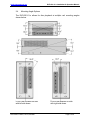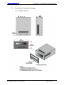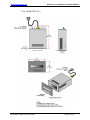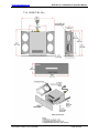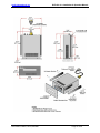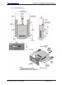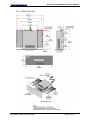
1
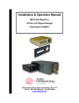
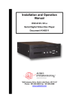
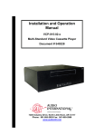
Installation and Operation
Manual
DVD-301-01-x
Digital Video Disc Player
Document # 540257
a DeCrane Aircraft Company
7300 Industry Drive, North Little Rock, AR 72117
Phone: 501-955-2929 Fax: 501-955-2988
www.audiointl.com
Audio International, Inc.
DVD-301-01-x Installation & Operation Manual
Document Revision History
Rev. Level
Date
Description
IR
01/2003
Initial Release
A
04/2004
Updated Power Wiring Requirements, removed Dolby
Digital Reference
B
08/2005
Updated IFR compatibility, added 'approx.' to weight
Reference Documents
Document #
Description
524561 Rev IR
DVD-301-01-x Outline Drawing
Service Bulletin List
Service
Bulletin #
Subject
Manual
Revision
Revision
Date
Table of Illustrations
Section #
Description
Page #
2.4
Mounting Angle Options
6
2.6
Typical System Block Diagram
8
4.1
Front Panel Controls
18
7.1
Reference Drawings
32
7.2.1-7.2.5
Cover Bezel Kit Installation Drawings
33-39
INFORMATION NOTICE: Despite any other copyright notice, this document and information
disclosed herein contains confidential, proprietary designs owned by Audio International, Inc.
Neither this document nor the data contained herein shall be reproduced, used, or disclosed to
anyone without the written authorization of Audio International, Inc.
Document # 540257, Rev B, 08/2005
Page 1 of 39
Audio International, Inc.
DVD-301-01-x Installation & Operation Manual
Table of Contents
Section
1.0
1.1
1.2
1.3
1.4
Description
General Information. . . . . . . . . . . . . . . . . . . . . . . . . . . . . . . . . . . . .
Introduction . . . . . . . . . . . . . . . . . . . . . . . . . . . . . . . . . . . . . . . . . . . .
Purpose of the Equipment . . . . . . . . . . . . . . . . . . . . . . . . . . . . . . . . .
Operational Features . . . . . . . . . . . . . . . . . . . . . . . . . . . . . . . . . . . . .
Optional Equipment . . . . . . . . . . . . . . . . . . . . . . . . . . . . . . . . . . . . . .
Page
3
3
3
4
4
2.1
2.2
2.3
2.4
2.5
2.6
Application. . . . . . . . . . . . . . . . . . . . . . . . . . . . . . . . . . . . . . . . . . . .
Typical Application . . . . . . . . . . . . . . . . . . . . . . . . . . . . . . . . . . . . . . .
Operating Parameters. . . . . . . . . . . . . . . . . . . . . . . . . . . . . . . . . . . .
Media and Format Capabilities. . . . . . . . . . . . . . . . . . . . . . . . . . . . . .
Mounting Options. . . . . . . . . . . . . . . . . . . . . . . . . . . . . .. . . . . . . . . .
Cover Bezel Compatibility. . . . . . . . . . . . . . . . . . . . . . . . . . . . . . . . . .
Typical System Block Diagram . . . . . . . . . . . . . . . . . . . . . . . . . . . . .
5
5
5
5
6
7
8
3.1
3.2
3.3
3.4
3.5
3.6
3.7
3.8
3.9
3.10
Installation. . . . . . . . . . . . . . . . . . . . . . . . . . . . . . . . . . . . . . . . . . . . .
Preparation. . . . . . . . . . . . . . . . . . . . . . . . . . . . . . . . . . . . . . . . . . . . .
Unpacking and Inspection. . . . . . . . . . . . . . . . . . . . . . . . . . . . . . . . .
Cautions & Warnings. . . . . . . . . . . . . . . . . . . . . . . . . . . . . . . . . . . . .
Wiring Requirements. . . . . . . . . . . . . . . . . . . . . . . . . . . . . . . . . . . . .
Physical Characteristics. . . . . . . . . . . . . . . . . . . . . . . . . . . . . . . . . . .
Clearance and Separation Requirements. . . . . . . . . . . . . . . . . . . . . .
Electrical Characteristics. . . . . . . . . . . . . . . . . . . . . . . . . . . . . . . . . .
Mating Connector Information. . . . . . . . . . . . . . . . . . . . . . . . . . . . . .
Pinout Assignments and Descriptions. . . . . . . . . . . . . . . . . . . . . . . .
Post Installation Test. . . . . . . . . . . . . . . . . . . . . . .. . . . . . . . . . . . . . .
9
9
9
10
11
13
13
14
15
15
16
4.1
4.2
4.3
Operation. . . . . . . . . . . . . . . . . . . . . . . . . . . . . . . . . . . . . . . . . . . . . .
Front Panel Controls. . . . . . . . . . . . . . . . . . . . . . . . . . . . . . . . . . . . . .
Front Panel Control Functions. . . . . . . . . . . . . . . . . . . . . . . . . . . . . .
Other Supported RS-485 and IR Commands. . . . . . . . . . . . . . . . . . .
18
18
19
25
5.1
5.2
5.3
5.4
Instructions for Continued Airworthiness. . . . . . . . . . . . . . . . . . .
Cleaning Method. . . . . . . . . . . . . . . . . . . . . . . . . . . . . . . . . . . . . . . . .
General Troubleshooting Procedures. . . . . . . . . . . . . . . . . . . . . . . .
Troubleshooting Chart. . . . . . . . . . . . . . . . . . . . . . . . . . . . . . . . . . . .
Airworthiness Limitations . . . . . . . . . . . . . . . . . . . . . . . . . . . . . . . . . .
29
29
29
30
30
6.0
Specifications. . . . . . . . . . . . . . . . . . . . . . . . . . . . . . . . . . . . . . . . . .
31
7.0
Reference Drawings. . . . . . . . . . . . . . . . . . . . . . . . . . . . . . . . . . . . .
32
2.0
3.0
4.0
5.0
Document # 540257, Rev B, 08/2005
Page 2 of 39
Audio International, Inc.
DVD-301-01-x Installation & Operation Manual
DVD-301-01-x
Digital Video Disc Player
1.0
General Information
1.1
Introduction
This manual contains information for the proper installation and operation
of Audio International’s (AI) Digital Video Disc Player, Model #
DVD-301-01-x. The “-x” suffix in the model number designates the type of
connector utilized; “-1” = Positronic and “-2” = D-Subminiature. Also
included are mechanical and electrical characteristics of the unit.
1.2
Purpose of the Equipment
Audio International’s DVD-301-01-x is a high-quality video disc player built
to support the navigation through and playback of DVD Video Discs. This
DVD player is designed with maximum shock isolation and an attractive
removable cover bezel. Additionally, the DVD-301-01-x supports all DVD
region codes for comprehensive international operation.
DVD-301-01-x can be mounted in a cabinet or bulkhead. A unique
strapping feature allows up to eight (8) similar devices to be used in the
same system at the same time, while maintaining independent control.
Optionally, a digital audio output is provided via a fiber optic interface to
allow input to audio processing modules such as a surround sound
processor.
For installation ease, the DVD-301-01-x is designed to be able to replace
specific previous versions of various Audio International DVD and VCP
players, regardless of current unit size, by the addition of cover bezel kits.
See Section 2.5, page 7, for details.
Document # 540257, Rev B, 08/2005
Page 3 of 39
Audio International, Inc.
1.3
DVD-301-01-x Installation & Operation Manual
Operational Features
Supports standard commercial audio CD and video DVD
Capability to channel stereo analog audio, DTS, and industry
standard Digital sound through PCM or provided fiber optic output
Supports all DVD region codes for international operation
NTSC-Only Video Output
Easy-to-use front panel controls
Optional infrared remote control capability
High fidelity, differential analog audio output
Up to 45 advanced functions available for AI's RC5 remote or any
AI data bus device for complete system customization
Full range (4 Hz to 20 kHz) frequency response
Eight (8) language and 32 subtitle options (dependent upon usersupplied disc capabilities)
Choice of camera viewing angles (dependent upon disc
capabilities)
Easy to mount and connect
2x, 4x, and 8x zoom and Pan for enhanced viewing
Compact, lightweight package
Five (5) Forward and Reverse accelerated scanning speeds with
DVD video
Four (4) slow forward and reverse speeds with DVD video
Internal test signal generation for convenient device validation,
system set-up, and system troubleshooting
1.4
Optional Equipment
The DVD-301-01-x is optionally controlled by AI infrared remote or touch
screen panels, and it is important to remember that some remote controls
possess functions not duplicated by the unit’s front panel buttons, such as
Menu and Set-Up. While the DVD-301-01-x is a complete and fully
functional standalone DVD Player, it is strongly recommended that a
remote control device also be employed for thorough enjoyment of the
unit.
Audio International also offers a wide variety of monitors, speakers,
headphone jacks, video distribution devices, and other equipment that will
perfectly complement the DVD-301-01-x and will also be valuable and
attractive additions to any cabin interior.
Contact your AI representative for details.
Document # 540257, Rev B, 08/2005
Page 4 of 39
Audio International, Inc.
2.0
DVD-301-01-x Installation & Operation Manual
Application
2.1
Typical Application
The DVD-301-01-x video input typically interfaces with a video monitor or
video distribution device (i.e., AV-3232, VSS-0408, etc.). Additionally, the
DVD-301-01-x is capable of providing audio output to various audio
distribution devices (i.e., AV-3232, AI-LDC101, HDM-3 etc.) Video Input
format is Multi-Regional (NTSC and PAL).
2.2
Operating Parameters
Typically, this unit operates between +18 and +32 VDC with a power
consumption of less than 1A at +28 VDC. Video output is designed for 75
ohm termination. Analog Audio Output is designed for a 2 VRMS output
into not less than 600 ohm.
DVD-301-01-x provides NTSC video output only regardless of regional
encoding. Once a DVD is inserted, the DVD-301-01-x will automatically
begin playing the disc. If power is interrupted (>200 ms) or power drops
below +18 VDC while a disc is playing, the player may shut down. When
normal operating power is restored, the DVD-301-01-x will automatically
start playing. It stops playback when the end of the disc is reached.
2.3
Media and Format Compatibilities
DVD-301-01-x is compatible with standard commercial audio CD and
video DVD. Note that since DVD disc format standards are constantly
evolving, some DVD discs may not play properly or may cause the unit to
malfunction. AI does not guarantee the DVD-301-01-x is compatible with
all media or formats.
Compatible Recordable Media
Types
Compatible Formats
CD-R
CD-RW
DVD-R
DVD+R
Standard CD-Audio
Standard DVD-Video
VCD*
SVCD*
MP3 Audio
* Standard Video CDs are compatible, but those with DVD-like menus may not function
properly.
Typical DVD Authoring programs are compatible and produce playable
movies. However some programs may create menu structures or controls
that are not compatible, or do not display or function as intended.
Document # 540257, Rev B, 08/2005
Page 5 of 39
Audio International, Inc.
2.4
DVD-301-01-x Installation & Operation Manual
Mounting Angle Options
The DVD-301-01-x allows for disc playback at multiple unit mounting angles
shown below.
Front View mounted on side
with left side down.
Document # 540257, Rev B, 08/2005
Front View Mounted on side
with right side down.
Page 6 of 39
Audio International, Inc.
2.5
DVD-301-01-x Installation & Operation Manual
Cover Bezel Compatibility
DVD-301-01-x provides bracket attachment points designed to support a
variety of cover bezels. As such, the customer can replace specific
previous versions of various Audio International DVD and VCP players
simply by ordering and attaching the proper cover bezel kit to the
DVD-301-01-x. Each kit includes the base cover bezel and any hardware
needed for installation. Some of the more common replacements are
shown below. Contact AI for details.
Cover Bezel Compatibility Chart
Previous
Model #
DVD-x01-0x-x
DVD-x21-0x-1
DVD-x21-0x-2
DVD-x22-0x-1
DVD-x22-0x-2
DVD-x23-0x-1
DVD-x23-0x-2
DVD-x24-0x-1
DVD-x24-0x-2
VCP-010-0x-1
VCP-010-0x-2
VCP-011-0x-1,
VCP-015-0x-1
VCP-011-0x-2,
VCP-015-0x-2
New/Replacement
Model #s
Kit Description
DVD-301-01-1
Base DVD Unit w/Case-Mount Positronic Connectors
DVDKIT-301-01-1 DVD Install Kit - Cover Bezel Only
DVD-301-01-2
Base DVD Unit w/Case-Mount D-Sub Connectors
DVD Install Kit - Cover Bezel, 12" Wire Bundle w/ Positronic
DVDKIT-301-21-1
Connector
DVD-301-01-2
Base DVD Unit w/Case-Mount D-Sub Connectors
DVDKIT-301-21-2 DVD Install Kit - Cover Bezel, 12" Wire Bundle w/ D-Sub Connector
DVD-301-01-2
Base DVD Unit w/Case-Mount D-Sub Connectors
DVD Install Kit - Cover Bezel, 12" Wire Bundle w/ Positronic
DVDKIT-301-22-1
Connector, Mounting Rails (x2) w/Screws
DVD-301-01-2
Base DVD Unit w/Case-Mount D-Sub Connectors
DVD Install Kit - Cover Bezel, 12" Wire Bundle w/ D-Sub
DVDKIT-301-22-2
Connector, Mounting Rails (x2) w/Screws
DVD-301-01-2
Base DVD Unit w/Case-Mount D-Sub Connectors
DVD Install Kit - Cover Bezel, 12" Wire Bundle w/ Positronic
DVDKIT-301-23-1
Connector, Mounting Rails (x2) w/Screws
DVD-301-01-2
Base DVD Unit w/Case-Mount D-Sub Connectors
DVD Install Kit - Cover Bezel, 12" Wire Bundle w/ D-Sub
DVDKIT-301-23-2
Connector, Mounting Rails (x2) w/Screws
DVD-301-01-2
Base DVD Unit w/Case-Mount D-Sub Connectors
DVD Install Kit - Cover Bezel, 12" Wire Bundle w/ Positronic
DVDKIT-301-24-1
Connector, Mounting Rails (x2) w/Screws
DVD-301-01-2
Base DVD Unit w/Case-Mount D-Sub Connectors
DVD Install Kit - Cover Bezel, 12" Wire Bundle w/ D-Sub
DVDKIT-301-24-2
Connector, Mounting Rails (x2) w/Screws
DVD-301-01-2
Base DVD Unit w/Case-Mount D-Sub Connectors
DVD Install Kit - Cover Bezel, 12" Wire Bundle w/ Positronic
DVDKIT-301-25-1
Connector, Mounting Rails (x2) w/Screws
DVD-301-01-2
Base DVD Unit w/Case-Mount D-Sub Connectors
DVD Install Kit - Cover Bezel, 12" Wire Bundle w/ D-Sub
DVDKIT-301-25-2
Connector, Mounting Rails (x2) w/Screws
DVD-301-01-2
Base DVD Unit w/Case-Mount D-Sub Connectors
DVD Install Kit - Cover Bezel, 12" Wire Bundle w/ Positronic
DVDKIT-301-26-1
Connector, Mounting Rails (x2) w/Screws
DVD-301-01-2
Base DVD Unit w/Case-Mount D-Sub Connectors
DVD Install Kit - Cover Bezel, 12" Wire Bundle w/ D-Sub
DVDKIT-301-26-2
Connector, Mounting Rails (x2) w/Screws
* Kits DO NOT include mating connectors.
Document # 540257, Rev B, 08/2005
Page 7 of 39
Audio International, Inc.
2.6
DVD-301-01-x Installation & Operation Manual
Typical System Block Diagram
2.6.1 This system is fully compatible with Audio International’s RS-485
digital data bus system. It can be configured for IR remote control
utilizing AI’s remote control unit AI-RC5-17xxxx and IFR-485.
2.6.2 The unit can also be configured for Touch Screen or remote panel
control (i.e. entertainment control panels). The panels are on AI’s
RS-485 digital data bus system and configured to control the
operational features of the DVD-301-01-x.
Document # 540257, Rev B, 08/2005
Page 8 of 39
Audio International, Inc.
3.0
DVD-301-01-x Installation & Operation Manual
Installation
3.1
Preparation
3.1.1 Careful consideration of the location of this and all other
audio/visual modules is necessary. Some of the items to be
considered in the design and layout of the aircraft cabin include:
• Space
• Available power supply
• Environmental conditions (temperature, humidity, etc.)
• Length of cable runs
• Location of other aircraft systems (oxygen delivery)
3.1.2 The DVD-301-01-x shall be installed to conform to the standards
designated by the customer, installing agency, and existing
conditions as to the unit location and type of installation.
3.1.3 Mounting screws are required to secure the unit. Mounting points
will vary depending on the kit used. Refer to Section 7.0,
Reference Drawings, for mounting hole diameters and
configurations.
3.1.4 All headphone amplifiers and line level amplifiers should be located
no more than three (3) feet away from source equipment. Long
low-level audio runs may introduce noise into the audio signal.
3.1.5 The installing agency shall supply and fabricate all external cables
to the DVD-301-01-x. The length and routing of external cables
shall be carefully studied and planned before attempting installation
of the unit. Allow adequate space for installation of cable and
connectors.
Mating connectors are the responsibility of the
installing agency. Correct pin assignments as outlined in Section
3.8 are the responsibility of the installing agency.
3.2
Unpacking and Inspection
3.2.1 Carefully open the packaging and remove the DVD-301-01-x.
Verify that all components have been included in the package per
the packing list. Inspect the unit for shipping damage.
Document # 540257, Rev B, 08/2005
Page 9 of 39
Audio International, Inc.
3.2.2
3.3
DVD-301-01-x Installation & Operation Manual
If damage has occurred during shipping, a claim should be filed
with Audio International WITHIN 24 hours and a Return Request
Authorization Number shall be obtained from AI by contacting the
Repair Department at 501.801.0640. Repackage the unit in its
original packaging materials and return it to AI following instructions
given by the AI representative. Refer to the front cover of this
manual for address. If no return is necessary, retain the packing
list and the packing materials for storage.
Cautions & Warnings
3.3.1
It is important to do a pin-to-pin power and ground check on all
connectors. Ensure that power and ground are applied only
where specified. Damage to the unit may result if power or
ground is applied to the wrong points.
3.3.2
DO NOT connect or disconnect the unit while power is applied.
3.3.3
DO NOT remove any factory-installed screws. Damage to the
unit may result and void any warranties.
3.3.4
DO NOT drop the unit or subject it to strong shock. The unit
contains glass parts that may break or crack.
3.3.5
DO NOT place foreign objects into openings. Contact with foreign
objects may result in dangerous voltage or electric shock.
3.3.6
DO NOT place near strong magnetic fields, radiators or other heat
sources.
3.3.7
DO NOT use this unit other than for its intended purpose. Doing
so might lead to electric shock or injury.
3.3.8
DO NOT use near water, moisture, or volatile sprays. Do not use
any type of solvent when cleaning (surface damage may occur).
3.3.9
DO NOT look directly into the laser beam through the disc tray
opening. Eyesight may be damaged.
3.3.10 DO NOT place fingers in disc tray when the tray is moving. Tray
may close on fingers and may cause injury.
3.3.11 DO NOT expose unit to sun or bright light. Damage to the sensor
will result.
Document # 540257, Rev B, 08/2005
Page 10 of 39
Audio International, Inc.
DVD-301-01-x Installation & Operation Manual
3.3.12 The chassis material and structural design of this unit is such that
the unit is not capable of containing fire within the unit. This unit
does not provide for waterproof operation.
3.3.13 Operating temperature should not exceed –15C to +55C.
3.3.14 No periodic scheduled maintenance or calibration is required for
continued airworthiness of the DVD-301-01-x Digital Video Disc
Player. If the unit fails to perform to specifications, it must be
removed and serviced by a qualified service facility.
3.3.15 ESD (Electro Static Discharge) guidelines shall be followed.
3.4
Wiring Requirements
3.4.1 Introduction
The installing agency shall supply and fabricate all external cables.
The length and routing of external cables shall be carefully studied
and planned before attempting installation of the equipment. Allow
adequate space for installation of cable and connectors.
3.4.2 Power Wires
Audio International recommends that power and ground wires be
22 AWG minimum. The chassis shall be electrically bonded to the
airframe structure by a conductive mounting point with <0.1 Ω
resistance using <50 Ω impedance cable. Aluminum wool, nylon
webbing impregnated with aluminum oxide abrasive or fiber bristle
brushes are the approved tools for removing anodized surfaces at
mounting point where the bonding wire is attached. Power and
Ground wires shall be in accordance with MIL-W-22759. Protect
power wires with circuit breakers or fuses located close to the
electrical power source bus.
Document # 540257, Rev B, 08/2005
Page 11 of 39
Audio International, Inc.
DVD-301-01-x Installation & Operation Manual
3.4.3 Video Lines
Composite video connections shall be shielded coaxial cable in
accordance with the military specifications of M17/94-RG179.
3.4.4 AI’s RS-485 Data Bus
3.4.4.1 The DVD-301-01-x is designed to interface with other
Audio International equipment via AI’s proprietary RS-485
serial data bus. The data bus shall be implemented using
a twisted shielded pair cable in accordance with MIL-W22759. The wire size for the conductors in this cable shall
be 22 AWG, MINIMUM. Shield pins are available for
connecting data bus shields when required.
3.4.4.2 Refer to AI document 650007 for RS-485 Serial Data Bus
design architecture.
3.4.5 Digital Audio Lines
All digital audio cabling shall be 100/140 µm (core/cladding) multimode fiber optic cabling. All fiber optic connectors/couplers shall
use ceramic ferrules to minimize adverse reflection effects.
BRAND-REX P/N: OC-1011 fiber optic cabling is recommended for
use for all digital audio cabling.
3.4.6 Analog Audio Lines
To reduce the opportunity for electrically-induced ground-loop
noise, Audio International recommends that all analog audio wire
connections be twisted shielded cable with the shield properly
grounded at the source (ideal practice) and floating at the load end.
If shield cannot be grounded at the source, then ground at the load
end with the source end floating. The shield for each cable length
shall be terminated at one end only. Terminating both ends of a
shield is NOT recommended, and highly increases the likelihood of
creating unwanted electrically-induced ground-loop noise into the
analog audio signal. Twisted shielded cable shall be 22 AWG
(minimum) for low-level audio signals or 16 AWG (minimum) for
speaker-level audio signals and shall be in accordance with MIL-W22759. Individual conductor wire gauge in each twisted shielded
cable assembly shall increase accordingly with analog audio signal
type and any significant increases in cable routing.
Document # 540257, Rev B, 08/2005
Page 12 of 39
Audio International, Inc.
3.5
DVD-301-01-x Installation & Operation Manual
Physical Characteristics
3.5.1 Refer to Section 6.0 for unit dimensions and attachment points.
3.5.2 When mounting the unit, allow sufficient space for mating
connectors.
3.5.3 Allow a MINIMUM of one (1) inch of air space around the unit to
allow for proper air circulation.
3.5.4 This unit has an internal fan and ventilation holes in the chassis for
cooling. Installation recommendation requires 1-inch spacing from
other components and structures except the mounting surface for
which the unit should be in direct contact.
3.5.5 This unit can be mounted at varying angles with respect to the front
bezel. It has the capability of being mounted at a +/- 15-degree
angle in the vertical plane and a +/- 15-degree angle in the
horizontal plane referencing the front bezel.
3.5.6 All DVDKIT-301-xx-x cover bezels snap easily on the DVD Player’s
faceplate without the need of special tools. DVDKIT-301-01-x and
DVDKIT-301-21-x install kits do not require mounting bracket
attachments. DVDKIT-301-22-x, DVDKIT-301-23-x, DVDKIT-30124-x, DVDKIT-301-25-x and the DVDKIT-301-26-x install kits have
two (2) mounting bracket attachments. Each attachment mounts to
the DVD-301-01-1-x using two (2) 10-2 holes on each side of the
DVD-301-01-x.
3.5.7 Bonding between chassis mounting point and airframe installation
to be <1 ohm resistance using <50 ohm impedance cable. No
surface prep is required due to conductive chassis finish (except
front bezel).
3.6
Clearance and Separation Requirements
When running cables, avoid sharp bends and placing cables near aircraft
control cables. Maintain a MINIMUM clearance of three (3) inches from
any control cable. If wiring is run parallel to combustible fluid or oxygen
lines, maintain a separation of six (6) inches between the lines.
Document # 540257, Rev B, 08/2005
Page 13 of 39
Audio International, Inc.
3.7
DVD-301-01-x Installation & Operation Manual
Electrical Characteristics
3.7.1 Electrical Specifications:
Electrical
Power
Operating Voltage Range
Data Bus Type
Audio Frequency
Response
Audio Output
Audio Signal to Noise
Ratio
Dynamic Range
Video Output
Infrared Signal Input
800 mA @ +28 VDC
+18 to +32 VDC
AI RS-485
4 Hz to 20 kHz
2 VRMS (factory preset) into
600 ohm load
>96 dB (NOMINAL)
>93 dB
1 V(p-p) into 75 ohm, NTSC ONLY
+5 V digital logic level
3.7.2 The DVD-301-01-x utilizes one (1) 15-pin connector for electrical
connections, which provides power, data bus control, infrared input,
and three (3) address strapping pins and a strapping common for
unit identification on the RS-485 data bus and for IR control.
3.7.3 Infrared input provides a ground reference connection (-). For
optimum infrared signal transmission, this ground reference should
connect to the IFR-9A or IFR-485 module being utilized.
3.7.3 The three (3) address strap pins are able to be connected to the
strap common. This provides eight (8) strapping configurations,
allowing up to eight (8) identical units to be individually controlled
on a system.
3.7.4 The fiber optic transceiver connector (J2) allows proper digital
audio output to the audio distribution system.
3.7.5 The video output connector (BNC1) allows proper video output to
the video distribution system.
Document # 540257, Rev B, 08/2005
Page 14 of 39
Audio International, Inc.
3.8
DVD-301-01-x Installation & Operation Manual
Mating Connector Information
Model #
DVD-301-01-1 (J1)
DVD-301-01-2 (J2)
Optical Digital Audio
Output
Video Output (BNC1)
3.9
Mating Connector
RD15F10JVL0
(Positronic Industries)
DAMA-15S
(ITT Cannon)
ST Series optical connector
501380-6 (AMP) or equivalent
AMPHENOL 31-71013 or
equivalent
Pinout Assignment and Descriptions
DVD-301-01-x (J1)
Pin #
Description
1
+ 28 VDC Power Input
2
Ground
3
R+ Audio Output
4
R- Audio Output
5
L+ Audio Output
6
L- Audio Output
7
RS-485 Data Bus HI (A)
8
RS-485 Data Bus LO (B)
9
Infrared Input +
10
Infrared Input 11
IR Strap 2
12
IR Strap 3
13
IR Strap 4
14
IR Strap Common
15
“Pause Mode” Constant GND Input
DVD-301-01-x (J2)
Digital Audio Output
DVD-301-01-x BNC1
Composite Video Output
Document # 540257, Rev B, 08/2005
Page 15 of 39
Audio International, Inc.
3.10
DVD-301-01-x Installation & Operation Manual
Post Installation Test
This section is designed to assist the user in determining whether the DVD
Player has been properly installed. First, before applying power, ensure
the unit is connected correctly, especially concerning Power and Ground
wiring. The audio signal output of the unit is generally connected to cabin
speaker systems in addition to headphone locations.
Verify all
connections before supplying power to the unit.
There are no ON/OFF controls on the unit so ensure that +28 VDC power
has been connected. Normally if power is not properly connected, the
front panel controls’ backlighting will not be illuminated and the player will
not respond to any commands. If power is properly connected, the AI logo
will appear on the monitor screen.
Activate monitors and speakers from the appropriate control panels.
Audio will be supplied through headphones and/or speakers per system
design. Make certain that the monitor(s) connected to the DVD Player are
on and functional.
Press the EJECT
button on the Front Panel Controls or by using a
remote control device. The disk tray will unlock. Carefully slide tray out
and load the tray with a clean, functional DVD disc. Note that the DVD
cannot be simply placed on the tray; it must be properly situated on the
disc tray’s spindles and pressed down until it snaps, refer to the photo
below. Be certain to load the disc correctly—if the DVD has a sticker,
it should be loaded with the sticker facing up! Gently push the DVD
tray closed.
*Note: Unit shown with Cover Bezel Kit DVDKIT-301-01-1 for reference
only. See Sections 2.4, 6.0, and 7.2 for further information.
Document # 540257, Rev B, 08/2005
Page 16 of 39
Audio International, Inc.
DVD-301-01-x Installation & Operation Manual
The disc should begin loading, which will be indicated on the monitor
screen. If the disc does not start playing automatically after it has loaded,
then use the DVD player’s front panel buttons or the handheld remote
control unit to select PLAY. DVD material should appear on the
appropriate monitor. This material is usually a menu, but this may vary,
depending on individual DVD configuration. For CDs, the tracks should be
listed on the side of the screen. Audio should channel through the
speaker/headphone system.
If sound cannot be immediately heard through speakers or headphones, it
may be that the volume is too low and should be increased appropriately.
Note that there are no audio controls on the DVD-301-01-x. Any desired
adjustments must be performed through other audio distribution devices.
If power is interrupted (>200 msec) or power drops below +18 VDC while
a disc is playing, the player may shut down. If a DVD disc is in the player,
the unit will begin playback from the beginning of the disc automatically.
Document # 540257, Rev B, 08/2005
Page 17 of 39
Audio International, Inc.
4.0
DVD-301-01-x Installation & Operation Manual
Operation
4.1
Front Panel Controls
Note: DVDKIT301-01-1 Cover bezel shown for reference only
From left to right, the buttons are:
EJECT
PLAY
REVERSE SKIP
FORWARD SKIP
PAUSE
STOP
The next several pages detail the functions of these buttons.
Document # 540257, Rev B, 08/2005
Page 18 of 39
Audio International, Inc.
4.2
DVD-301-01-x Installation & Operation Manual
Typical Control Functions:
EJECT BUTTON
The Eject Button allows the user to access the Disc Tray. Pressing the Eject
Button with the Tray closed will unlock the Disc Tray. It is then possible to gently
pull the tray into an open position. Note that the Tray will not slide out on its own;
it is necessary to manually open the tray
The Eject Button is active when the DVD Player is powered on and when the
DVD Player is in Standby Mode. If the Eject Button is pressed while the unit is in
Standby Mode, the unit will power up and then eject the disc tray.
PLAY BUTTON
The Play Button allows the user to begin or resume normal Playback when the
DVD Player is in the following modes: Hold, Stop, Pause, Fast Forward, Fast
Reverse, Slow Forward, and Slow Reverse. See the following pages for details
on these modes.
Document # 540257, Rev B, 08/2005
Page 19 of 39
Audio International, Inc.
DVD-301-01-x Installation & Operation Manual
REVERSE SKIP BUTTON
During movie or audio play, press to skip to the beginning of the previous chapter
or CD track.
REVERSE BUTTON (Not a front panel button. This feature is
found on Remotes and Data Bus-Connected Devices Only)
The Fast/Slow Reverse Button is functionally dependent on the current mode of
the DVD Player, and the media type being played.
DVD Video – Fast Reverse: This button is used during normal playback mode.
Display:
Function:
Pressing the Reverse Button once will place the DVD Player in Fast
Reverse x2 Mode with no audio output.
Pressing the Reverse Button a second time will place the DVD
Player in Fast Reverse x4 Mode with no audio output.
Pressing the Reverse Button a third time will place the DVD Player
in Fast Reverse x8 Mode with no audio output.
Pressing the Reverse Button a fourth time will place the DVD
Player in Fast Reverse x16 Mode with no audio output.
Pressing the Reverse Button a fifth time will place the DVD Player
in Fast Reverse x30 Mode with no audio output.
Pressing the Reverse Button a sixth time will place the DVD Player
in Fast Reverse x60 Mode with no audio output.
Pressing the Reverse Button a seventh time will cycle the Fast
Reverse Mode back to Fast Reverse x2.
Pressing the Play Button will exit the current Fast Reverse Mode
and return the DVD Player to Normal Playback Mode.
Note: VCD supports Fast Reverse x2, x4, and x8 Modes.
Document # 540257, Rev B, 08/2005
Page 20 of 39
Audio International, Inc.
DVD-301-01-x Installation & Operation Manual
REVERSE BUTTON CONTINUED
DVD Video – Slow Reverse: These functions are only active when the DVD
Player is in PAUSE mode (see below).
Display:
Function:
Pressing the Reverse Button once will place the DVD Player in
Slow Reverse ½ Mode. The DVD-301-01-x plays backwards at ½
normal Play speed with no audio output.
Pressing the Reverse Button a second time will place the DVD
Player in Slow Reverse ¼ Mode. The DVD-301-01-x plays
backwards at ¼ normal Play speed with no audio output.
Pressing the Reverse Button a third time will place the DVD Player
in Slow Reverse ⅛ Mode. The DVD-301-01-x plays backwards at ⅛
normal Play speed with no audio output.
Pressing the Reverse Button a fourth time will cycle the Slow
Reverse Mode back to Slow Reverse ½ Mode.
Pressing the Play Button or the Pause Button will exit the current
Slow Reverse Mode and return the DVD Player to Normal Playback
Mode or Paused Playback Mode respectively.
Audio CD: Normal Playback:
Pressing the Reverse Button once will place the DVD Player in Fast
Reverse X2 Mode.
Pressing the Play Button will exit the current Fast Reverse Mode
and return the DVD Player to Normal Playback Mode.
Note: The Reverse Button is not active when a DVD Audio Disc or MP3
CD is played.
Document # 540257, Rev B, 08/2005
Page 21 of 39
Audio International, Inc.
DVD-301-01-x Installation & Operation Manual
FORWARD SKIP BUTTON
DVD Video – Forward: During movie or audio play, press to skip to the
beginning of the next chapter or CD track.
FORWARD BUTTON (Not a front panel button. This feature is
found on Remotes and Data Bus-Connected Devices Only)
The Forward Button is functionally dependent on the current mode of the DVD
Player, and the media type played.
Display:
Function:
Pressing the Forward Button once will place the DVD Player in
Fast Forward x2 Mode.
Pressing the Forward Button a second time will place the DVD
Player in Fast Forward x4 Mode.
Pressing the Forward Button a third time will place the DVD
Player in Fast Forward x8 Mode.
Pressing the Forward Button a fourth time will place the DVD
Player in Fast Forward x16 Mode.
Pressing the Forward Button a fifth time will place the DVD Player
in Fast Forward x30 Mode.
Pressing the Forward Button a sixth time will place the DVD
Player in Fast Forward x60 Mode.
Pressing the Forward Button a seventh time will cycle the Fast
Forward Mode back to Fast Forward x2.
Pressing the Play Button will exit the current Fast Forward Mode
and return the DVD Player to Normal Playback Mode.
Document # 540257, Rev B, 08/2005
Page 22 of 39
Audio International, Inc.
DVD-301-01-x Installation & Operation Manual
FORWARD BUTTON CONTINUED
DVD Video – Slow Forward: These functions are only active when the DVD
Player is in PAUSE mode.
Display:
Function:
Pressing the Forward Button once will place the DVD Player in
Slow Forward ½ Mode.
Pressing the Forward Button a second time will place the DVD
Player in Slow Forward ¼ Mode.
Pressing the Forward Button a third time will place the DVD
Player in Slow Forward ⅛ Mode.
Pressing the Forward Button a fourth time will cycle the Slow
Reverse Mode back to Slow Forward ½ Mode.
Pressing the Play Button or the Pause Button will exit the current
Slow Forward Mode and return the DVD Player to Normal
Playback Mode or Paused Playback Mode respectively.
Audio CD: Normal Playback:
Pressing the Forward Button once will place the DVD Player in
Fast Forward X2 Mode.
Pressing the Play Button will exit the current Fast Forward Mode
and return the DVD Player to Normal Playback Mode.
Note: The Forward Button is not active when a DVD Audio Disc or an
MP3 CD is played.
Document # 540257, Rev B, 08/2005
Page 23 of 39
Audio International, Inc.
DVD-301-01-x Installation & Operation Manual
PAUSE BUTTON
DVD Video – Pause: Press the Pause Button once to place the DVD Player in
PAUSE Mode. Several functions become available when the DVD Player is in
PAUSE mode:
Display:
Function:
The User can enter Slow Reverse Mode by pressing the Reverse
Button. (Not a front panel option. This function is accessible by
Remotes and Data Bus-Connected Devices Only)
The User can enter Slow Forward Mode by pressing the Forward
Button. (Not a front panel option. This function is accessible by
Remotes and Data Bus-Connected Devices Only)
The User can Step through the video by repeatedly pressing the
Pause Button.
Normal Playback can be resumed by pressing the Play Button.
DVD Audio/Audio CD/MP3 CD:
Press the Pause Button once to place the DVD Player in Pause
Mode.
Normal Playback can be resumed by pressing either the Pause
Button or the Play Button.
Note: VCD Supports the Step Function, but does not support the Slow
Reverse/Slow Forward Modes.
STOP BUTTON
Press the Stop Button once during playback to place the DVD Player in Hold
Mode. Pressing the Play Button at this point will resume playback from the Held
point. Pressing the Stop Button again will place the DVD Player in Stop Mode.
Pressing Play at this point will restart playback from the beginning of the disc.
Document # 540257, Rev B, 08/2005
Page 24 of 39
Audio International, Inc.
4.3
DVD-301-01-x Installation & Operation Manual
Other Supported RS-485 and IR Commands
EJECT
This Button functions exactly as the front panel EJECT button: it allows the user to
access the Disc Tray. Pressing the EJECT Button unlocks the Disc Tray. It is then
possible to gently pull the tray into an open position.
SETUP
The SETUP Button toggles display of the Setup Menu, which allows the user to modify
the following settings: Aspect Ratio, Still Mode, Screen Messages, Screensaver, Audio
Output, Dynamic Compression, Speaker Configuration, Parental Lockout Password and
Limitations, and Language Selection. Use the NAVIGATION buttons to advance
through the available settings:
- Aspect Ratio: The User can choose to display the video they are watching in
one of the following Aspect Ratios:
Widescreen (16:9) – Displays video using a 16:9 aspect ratio recommended
for widescreen TVs.
Letterbox (4:3) – Displays video using a 4:3 aspect ratio in the letterbox
format.
Pan & Scan (4:3) – Displays video using 4:3 aspect ratio in the pan & scan
format.
- Screen Mode: This option allows the user to toggle display of on-screen
messages (i.e. the Play symbol, the Fast Forward symbols, etc.)
- Code Version: This is the version number of the currently programmed code.
Include this number when requesting technical support.
- Audio Output: The User can choose from the following Audio Output
Configurations:
2 Ch. Analog + Compressed (SPDIF)
2 Ch. (Analog) + PCM (SPDIF)
5.1 Ch. (Analog) + PCM (SPDIF)
None + Compressed (SPDIF)
- Dynamic Compression: This option allows the User to toggle Dynamic
Compression on or off. Dynamic Compression will compress or expand the
dynamic range of the signal depending on its content. This feature sacrifices
some audio quality in order to “level” the volume in DVDs, reducing the range of
both loud and quiet volume extremes for a more moderate listening experience.
- Language Submenu
Audio: This option allows the User to change the preferred audio language if
available on the DVD.
Subtitle: This option allows the User to change the preferred displayed
subtitle if available on the DVD.
Menu: This option allows the User to change the preferred DVD menu
language if available on the DVD.
On-Screen Display: This option allows the User to change the preferred OnScreen Display language. This affects the Setup Menu.
Document # 540257, Rev B, 08/2005
Page 25 of 39
Audio International, Inc.
DVD-301-01-x Installation & Operation Manual
SUBTITLE ON/OFF
Press to access the Subtitle Menu. Cycle through available subtitles with the
NAVIGATION Buttons. Press SUBTITLE ON/OFF to exit. Note: Subtitles are available
only on DVD Videos.
DISPLAY
Press to display the Title Chapter Time Search Boxes or Track Time Search Boxes,
depending on the media.
- Title Search: The User can use the NAVIGATION Buttons to cycle through the
available Titles on the DVD. The User can also use the NUMBER Buttons to
enter a Title Number. Pressing ENTER activates the search.
- Chapter Search: The User can use the NAVIGATION Buttons to cycle through
the Chapters available in the current DVD Title. The User can also use the
NUMBER Buttons to enter a Chapter Number. Pressing ENTER activates the
search.
- Time Search: Using the NAVIGATION and NUMBER Buttons, the User can
enter a time in the following format—Hours: Minutes: Seconds. Pressing ENTER
activates the search.
MENU
Press to display the menu of the current DVD Video or Audio Disc. On some DVDs,
pressing MENU a second time will return to normal playback.
NAVIGATION ARROWS
Use the four directional buttons (Up Arrow, Down Arrow, Left Arrow, and Right Arrow) to
guide through menu options.
RETURN
The RETURN button acts as a carriage return function for number (ex. time, chapter
selection) entry.
ENTER
The ENTER button allows the user to apply changes to the current playback and overall
functionality when choosing disc menu and/or player setup selections.
ANGLE
The ANGLE Button allows the User to change angles on DVD Videos that offer angle
selection. Press the ANGLE Button once to display the Angle Box and use the
NAVIGATION Buttons to cycle through the available angles. Press the ANGLE Button
again to close the Angle Box. Note that the ANGLE button only works with DVD video.
SUBTITLE SELECT
The User can cycle through the available subtitles with the NAVIGATION Buttons.
Subtitles are available only on DVD Videos.
Document # 540257, Rev B, 08/2005
Page 26 of 39
Audio International, Inc.
DVD-301-01-x Installation & Operation Manual
AUDIO LANGUAGE SELECT
This option allows the User to change the preferred audio language if available on the
DVD. Also allows the User to choose from the following Audio Output Configurations: 2
Ch. Analog + Compressed (SPDIF), 2 Ch. (Analog) + PCM (SPDIF), 5.1 Ch. (Analog) +
PCM (SPDIF), and None + Compressed (SPDIF)
SEARCH PREV (REW)
During movie or audio play, press to “scan” backward through media. Material will scan
while the button is held, and, depending on media, video input will be available.
SKIP PREVIOUS (PREV)
During movie or audio play, press to skip to the beginning of the previous chapter or CD
track. The SKIP PREVIOUS Button is functionally dependent on the current mode of
the DVD Player, and the media type being played.
SEARCH FORWARD (FFWD)
During movie or audio play, press to “scan” forward through video and/or audio material.
Material will scan while the button is held, and, depending on media, video input will be
available.
SKIP FORWARD (NEXT)
During movie or audio play, press to skip to the beginning of the next chapter or CD
track. The SKIP FORWARD Button is functionally dependent on the current mode of
the DVD Player, and the media type played.
PAUSE/STEP
Press the PAUSE Button once to place the DVD Player in Pause Mode. Repeated
presses cause the DVD to enter STEP mode.
PLAY
The PLAY Button allows the user to begin or resume normal Playback when the DVD
Player is in the following modes: Hold, Stop, Pause, Fast Forward, Fast Reverse, Slow
Forward, and Slow Reverse.
STOP
Press the STOP Button once during playback to place the DVD Player in Hold Mode.
Pressing PLAY at this point will resume playback from the Held point. Pressing the
STOP Button again will place the DVD Player in Stop Mode. Pressing PLAY at this
point will restart playback from the beginning of the disc.
RANDOM
Press to play chapters or tracks in random order. Press again to exit Random Mode.
Document # 540257, Rev B, 08/2005
Page 27 of 39
Audio International, Inc.
DVD-301-01-x Installation & Operation Manual
SLOW
Pressing this button plays material at ½ normal speed. Use the SKIP keys (Forward
and Reverse) to change material speed. Press SLOW again to return to normal
playback.
REPEAT
Repeat Mode allows the User to repeat designated segments of media. Use the
NAVIGATION Buttons to cycle through the available Repeat Modes. Select “Off” to exit
the current Repeat Mode.
- Repeat Chapter: The DVD-301-01-x will repeat the current chapter until the
User exits Repeat Chapter Mode.
- Repeat Title: The DVD-301-01-x will repeat the current title until the User exits
Repeat Title Mode.
- Repeat Disc: The DVD-301-01-x will repeat the disc until the User exits Repeat
Disc Mode.
A-B REPEAT
Use to continuously repeat all material between two chapters or tracks (designated A
and B).
CLEAR
The CLEAR Button is used to clear any On Screen Display Menus.
NUMBER KEYS 0-9, 10
The NUMBER Buttons allow the User to enter Title/Track/Chapter numbers in the
respective Search Box. The NUMBER Buttons also allow the User to enter a Parental
Lockout Password. Typically, to enter numbers of 2-digit length or longer, the user
needs only to type the number as it appears (e.g. for 43, the user would type the “4”
button followed by the “3” button). Some older remotes allow only one number entry
and come equipped with a “10” button, which, when pressed, adds 10 to the number
key pressed. For example, entering 21 would require the user to press the “10” key
twice and then the “1” button.
ZOOM
The ZOOM Button opens a small video window that allows the user to see the entire
picture while zooming in on a selected portion. Subsequent presses of the ZOOM
Button will cycle through the available Zoom Levels (2x, 4x, and 8x). By using the
NAVIGATION Buttons, the User can examine different areas of the picture.
TEST
This button function only when there is NO media in the unit. First, it brings up a screen
of color bars useful in determining the color setup of the system. This screen lasts for
10 seconds, and then the unit emits a 1k audio test tone as a control to allow the user to
modify volume, speaker placement, or other audio functions as needed.
Document # 540257, Rev B, 08/2005
Page 28 of 39
Audio International, Inc.
5.0
DVD-301-01-x Installation & Operation Manual
Instructions for Continued Airworthiness
In addition to the cautions and warnings provided in Section 3.3, the following
guidelines and instructions will help ensure proper functionality and performance
from the DVD-301-01-x
5.1
Recommended Cleaning Method
DVD-301-01-x should be cleaned routinely at least once every three
months to ensure proper functionality. Use a standard DVD cleaning disc
(not included with the DVD-301-01-x) and follow the listed directions.
5.2
General Troubleshooting Procedures
•
•
•
•
•
Verify +28 VDC power is applied to the proper pins on the unit. Use a
voltmeter to verify correct level.
Reset by removing power from the unit for at least one (1) minute and
reapply power.
Recheck all connections to the unit for security and all harness runs for
possible pinching. Recheck all pinouts for application accuracy.
Utilizing a voltmeter, oscilloscope, or other voltage instrument, verify
proper input voltage on the data bus pins to check data bus integrity.
Typical measurements are as follows:
A to Ground : 4.0 to 4.5 VDC
B to Ground : 0.1 to 0.2 VDC
If any device is transmitting (i.e., holding bus active), then these typical
measurements would be reversed for the A-to-Ground and B-toGround measurements. This troubleshooting tool can help indicate a
data bus lockup. If this occurs, remove the data bus from all other
equipment one piece at a time. As each is removed, check the bus
status to see if it is now functioning properly. Once you have removed
the piece or pieces of offending equipment, disconnect power and then
reconnect everything but the suspect component, reapply power and
test the functionality of the unit.
The RS-485 data bus is a bi-directional bus that does not have a ‘bus
controller’. The bus uses a differential digital signal that will transmit
only when commands are entered via switch selection or other system
synchronizing commands. The “A” leg of the bus is HI and the “B” leg
LO.
Document # 540257, Rev B, 08/2005
Page 29 of 39
Audio International, Inc.
5.3
Troubleshooting Chart
Problem
No picture
No sound
Playback not
functioning
No power
Poor video quality
Buttons not operating
DVD disc cannot be
loaded
5.4
DVD-301-01-x Installation & Operation Manual
Possible Cause
Solution
Unit is improperly
installed
•
Verify +28 VDC power and video
input is present
No disc in source unit
•
Insert DVD in source unit
No power to Monitor
Unit is improperly
installed
•
•
Apply power to Monitor
Verify +28 VDC power and audio
input is present
Audio system not
powered or active
•
Verify audio system is in active
mode
Volume too low
•
Disc not in the disc tray
•
Increase volume to acceptable
level
Insert a disc in the tray
Disc upside down or not
aligned in guide
•
Reposition disc
Incompatible disc in tray
•
Replace disc with compatible one
Dirty Disc
•
Clean the disc
Parental lock activated
•
Change or cancel parental lock
feature
Menu on the monitor
Circuit breaker has
opened
Poor DVD quality
•
•
Exit the current menu
Reset circuit breaker
•
Replace DVD
Noise being introduced
into system
Moisture may have
condensed inside unit.
•
Foreign object in disc slot
•
Move source equipment closer to
monitor or distribution modules
Allow unit to warm to room
temperature and moisture has
evaporated.
Remove foreign object
•
Airworthiness Limitations
No periodic scheduled maintenance or calibration is required for continued
airworthiness of the DVD-301-01-x. If the unit fails to perform to
specifications, it must be removed and serviced by a qualified service
facility.
Document # 540257, Rev B, 08/2005
Page 30 of 39
Audio International, Inc.
6.0
DVD-301-01-x Installation & Operation Manual
Specifications
DVD-301 Physical Specifications—Base Unit
Housing
Weight
Dimensions*
(l x w x h)
Anodized Aluminum
Approx. 3.0 lb / 1.4 kg
9.95" x 7.17" x 3.32"
25.3 cm x 18.2 cm x 8.43 cm
* Dimensions provided are for the base unit, DVD-301-01-x. They do not include
cover bezel information. Cover bezel dimensions (l x w x h) and weight for
each model are listed below:
DVDKIT-301 Physical Specifications—Cover Bezels Only
Model Number
DVDKIT-301-01-x
DVDKIT-301-21-x
DVDKIT-301-22-x
DVDKIT-301-23-x
DVDKIT-301-24-x
DVDKIT-301-25-x
DVDKIT-301-26-x
Document # 540257, Rev B, 08/2005
Dimensions
3.54" x 7.38" x 0.10"
8.99 cm x 18.7 cm x 0.25 cm
4.60" x 7.38" x 0.10"
11.7 cm x 18.7 cm x 0.25 cm
4.45" x 10.55" x 0.10"
11.3 cm x 26.8 cm x 0.25 cm
4.02" x 14.00" x 0.10"
10.2 cm x 35.56 cm x 0.25 cm
3.54" x 8.63" x 0.10"
8.99 cm 21.9 cm x 0.25 cm
4.45" x 10.55" x 0.10"
11.3 cm x 26.8 cm x 0.25 cm
4.45" x 13.63" x 0.10"
11.3 cm x 34.62 cm x 0.25 cm
Approx. Weight
0.11 lb/ 0.05kg
0.32 lb/ 0.15kg
0.73 lb/ 0.33kg
0.80 lb/ 0.4kg
0.51 lb/ 0.23kg
0.73 lb/ 0.33kg
1.0 lb/ 0.5kg
Page 31 of 39
Audio International, Inc.
7.0
DVD-301-01-x Installation & Operation Manual
Reference Drawings
7.1
The following diagrams show the unit dimensions, mounting locations, and
connector locations for the DVD-301-01-x.
Document # 540257, Rev B, 08/2005
Page 32 of 39
Audio International, Inc.
7.2
DVD-301-01-x Installation & Operation Manual
Cover Bezel Kit Installation Drawings
7.2.1 DVDKIT-301-01-x
Document # 540257, Rev B, 08/2005
Page 33 of 39
Audio International, Inc.
DVD-301-01-x Installation & Operation Manual
7.3.2 DVDKIT-301-21-x
Document # 540257, Rev B, 08/2005
Page 34 of 39
Audio International, Inc.
DVD-301-01-x Installation & Operation Manual
7.3.3 DVDKIT-301-22-x
Document # 540257, Rev B, 08/2005
Page 35 of 39
Audio International, Inc.
DVD-301-01-x Installation & Operation Manual
7.3.4 DVDKIT-301-23-x
7.3.5 DVDKIT-301-24-x
Document # 540257, Rev B, 08/2005
Page 36 of 39
Audio International, Inc.
Document # 540257, Rev B, 08/2005
DVD-301-01-x Installation & Operation Manual
Page 37 of 39
Audio International, Inc.
DVD-301-01-x Installation & Operation Manual
7.3.6 DVDKIT-301-25-x
Document # 540257, Rev B, 08/2005
Page 38 of 39
Audio International, Inc.
DVD-301-01-x Installation & Operation Manual
7.3.7 DVDKIT-301-26-x
Document # 540257, Rev B, 08/2005
Page 39 of 39