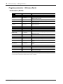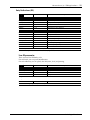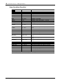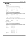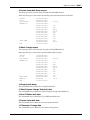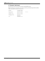
1
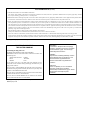
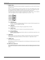
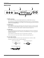
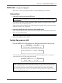
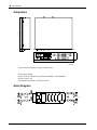
DIGITAL REVERBERATOR
Owner’s Manual
Manuel d’instructions
Bedienungsanleitung
Manual del propietario
DATA/CURSOR
DIGITAL REVERBERATOR
7
8
9
EQ ON
4
5
6
STORE
GATE
GATE ON
1
2
3
CANCEL
UTILITY
LEVEL/
BAL
OTHERS
0
•
–
RECALL/
ENTER
BYPASS
EQ
PRESET
USER
PROGRAM
PROGRAM
INFINITE
POWER
DEC
MIDI
PRE EFFECT EQ
INPUT
0
FREQ
100
GAIN
300
FREQ
800
GAIN
4k
2k
FREQ
10k
GAIN
ON
COMPARE
50
700 -15
+15
350
5k
-15
+15
2k
20k -15
+10
L
FINE
MAIN
STEREO
L
R MONO
CLIP
-3
-6
-9
-12
-18
-24
-36
-00
PARAMETER
INC
R
L
R
LOW
MID
HIGH
+15
ON/ OFF
FCC INFORMATION (U.S.A.)
1. IMPORTANT NOTICE: DO NOT MODIFY THIS UNIT!
This product, when installed as indicated in the instructions contained in this manual, meets FCC requirements. Modifications not expressly approved by Yamaha
may void your authority, granted by the FCC, to use the product.
2. IMPORTANT: When connecting this product to accessories and/or another product use only high quality shielded cables. Cable/s supplied with this product MUST
be used. Follow all installation instructions. Failure to follow instructions could void your FCC authorization to use this product in the USA.
3. NOTE: This product has been tested and found to comply with the requirements listed in FCC Regulations, Part 15 for Class “B” digital devices. Compliance with
these requirements provides a reasonable level of assurance that your use of this product in a residential environment will not result in harmful interference with
other electronic devices. This equipment generates/uses radio frequencies and, if not installed and used according to the instructions found in the users manual, may
cause interference harmful to the operation of other electronic devices. Compliance with FCC regulations does not guarantee that interference will not occur in all
installations. If this product is found to be the source of interference, which can be determined by turning the unit “OFF” and “ON”, please try to eliminate the
problem by using one of the following measures:
Relocate either this product or the device that is being affected by the interference.
Utilize power outlets that are on different branch (circuit breaker or fuse) circuits or install AC line filter/s.
In the case of radio or TV interference, relocate/reorient the antenna. If the antenna lead-in is 300 ohm ribbon lead, change the lead-in to coaxial type cable.
If these corrective measures do not produce satisfactory results, please contact the local retailer authorized to distribute this type of product. If you can not locate the
appropriate retailer, please contact Yamaha Corporation of America, Electronic Service Division, 6600 Orangethorpe Ave, Buena Park, CA 90620
* This applies only to products distributed by YAMAHA CORPORATION OF AMERICA.
IMPORTANT NOTICE FOR
THE UNITED KINGDOM
Connecting the Plug and Cord
WARNING: THIS APPARATUS MUST BE EARTHED
IMPORTANT: The wires in this mains lead are coloured in accordance with
the following code:
GREEN-AND-YELLOW
BLUE
BROWN
: EARTH
: NEUTRAL
: LIVE
As the colours of the wires in the mains lead of this apparatus may not
correspond with the coloured markings identifying the terminals in your
plug, proceed as follows:
The wire which is coloured GREEN and YELLOW must be connected to
the terminal in the plug which is marked by the letter E or by the safety earth
symbol or coloured GREEN and YELLOW.
The wire which is coloured BLUE must be connected to the terminal which
is marked with the letter N or coloured BLACK.
The wire which is coloured BROWN must be connected to the terminal
which is marked with the letter L or coloured RED.
* This applies only to products distributed by YAMAHA KEMBLE
MUSIC (U.K.) LTD.
ADVARSEL!
Lithiumbatteri—Eksplosionsfare ved fejlagtig
håndtering. Udskiftning må kun ske med batteri
af samme fabrikat og type. Levér det brugte
batteri tilbage til leverandoren.
VARNING
Explosionsfara vid felaktigt batteribyte. Använd
samma batterityp eller en ekvivalent typ som
rekommenderas av apparattillverkaren.
Kassera använt batteri enligt fabrikantens
instruktion.
VAROITUS
Paristo voi räjähtää, jos se on virheellisesti
asennettu. Vaihda paristo ainoastaan
laitevalmistajan suosittelemaan tyyppiin. Hävitä
käytetty paristo valmistajan ohjeiden
mukaisesti.
Precautions i
Precautions
Water warning
Do not expose the device to rain, use it near water or in damp or wet conditions, or place containers on it containing liquids which might spill into any openings.
Avoid excessive heat, humidity, dust, and vibration
Keep the unit away from locations where it is likely to be exposed to high temperatures or
humidity – such as near radiators, stoves, in direct sunlight, etc. Avoid locations which are subject to excessive dust accumulation. Extreme vibrations can cause mechanical damage.
Avoid physical shocks
Strong physical shocks can damage the unit. Handle it with care.
Install the unit with plenty of space for ventilation
This unit should be installed in such a way as to maintain a gap of 10cm or more between the
rear of the unit and the wall. This will prevent heat build-up inside the unit and possible fire hazard.
Do not open the unit, or attempt repairs or modifications yourself
This product contains no user-serviceable parts. Prefer all maintenance to qualified Yamaha service personnel. Opening the unit and/or tampering with the internal circuitry will void the warranty.
Make sure the power is off before making or removing connections
Always turn the power OFF prior to connecting or disconnecting cables. This is important to prevent damage to the unit itself as well as other connected equipment.
Handle cables carefully
Always plug and unplug cables – including the AC cord – by gripping the connector, not the
cord.
Clean with a soft dry cloth
Never use solvents such as benzine or thinner to clean the unit. Wipe it clean with a soft, dry
cloth.
Always use the correct power source
Make sure the power source voltage specified on the rear panel matches your local AC mains
supply:
US & Canadian Model: 120V AC, 60 Hz
General Model: 230V AC, 50 Hz
UK Model: 240V AC, 50 Hz
Back-up battery
This unit contains a long-life lithium battery which maintains the contents of user memory locations even when the unit is off. With normal use, the battery should last approximately five
years. If the battery voltage falls below a certain level, the message “WARNING LOW BATTERY” will appear on the screen when the power is turned on. If this occurs, have the battery
replaced at a qualified Yamaha service center.
Warning: DO NOT ATTEMPT TO REPLACE THE BATTERY YOURSELF. OPENING THE UNIT
AND/OR TAMPERING WITH THE INTERNAL CIRCUITRY WILL VOID THE WARRANTY.
ProR3 Digital Reverberator
ii Contents
Contents
Introduction . . . . . . . . . . . . . . . . . . . . . . . . . . . . . . .1
ERROR Messages of the ProR3 . . . . . . . . . . . . 36
Front panel . . . . . . . . . . . . . . . . . . . . . . . . . . . . . . . .2
Specifications . . . . . . . . . . . . . . . . . . . . . . . . . . . . 37
Rear panel. . . . . . . . . . . . . . . . . . . . . . . . . . . . . . . . .6
Dimensions . . . . . . . . . . . . . . . . . . . . . . . . . . . . . . 38
Block Diagram . . . . . . . . . . . . . . . . . . . . . . . . . . . 38
Basic use – using a preset program – . . . . .7
MIDI data format . . . . . . . . . . . . . . . . . . . . . Add-1
Connections . . . . . . . . . . . . . . . . . . . . . . . . . . . . . .7
Turning the power on (off). . . . . . . . . . . . . . . . . .7
Adjusting the input level . . . . . . . . . . . . . . . . . . .8
Selecting effect programs . . . . . . . . . . . . . . . . . . .8
Preset Program List . . . . . . . . . . . . . . . . . . . . . . . .9
Advanced uses (1) . . . . . . . . . . . . . . . . . . . . . . .12
The bypass function . . . . . . . . . . . . . . . . . . . . . .12
Pre-effect EQ. . . . . . . . . . . . . . . . . . . . . . . . . . . . .12
The INFINITE function. . . . . . . . . . . . . . . . . . . .13
Advanced uses (2) – Editing functions – . .14
How programs are organized . . . . . . . . . . . . . .14
Editing procedure . . . . . . . . . . . . . . . . . . . . . . . .15
Program parameters 1 (Primary effects) . . . . .18
Reverberation (Reverb) . . . . . . . . . . . . . . . .18
Early Reflections (ER) . . . . . . . . . . . . . . . . . .19
User ER parameter . . . . . . . . . . . . . . . . .19
Room Simulation (RoomSim) . . . . . . . . . . .20
Reverb + Echo (Rev + Ech) . . . . . . . . . . . . .21
Reverb + Early Reflections (Rev + ER) . . . .22
Reverb + Chorus (Rev + Cho) . . . . . . . . . . .23
Reverb + Symphonic (Rev + Sym) . . . . . . .24
Reverb + Flanger (Rev + Flg) . . . . . . . . . . . .25
Reverb + Pitch Change (Rev + Pit) . . . . . . .26
Reverb + Auto Pan (Rev + PAN) . . . . . . . .27
Common parameters . . . . . . . . . . . . . . . . . .27
Program paramaters 2 (Secondary effects) . . .28
DFL . . . . . . . . . . . . . . . . . . . . . . . . . . . . . . . . .28
COMP . . . . . . . . . . . . . . . . . . . . . . . . . . . . . . .29
EQ . . . . . . . . . . . . . . . . . . . . . . . . . . . . . . . . . .30
GATE . . . . . . . . . . . . . . . . . . . . . . . . . . . . . . .31
LEVEL/BAL . . . . . . . . . . . . . . . . . . . . . . . . .32
Advanced uses (3) – Utility functions – . . .33
Memory protect settings. . . . . . . . . . . . . . . . . . .33
Input mode setting . . . . . . . . . . . . . . . . . . . . . . .33
MIDI channel setting. . . . . . . . . . . . . . . . . . . . . .34
Setting the MIDI program change table . . . . . .34
Transmitting a MIDI bulk dump. . . . . . . . . . . .35
Assigning MIDI controllers . . . . . . . . . . . . . . . .35
Initializing the ProR3 . . . . . . . . . . . . . . . . . . . . .36
ProR3 Digital Reverberator
1. Transmitted data . . . . . . . . . . . . . . . . . . . Add-1
2. Receive data . . . . . . . . . . . . . . . . . . . . . . . Add-5
MIDI Implementation Chart . . . . . . . . . . Add-9
Introduction 1
Introduction
Thank you for purchasing the Yamaha ProR3 Digital Reverberator. The ProR3 marks a new era in
Yamaha’s reverberation technology. Third-generation Yamaha digital signal processors (DSP)
with 32 bit digital signal processing and high-performance 20 bit linear A/D and D/A converters provide unprecedented density and resolution, with breathtakingly dynamic impact. The
ultra-high quality analog input and output circuitry achieves a dynamic range of 110 dB, providing incredibly natural reverberance with a noiseless decay.
The ProR3 has 10 primary effects; reverb, early reflection, room simulation, and combinations of
reverb with echo, chorus, flanging, pitch change, and auto pan, etc. A pre-effect EQ is provided
in front of the primary effect, and following the primary effect, dynamic filter, compressor, EQ,
gate, level, and balance stages are provided. In stereo input mode, full stereo reverb is provided.
In addition to 90 preset programs for immediate use, 90 user memory locations are provided for
your own custom settings.
The stereo inputs and outputs feature both balanced XLR type and 1/4" phone jack connectors,
for connection to a variety of equipment. The input and output level selectors (–10 dB/+4 dB)
also allow flexibility in level adjustment. Programs can be selected from an external MIDI device,
and bulk data dumps can also be performed.
The Yamaha ProR3 digital reverberator is the result of an important step forward in digital reverberation technology. It provides a previously unattainable level of rich reverberation effects,
sound quality, and operability, and is an ideal reverberator for use in any situation, from the
home studio to pro audio recording and PA work.
In order to take full advantage of the ProR3’s functionality and enjoy years of trouble-free use,
please read this manual carefully.
ProR3 Digital Reverberator
2 Front panel
Front panel
2
1
3
4
6
5
DATA/CURSOR
DIGITAL REVERBERATOR
8
9
PARAMETER
FINE
7
8
9
EQ ON
4
5
6
STORE
GATE
GATE ON
1
2
3
CANCEL
UTILITY
LEVEL/
BAL
OTHERS
0
•
–
RECALL/
ENTER
BYPASS
MAIN
PROGRAM
INFINITE
POWER
INC
R
L
7
CLIP
-3
-6
-9
-12
-18
-24
-36
STEREO
L
R MONO
EQ
PRESET
USER
PROGRAM
MIDI
FREQ
GAIN
DEC
PRE EFFECT EQ
INPUT
0
100
FREQ
300
800
GAIN
2k
FREQ
4k
10k
GAIN
COMPARE
50
700 -15
+15
350
5k
-15
+15
2k
20k -15
ON/ OFF
ON
+15
+10
-00
L
R
LOW
MID
HIGH
A
0
1
B
C D
INPUT level meters (L/R)
This is a stereo LED meter with 8 segments for each channel. The segments respectively indicate
levels of –36 dB, –24 dB, –18 dB, –12 dB, –9 dB, –6 dB, –3 dB, and CLIP.
Note: The level meters are located in the circuitry after the A/D converter. This means that the CLIP
indicator will indicate clipping of the digital signal. Adjust the input level so that the CLIP indicator
does not light.
2
PROGRAM number display
This is a two-digit seven-segment display that indicates the currently selected program number.
If this display is blinking, a new program has been selected but its contents have not yet been
recalled.
3
Status indicators
These are six LEDs which indicate program status and other functions of the ProR3.
STEREO, L/R MONO
The input mode of the currently selected program is shown by three indicators. The ProR3 has
four input modes (Stereo, LR/Mix, R-Mono, L-Mono), selected by the UTILITY key. When both
L/R Mono indicators are lit, LR/Mix mode is selected.
PRESET/USER
These indicators show the program status. Use the PROGRAM key to select the status. When the
PRESET indicator is lit, preset programs are selected. When the USER indicator is lit, user programs are selected.
MIDI
This indicator will light while MIDI data is being received from an external device connected to
the MIDI IN connector.
4
LCD
This backlit LCD shows the name of the selected program and the program parameter values.
Messages related to operation will also appear here.
ProR3 Digital Reverberator
Front panel 3
5
DATA/CURSOR keys
The DATA keys (INC) (DEC) are used to modify the value of the selected parameter.
The CURSOR keys (√) (®) are used to select parameters displayed in the LCD.
When the PROGRAM indicator is lit, the DATA keys are used to select the program that you
wish to recall.
6
PARAMETER keys
These keys select effect parameters. Each time a key is pressed, it will cycle through the parameter pages, and will finally return to the first page.
MAIN
FINE
A
B
EQ
EQ ON
C
GATE
GATE ON
LEVEL/
BAL
OTHERS
D
F
E
6-A MAIN key
This key accesses the main parameters. The indicator will light, and you will be able to
edit the main parameters of the program.
6-B
FINE key
This key accesses secondary parameters of the program. The indicator will light, and you
will be able to edit the secondary parameters of the program.
6-C EQ, EQ ON keys
The EQ key accesses the parameters of the three-band post-effect equalizer. The indicator
will light, and you will be able to edit the EQ type, frequency, gain, and Q for each band.
The EQ ON key turns the post-effect equalizer on/off. When the equalizer is on, the green
indicator will light.
LOW
MID
HIGH
Type
Peaking/Shelving
Peaking
Peaking/Shelving
Gain
±15 dB
±15 dB
±15 dB
32 Hz to 2.2 kHz
250 Hz to 5.6 kHz
500 Hz to 20 kHz
0.1 to 5.0
0.1 to 5.0
0.1 to 5.0
Frequency
Q
6-D GATE, GATE ON keys
The GATE key accesses the gate parameters. The indicator will light, and you will be able
to edit the level and balance, etc.
The GATE ON key turns the gate on/off. When the gate is on, the green indicator will
light.
6-E
LEVEL/BAL key
This key lets you adjust the effect balance (the level balance between the direct sound and
the effect sound). When you press the key, the red indicator will light.
6-F
OTHERS key
This key has two functions. When you press the key, the red indicator will light.
1 Specify a program title (see page 16).
2 Select the parameters to be controlled by MIDI Control Change messages (see page 16
and 35).
ProR3 Digital Reverberator
4 Front panel
7
Numeric keys
These keys are used to directly input the number of a program that you wish to recall, or to input
parameter values.
When you use the numeric keys to input a parameter value, the value will blink until it is finalized. Press the RECALL/ENTER key to finalize the value. To return to the original value, press
the CANCEL key. Some parameters cannot be entered using the numeric keys.
To specify a negative value (for example an equalizer gain of –9 dB), use the “–” key. To specify a
value with a decimal point (for example an equalizer Q of 2.5), use the “.” key.
7
8
9
4
5
6
STORE
1
2
3
CANCEL
0
•
–
RECALL/
ENTER
PROGRAM
A
B
C
D
7-A PROGRAM key
This key is used when selecting programs. Each time you press the key, the program status
will alternate between PRESET and USER.
7-B
STORE key
This key is used to store the settings of a program that you created.
7-C CANCEL key
This key is used to cancel a value that was entered by the numeric keys.
7-D RECALL/ENTER key
This key is used to recall a program whose number was entered by the numeric keys, or to
finalize a parameter value.
8
INFINITE key
When this key is pressed, the indicator will light, and the RevTime parameter will be dramatically lengthened. This produces the effect of a “freeze-frame” or “stop-motion” sound.
9
POWER switch
This switch turns the power on/off.
When the power is turned on, the program that was last being used when the power was turned
off will be selected.
10 INPUT level control (L, R)
The inner knob is the input level for the left channel, and the outer knob is the input level for the
right channel. The knobs are coaxial for convenience when you are adjusting the level of a stereo
source.
ProR3 Digital Reverberator
Front panel 5
11 PRE EFFECT EQ, ON controls
This is a three-band parametric equalizer that equalizes the signal before the effect. The center
frequency and gain can be set for each band.
The ON key turns the pre-effect equalizer on/off. When the equalizer is on, the green indicator
will light.
Frequency
Gain
LOW
MID
HIGH
50 Hz to 700 Hz
350 Hz to 5 kHz
2 kHz to 20 kHz
±15 dB
±15 dB
±15 dB
12 COMPARE key
After editing the parameters of a program, you can use this key to compare the edited sound
with the sound of the program at the time it was recalled. When the red indicator is lit, you are
hearing the original sound of the program.
13 UTILITY key
Use this key when you wish to make settings for system parameters such as memory protect,
input mode, and MIDI parameters. When you press the key, the red indicator will light.
14 BYPASS key
When this key is pressed, the input signal will be output directly without passing through the
effect, and the red indicator will light.
This is a convenient way to quickly compare the unprocessed sound with the processed sound.
ProR3 Digital Reverberator
6 Rear panel
Rear panel
E
F
MIDI
OUTPUT
G
INPUT
R
THRU
OUT
L
R
L
IN
R
L
R
–10dB +4dB
L
–10dB +4dB
H
15 MIDI connectors
These are 5 pin DIN type standard MIDI IN, MIDI OUT, and MIDI THRU connectors.
These connectors are used when transmitting program change messages or control change messages from an external MIDI device to the ProR3, or when transmitting program bulk dump data
from the ProR3 to another device.
16 OUTPUT jacks
These are balanced output jacks which output the analog return signal to your mixer or multitrack recorder, etc. A pair of XLR-3-32 connectors and a pair of 1/4" phone jacks are provided.
The level select switch selects either +4 dB or –10 dB as the nominal output level.
17 INPUT jacks
These are balanced input jacks which input the analog signal from your mixer or multi-track
recorder to the ProR3. If the source is monaural, use the UTILITY key to select an appropriate
input jack (see page 33).
A pair of XLR-3-31 connectors and a pair of 1/4" phone jacks are provided.
The level select switch selects either +4 dB or –10 dB as the nominal input level.
18 Level select switches
These switches change the level of the input/output jacks between +4 dB and –10 dB.
Set them to match the level of the connected equipment.
XLR3-31 type pin arrangement
Hot
2
1
Ground
(Earth)
3
Cold
1/4" phone plug signal connections
Ground
Cold
ProR3 Digital Reverberator
Hot
XLR3-32 type pin arrangement
Ground
(Earth)
1
2
3
Hot
Cold
Basic use – using a preset program – 7
Basic use – using a preset program –
Here’s how to select a preset program and use it without adjusting any parameters.
Connections
1. Connect the sound source to the INPUT jacks.
Warning: Before making connections, make sure that the power is turned off for all
your equipment.
For a stereo sound source, connect the outputs of both channels to the INPUT jacks. For a monaural sound source, use the L input jack.
If the sound source has XLR connectors, make connections using the XLR-3-31 connectors of the
ProR3. If not, use the 1/4" phone jacks.
2. Connect the OUTPUT jacks to the mixer or other external device.
If the mixer has XLR connectors, make connections using the XLR-3-32 connectors of the ProR3.
If not, use the 1/4" phone jacks.
Note: You may also use a cable which converts between XLR connectors and TRS 1/4" phone jacks.
3. Connect the ProR3 to an AC outlet.
Turning the power on (off)
1. Press the POWER switch to turn the power on. (Pressing it again will turn the power off.)
YAMAHA
ProR3
Digital Reverberator
Copyright(c) 1995 YAMAHA
The initial display will appear for a few seconds, and then the program that was being used
when the power was last turned off will be selected.
Large Hall 1
RevTime =
Reverb
2.5s
Note: When turning on the equipment in a system, always turn on each device in sequence of the signal flow, starting from signal sources and ending with the power amp. Observing this sequence will
prevent damage to speakers, to other equipment, or to your hearing which can be caused by the noise
that occurs when a device is turned on. Turn on the ProR3 before the other connected equipment.
When turning off the power of the system, turn off devices starting with the power amp and working
backward toward the signal sources.
ProR3 Digital Reverberator
8 Basic use – using a preset program –
Adjusting the input level
When the power has been turned on for the ProR3 and the other equipment, make the sound
sources produce sound, and adjust the input level of the ProR3.
1. Rotate the INPUT level controls while watching the INPUT level meters.
Set the levels to achieve maximum S/N ratio while not allowing the CLIP indicators to light.
Selecting effect programs
There are two ways to select programs.
• Use the INC/DEC keys.
Press the INC or DEC key to select a program.
If you hold down a key, the program numbers will change in succession.
• Use the numeric keys and the RECALL/ENTER key.
1 Use the numeric keys to select the program number, and the PROGRAM indicator will
blink.
If you enter the wrong number, press the CANCEL key, and use the numeric keys to enter
the number once again.
If you select a number other than 1–90, the display will indicate “ NO PROGRAM No Type”. Press the CANCEL key to return to the previous display.
**
**
2 Press the RECALL/ENTER key to recall the program.
When the program is recalled, the PROGRAM indicator will change from blinking to lit.
If you select a number other than 1–90 and press the RECALL/ENTER key, the display
will indicate “ Program Number Error ”. Press the CANCEL key to return to the previous display.
*
*
Note: If the display asks “Recall? Are you sure?” when you select a program, this indicates that the
data of the program has been edited. If you wish to save this edited data, use the procedure “Saving a
program” given on page 16.
If you do not need to save the edited data, press the RECALL/ENTER key to recall the selected program.
ProR3 Digital Reverberator
Basic use – using a preset program – 9
Preset Program List
No.
Title
Type
Description
Large Hall
1
Large Hall 1
Reverb
2
Large Hall 2
Reverb
3
New Hall
Reverb
A program with a slight delay between the sparse early reflections and the rich
reverberation.
4
Wide Hall
Reverb
A program simulating a spacious and uncolored hall.
5
Breathless Hall
Reverb
A bit of character. Bright, strong, and somewhat long reverb.
The ProR3’s standard hall-type reverb. Simulates a large hall with good acoustics, and is suitable for any instrument.
Medium Hall
6
Medium Hall 1
Reverb
7
Medium Hall 2
Reverb
8
Wonder Hall
Reverb
9
Gothic Hall
Rev+Cho
10
Bright Ham
Reverb
A bright medium sized hall.
A standard medium-sized hall reverb.
Reverb with a lighter feel than the large hall type. Try it with percussion.
A combination of chorus and a somewhat long reverb. Try it on solo instruments,
vocals, or pads.
Small Hall
11
Small Hall 1
Reverb
An idealized small hall with a small stage.
12
Small Hall 2
Reverb
An even smaller hall. The internal compressor is on, producing a damped reverb
sound.
13
Small Dark Hall
Rev+ER
Small hall, somewhat darker in tone. Try it on vocals in a minor key.
14
Pool
Reverb
Small hall program with many early reflections.
15
Open Hall
Reverb
Small hall with open space. For vocals.
Large Room
16
Large Room 1
Reverb
Simulation of a large room with hard walls. A thick and somewhat idiosyncratic
sound. Try it on percussion.
17
Large Room 2
Reverb
Compared to Large Room 1, a room with more naturalness and transparency.
18
Mood Room
Reverb
Large room with slightly darker tone.
19
Soft Room
Reverb
Large room with mellow tone.
20
Attack Room
Rev+Pit
Combines a pitch change (±9 cents) with a room. Creates depth for vocals or solo
instruments.
Medium Room
21
Medium Room 1
Reverb
Simulates a medium sized studio with good acoustics. Apply to a 2-channel
source for “live in the studio.”
22
Medium Room 2
Reverb
Simulates a somewhat live recording studio with wood walls.
23
Dark Room
Reverb
A studio slightly smaller than Medium Room 2, with a natural acoustics.
24
Quick Room
Reverb
A dry-sounding studio with wood and metal walls. For brass or percussion.
25
Aquarium
RoomSim
26
Wood Room
RoomSim
27
Chorus Room
Rev+Cho
28
Delayed Room
RoomSim
An echo room with an 82 ms pre-delay. For sax or solo instruments.
29
Comp. Chamber
RoomSim
A room program for snare or percussion. Use Threshold to adjust the degree of
compression.
Simulates the reverberation of a medium-sized studio. Try on bass drum.
Adds the airiness of a medium room to thicken the sound.
Small Room
30
Small Room 1
RoomSim
31
Small Room 2
Rev+Cho
32
Small Studio
RoomSim
33
Bright Studio
Reverb
34
Kick Chamber
RoomSim
35
Tiny Room
36
Near You
The small room programs are extremely short reverbs created with hip-hop in
mind. These are meant to be applied in small amounts, so that the sound appears
either dry or to have the natural acoustics of a studio. They are especially effective on sequenced instruments, synth brass, and on instruments recorded in a
dead studio.
ER
Rev+Pit
ProR3 Digital Reverberator
10 Basic use – using a preset program –
No.
Title
Type
Description
Special Room
37
Power Drum Room
RoomSim
Adds a strong live ambiance to drums. Try it on sampled drums.
38
Soft Space
Rev+Cho
A percussive short reverb with chorus added. Gives ambiance to drums, lead
instruments, and vocals.
39
Droid Short
Reverb
40
Droid Long
Reverb
41
Tile Room
RoomSim
42
Coliseum
Reverb
Long reverb of a wide space, simulating a coliseum.
43
Opera
Reverb
Fairly long reverb with a 52 ms delay between the early reflections and the reverb.
44
Delay Hall
Ech→Rev
Reverb
Simulates an early and extremely expensive digital reverb unit.
The bright ambiance of a tiled room.
A combination of hall-type reverb and delay. Set the L and R Delay and IniDly
parameters to match the tempo of the song.
45
Train Station
46
Tile Bathroom
ER
Try this when you need echoing footsteps in a late-night train station.
47
Closet
ER
48
Motel Chorus
ER
49
Pitch Room
Pit→Rev
Reverb applied to a pitch change (±8 cents). For vocals or chorus.
50
Beauty Plate
Reverb
Sub-reverb settings have been boosted. Try it on an electric piano.
51
Arena Plate
Reverb
Simulates a gigantic arena like the Budokan in Tokyo.
These programs provide early reflections alone. Try them when you wish to add
room ambiance to drums, percussion, guitar, line-recorded bass, electric piano,
and solo instruments.
Plate
52
Vocal Plate 1
Reverb
Try it on vocals. Especially nice for ballads.
53
Vocal Plate 2
Reverb
Reverb with a darker feel than Vocal Plate 1.
54
Vocalese
55
String Plate
Rev+Cho
Reverb
Chorus is lightly applied to the reverb. Try it on guitar and keyboards.
Try it on strings for an even more beautiful sound.
56
Home Plate
Reverb
Metal plate reverb from the good old days.
Simulations of the bright and crisp plate reverb preferred in studios on the US
west coast.
57
LA Plate Short
Reverb
58
LA Plate Long
Reverb
59
Short Perc.Plate
Reverb
Short and bright percussion plate. Set the IniDelay parameter according to the
tempo.
60
Long Plate
Reverb
Longer plate reverb. Try it on organ pads etc.
61
ER Gate 1
ER
62
ER Gate 2
ER
63
ER for Kick
ER
64
Power Gate 1
ER
65
Power Gate 2
ER
66
Room Gate
ER
67
Gated Rev 1
Reverb
68
Gated Rev 2
Reverb
69
Reverse Gate 1
ER
70
Reverse Gate 2
ER
Gate
These are gated reverbs with only the early reflections.
ER Gate 1 is a natural and uncolored gate. ER Gate 2 is a bit metallic. ER for Kick
is for when you want to fatten up a thin sounding bass drum.
Adjust the Liveness and RoomSize parameters as desired.
As the names suggest, Power Gate 1 and Power Gate 2 are for when you want to
make the drums really stand out.
These are standard combinations of reverb + noise gate. Compared to the gated
programs consisting only of E.Ref, more detailed settings are required to fit them
to your song, but this also means that you have more control.
These simulate the gated reverb effect produced by a tape running backwards,
like the Reverse Gate programs on the REV7 and REV5. Make settings to match
the tempo of the song.
Effect Reverb
71
Reverb Flange 1
Reverb
72
Reverb Flange 2
Rev→Flg
73
Reverb Flange 3
Rev→Flg
74
Reverb Flange 4
Rev→Flg
75
Dark Moon
Rev→Flg
76
Filter Flange
Rev→Flg
ProR3 Digital Reverberator
Reverb Flange 1 is natural. Reverb Flange 2 through Reverb Flange 4 sound progressively deeper and more showy.
Basic use – using a preset program – 11
No.
Title
Type
Reverb
Description
77
Super Long Decay
78
Slow Pan Reverb
Rev→Pan
A fairly long reverb is panned slowly.
79
Sub Aqua
Pit→Rev
Water sounds producing a “sprong” when applied to a rim shot. When applied to
strings, a saw-like sound results.
80
Thud
Pit→Rev
81
Alien Attack
Pit→Rev
82
High Filter
Reverb
83
High Mid Filter
Reverb
84
Low Mid Filter
Reverb
85
Low Filter
Reverb
86
Chorus Reverb
Rev+Cho
87
Symphonic Rev 1
Rev+Sym
88
Symphonic Rev 2
Sym→Rev
89
Echo Reverb 1
Ech→Rev
90
Echo Reverb 2
Ech→Rev
An effect like an extremely long tunnel.
Turns an acoustic instrument into a synth! Produces an auto-wah like effect when
applied to guitar.
Effect reverb with a sense of definite pitch created by the dynamic filter. Try it on
rim shots, or percussive instruments and sound effects.
This program combines a chorus effect and reverb to create spaciousness and
depth.
A multi-phase chorus combined symphonic effect and reverb creates spaciousness and depth, with a multi-phase chorus.
Reverb is applied to a stereo feedback echo of up to 400 ms left and right.
ProR3 Digital Reverberator
12 Advanced uses (1)
Advanced uses (1)
The bypass function
When you press the BYPASS key, the circuit will be switched so that the input sound is output
directly. This function provides an easy way to make a quick comparison between the sound processed by the effect program and the unprocessed sound. When the effect is bypassed, the red
indicator will light.
PRE
EFFECT
EQ
BYPASS
EFFECT
ON
Pre-effect EQ
The PRE EFFECT EQ controls allow you to make settings for the three-band pre-effect equalizer.
For each band, you can set the center frequency and the gain.
Frequency
Gain
LOW
MID
HIGH
50 Hz to 700 Hz
350 Hz to 5 kHz
2 kHz to 20 kHz
±15 dB
±15 dB
±15 dB
1. Press the PRE EFFECT EQ ON key to turn on the equalizer.
The green indicator will light.
2. Select a band, and rotate its control knobs to adjust the gain.
3. Rotate the FREQ (frequency) control of the selected band.
To hear the effect of the equalizer, first adjust the gain level of the selected band, and then adjust
the frequency.
The equalizer control settings are not stored in the program memory. If the equalizer is turned
on, its settings will affect all programs.
Note: The pre-effect equalizer controls are located in the circuit after the INPUT level meters. This
means that you need to be careful when setting gain levels, since even if the gain is raised excessively
and digital clipping occurs, this will not be indicated by the meters.
ProR3 Digital Reverberator
Advanced uses (1) 13
The INFINITE function
The INFINITE function lets you set an extremely long reverb time. This is effective when used on
the ending of a song, etc.
The INFINITE key can be used in the following two ways.
• Press and immediately release the INFINITE key.
The reverb time will be set to the maximum. Press the key once again and the reverb time will
return to the original value.
• Press hold the INFINITE key.
The reverb time will be set to the maximum as long as you continue holding the key. When
you release the key, the reverb time will return to the original value.
Note: For programs whose primary effect is early reflection (ER) and do not have a RevTime parameter, therefore this key will have no effect.
ProR3 Digital Reverberator
14 Advanced uses (2) – Editing functions –
Advanced uses (2) – Editing functions –
Preset programs are “ready-made” programs. In contrast, user programs can be tailor-made to
meet your needs. This section explains how you can edit your own programs.
How programs are organized
Each of the ProR3 program consists of two main stages; the primary effect and the secondary
effects.
Of these, the primary effect can be selected from one of the following ten types, and will depend
on the program that you select.
Single type:
Compound type:
Reverb, ER, Room Sim
Rev+Ech, Rev+ER, Rev+Cho, Rev+Sym, Rev+Flg, Rev+Pit, Rev+PAN
The “+” in compound type effects such as “Rev+Ech” means that these
effects simultaneously apply both reverb (Rev) and echo (Ech). You can
select the order in which these occur; i.e., whether reverb will be
applied and then echo, or echo applied and then reverb.
The secondary effects are supplementary, and are the following five which are provided for each
program: DFL (dynamic filter), COMP (compressor), EQ, GATE, and LEVEL/BAL.
The primary effect is the decisive factor in determining the character of the entire effect, and if
you know its type, you will have a good idea of how the entire program will sound. For this reason, when the program is shown in the LCD, the primary effect type used by that program will
be shown along with the program number and title, and is also given in the list.
Program title
Program number
Primary effect type
Large Hall 1
RevTime =
Parameter
Reverb
2.5s
Parameter value
The ProR3 has separate dedicated keys for recalling the parameters of the primary effect and the
secondary effects.
Secondary effects
Primary effect
Reverb
ER
Room Sim
Rev+Ech
Rev+ER
Rev+Cho
Rev+Sym
Rev+Flg
Rev+Pit
Rev+PAN
MAIN
ProR3 Digital Reverberator
DFL
FINE
COMP
EQ
EQ
GATE
EQ
ON
GATE
GATE
ON
LEVEL/
BAL
LEVEL/
BAL
Advanced uses (2) – Editing functions – 15
Editing procedure
1) Selecting a program
Refer to the list of preset programs on page 9 or the included preset program list, and select the
number of the program that you wish to edit.
At this time, it is not possible to change the type of the primary effect, so make your choice of
type carefully.
Primary effect type
Large Hall 1
RevTime =
Reverb
2.5s
2) Editing parameters
1. Press the key which accesses the program parameter that you wish to edit. For example
to edit primary effect parameters, press the MAIN key or FINE key. To edit GATE parameters, press the GATE key.
Pages 18 and following have lists of the parameters which are accessed by each key.
2. Repeatedly press the key until the parameter that you wish to edit appears.
3. Use the cursor keys (√) (®) to move the cursor to the parameter that you wish to edit.
4. There are two ways to set the value of a parameter.
• Press the INC or DEC key to set the value.
If you continue holding down a key, the value will continue to change.
• Use the numeric keys and the RECALL/ENTER key to set the value.
1 Use the numeric keys to enter the value, and the data will blink. If you make a mistake,
press the CANCEL key, and input the value once again using the numeric keys.
2 Press the RECALL/ENTER key to finalize the setting.
5. By pressing the COMPARE key, you can compare the sound after the parameter was
edited with the sound that the program had when it was recalled.
6. If you wish to edit the parameter again, return to step 3.
7. If you wish to edit a different parameter in the same effect, return to step 2.
8. If you wish to edit a different effect, refer to step 1.
ProR3 Digital Reverberator
16 Advanced uses (2) – Editing functions –
3) Entering a title
You can enter a program name of up to 16 characters for each of your own effect programs.
1. Press the OTHERS key.
The red indicator will light. Each time you press the OTHERS key, the title edit page and two
controller parameter pages will alternate.
Title Edit
[Dread Lurgi Verb]
2. Use the CURSOR keys (√) (®) to select the location of the character.
The cursor will indicate the location when a character can be selected. Each time you press the
CURSOR key, the cursor will move to the next/previous character location, and will “wrap
around” when it reaches the end of the title.
3. Press the INC or DEC key to change the character. You can also use the numeric keys to
enter numerals.
If you continue holding the INC or DEC key, the character will continue to change. The numerals
0 through 9, a “–” (minus), and a “.” (decimal point) can be entered using the numeric keys.
4) Setting MIDI control parameters
You can specify parameters to be controlled via MIDI, and the range of control. (refer page 35)
1. Press the OTHERS key to access the MIDI control page.
Ctr1-1 Prm
RevTIM
Min
Max
0.0% 100.0
2. Use the CURSOR keys (√) (®) to select parameters.
3. Use the INC and DEC keys to set the parameters.
Control 1 Prm
–
Select the parameter controlled by MIDI controller 1
Control 1 Min
0.0–100.0%
Minimum value of the range of MIDI controller 1
Control 1 Max
0.0–100.0%
Maximum value of the range of MIDI controller 1
Control 2 Prm
–
Select the parameter controlled by MIDI controller 2
Control 2 Min
0.0–100.0%
Minimum value of the range of MIDI controller 2
Control 2 Max
0.0–100.0%
Maximum value of the range of MIDI controller 2
5) Saving a program
Up to 90 programs whose parameters you have edited can be saved as USER programs.
1. Press the STORE key.
The PROGRAM indicator will blink, and a message will appear to ask the storing location.
Circus Big Top
Reverb
Store from P01 to U01 ?
ProR3 Digital Reverberator
Advanced uses (2) – Editing functions – 17
If the USER program area is protected (i.e., if Memory Protect is ON), a message of “MEMORY
PROTECTED” will appear.
If this occurs, turn off the Memory Protect utility function as explained on page 33 before storing
your program.
2. The upper line of the display will show the title of the program that already occupies the
storing destination.
Use the INC/DEC keys or the numeric keys to select the storing destination.
Vocal Plate 2
Reverb
Store from P01 to U40 ?
If you use the numeric keys to enter a number outside of the range of 1–90, a message of “ NO
PROGRAM No Type” will appear. Press the CANCEL key to return to the previous display.
**
**
3. To store the program, press the STORE key. To cancel, press the CANCEL key.
Low Mid Filter
Reverb
This Program is Stored
A message of “This Program is Stored” will appear briefly, and then the previous display will
reappear.
If a number outside of the range of 1–90 has been entered using the numeric keys, a message of
“ Store Number Error ” will appear. Press the CANCEL key to return to the previous display.
**
**
ProR3 Digital Reverberator
18 Advanced uses (2) – Editing functions –
Program parameters 1 (Primary effects)
Reverberation (Reverb)
Key
Parameter
Value
Description
MAIN
RevTime
0.3 ~ 99.0 s
Reverb time of primary reverberation (the time required for
60 dB of decay at 1 kHz)
IniDelay
0.1 ~ 200.0 ms
Delay time until the primary reverb begins
HighRatio
X0.1 ~ X1.0
Reverb time of the high frequency components of the reverb;
relative to RevTime
LowRatio
X0.1 ~ X2.4
Reverb time of the low frequency components of the reverb;
relative to RevTime
Diffusion
0 ~ 10
Spread of the reverb sound
Reverb Type
*1
Type of reverb tone
ER/REV Balance
0/100 ~ 100/0
Level balance between early reflections and reverb
ER/REV Delay
0.1 ~ 100.0 ms
Time difference between beginning of early reflections and
beginning of reverb
Liveness
0 ~ 10
Decay characteristics of early reflections; 0:dead, 10:live
Density
0 ~ 100
Density of the early reflections
HPF
Thru, 40 Hz ~ 1.0 kHz
Cutoff frequency of the high pass filter
LPF
400 Hz ~ 20 kHz, Thru
Cutoff frequency of the low pass filter
Rev2 Time
X0.1 ~ X10.0
Decay time of the secondary reverb; relative to primary
reverb
Rev2 Delay *2
0.0 ~ 100.0 ms
Time difference between primary reverb and secondary
reverb
Rev2 Level *2
0 ~ 100%
Level of secondary reverb; relative to primary reverb
Mod Freq
0.05 ~ 40.00 Hz
Frequency of reverb modulation
Mod Depth
0 ~ 100%
Depth of reverb modulation
Mod Delay
0.1 ~ 30 ms
Shorter values produce modulation in the high range, longer
values in the low range.
FINE
Common parameters
Refer to “Common parameters” on page 27
*1 Small Hall, Large Hall, Vocal plate, Perc.Plate, Spring, Echo Room, Strings, Snare, Reverb Flange
*2 Only when the input mode is either L-Mono, R -Mono, or LR-Mix.
ProR3 Digital Reverberator
Advanced uses (2) – Editing functions – 19
Early Reflections (ER)
Key
Parameter
Value
Description
MAIN
ER Type
*1
Type of early reflection simulation
IniDelay
0.1 ~ 200.0 ms
Delay time until early reflections are heard
Liveness
0 ~ 10
Decay characteristics of the early reflections; 0: dead, 10: live
RoomSize
0.1 ~ 25.0
Spacing of reflections
Diffusion
0 ~ 10
Spread of the early reflections
ER Number
1 ~ 40
Number of early reflections
FeedBack Delay
0.1 ~ 1000.0 ms
Delay time of feedback
FeedBack Gain
–99 ~ +99%
Amount of feedback; “-” inverts the phase
FeedBack High
0.1 ~ 1.0
Amount of high range feedback; relative to FeedBack Gain
Density
0 ~ 100
Density of reflections
HPF
Thru, 40 Hz ~ 1.0 kHz
Cutoff frequency of high pass filter
LPF
400 Hz ~ 20 kHz, Thru
Cutoff frequency of low pass filter
0 ~ 10
Modulation level
FINE
Space Mod
Common parameters
Refer to “Common parameters” on page 27
*1 Small Hall, Large Hall, Random, Reverse, Plate, Spring, User A, User B, User C, User D
User ER parameter
There are four User ER banks; A–D.
For each bank, you can specify 40 reflections.
For each reflection, you can specify the delay time, level, and panning.
Key
Parameter
Value
Description
FINE
A-01 Delay
0.1 ~ 1000.0 ms
Delay time of first reflection of bank A
A-01 Level
–100 ~ +100%
Level of first reflection of bank A
A-01 Pan
L16 ~ R16
Pan position of first reflection of bank A
•
•
•
D-40 Pan
Return to the beginning of FINE (ER Number)
ProR3 Digital Reverberator
20 Advanced uses (2) – Editing functions –
Room Simulation (RoomSim)
Key
Parameter
Value
Description
MAIN
RevTime
0.3 ~ 99.0 s
Decay time of reverb
IniDelay
0.1 ~ 200.0 ms
Delay time until reverb is heard
Width
0.5 ~ 46.7 m
Simulation of room width
Height
0.5 ~ 46.7 m
Simulation of ceiling height
Depth
0.5 ~ 46.7 m
Simulation of room depth
Wall Vary
0 ~ 30
Simulation of wall roughness (flat 0 → rough 30)
Wall Vary Fine
–100 ~ +100
Fine adjustment of wall simulation
Listening Position
Front, Center, Rear
Seating position in the room
HighRatio
X0.1 ~ X1.0
Decay time of high range reverb components; relative to RevTime
LowRatio
X0.1 ~ X2.4
Decay time of low range reverb components; relative to RevTime
Diffusion
0 ~ 10
Spread of the reverb sound
Width Fine
–100 ~ +100
Fine adjustment of width simulation
Height Fine
–100 ~ +100
Fine adjustment of height simulation
Depth Fine
–100 ~ +100
Fine adjustment of depth simulation
Width Decay
RT X0.1 ~ 10.0
Decay time of width component of reverb; relative to RevTime
Height Decay
RT X0.1 ~ 10.0
Decay time of height component of reverb; relative to RevTime
Depth Decay
RT X0.1 ~ 10.0
Decay time of depth component of reverb; relative to RevTime
ER/REV Balance
0/100 ~ 100/0
Level balance of early reflections and reverb
ER/REV Delay
0.1 ~ 100.0 ms
Time difference between early reflections and reverb
Density
0 ~ 100
Density of reflections
HPF
Thru, 40 Hz ~ 1.0 kHz
Cutoff frequency of high pass filter
LPF
400 Hz ~ 20 kHz, Thru
Cutoff frequency of low pass filter
0 ~ 10
Modulation level
FINE
Space Mod
Common parameters
ProR3 Digital Reverberator
Refer to “Common parameters” on page 27
Advanced uses (2) – Editing functions – 21
Reverb + Echo (Rev + Ech)
Key
Parameter
Value
Description
MAIN
REV RevTime
0.3 ~ 99.0 s
REV IniDelay
0.1 ~ 200.0 ms
REV HighRatio
X0.1 ~ X1.0
REV LowRatio
X0.1 ~ X2.4
REV Diffusion
0 ~ 10
Refer to “Reverberation” items on page 18
ECHO Lch Delay
0.1 ~ 400.0 ms
Left channel delay time
ECHO Rch Delay
0.1 ~ 400.0 ms
Right channel delay time
ECHO Lch FeedBack
–99 ~ +99%
Left channel feedback amount
ECHO Rch FeedBack
–99 ~ +99%
Right channel feedback amount
ECHO High Ratio
0.1 ~ 1.0
High range feedback amount
ECHO/REV Balance *1
0/100 ~ 100/0
Level balance of echo and reverb
REV Rev Mix *2
0 ~ 100%
Reverb amount
REV Reverb Type
*3
Type of reverb tone
REV Density
0 ~ 100
Density of reverb
REV HPF
Thru, 40 Hz ~ 1.0 kHz
Cutoff frequency of reverb high pass filter
REV LPF
400 Hz ~ 20 kHz, Thru
Cutoff frequency of reverb low pass filter
FINE
REV Space Mod
0 ~ 10
Modulation level of reverb
ECHO Lch IniDelay
0.1 ~ 400.0 ms
Time until the L channel echo appears
ECHO Rch IniDelay
0.1 ~ 400.0 ms
Time until the R channel echo appears
REV Patch
*4
Connection of reverb and echo
Common parameters
*1
*2
*3
*4
Refer to “Common parameters” on page 27
Only when REV Patch is parallel (Reverb + Echo)
Only when REV Patch is serial (Reverb → Echo, Echo → Reverb)
Hall, Room, Vocal, Plate
Reverb + Echo, Echo → Reverb, Reverb → Echo
ProR3 Digital Reverberator
22 Advanced uses (2) – Editing functions –
Reverb + Early Reflections (Rev + ER)
Key
Parameter
Value
Description
MAIN
REV RevTime
0.3 ~ 99.0 s
REV IniDelay
0.1 ~ 200.0 ms
REV HighRatio
X0.1 ~ X1.0
REV LowRatio
X0.1 ~ X2.4
REV Diffusion
0 ~ 10
ER Type
*1
ER IniDelay
0.1 ~ 100.0 ms
ER Liveness
0 ~ 10
ER RoomSize
0.1 ~ 25.0
ER Diffusion
0 ~ 10
Refer to “Reverberation” items on page 18
Refer to “Early reflection” items on page 19
FINE
ER/REV Balance *2
0/100 ~ 100/0
Level balance of ER and reverb
REV Rev Mix *3
0 ~ 100%
Reverb amount
REV Reverb Type
*4
Type of reverb tone
REV Density
0 ~ 100
Density of reverb
REV HPF
Thru, 40 Hz ~ 1.0 kHz
Cutoff frequency of reverb high pass filter
REV LPF
400 Hz ~ 20 kHz, Thru
Cutoff frequency of reverb low pass filter
REV Space Mod
0 ~ 10
Modulation level of reverb
ER Number
1 ~ 14
Number of early reflections
ER Density
0 ~ 100
Density of early reflections
ER HPF
Thru, 40 Hz ~ 1.0 kHz
Cutoff frequency of ER high pass filter
ER LPF
400 Hz ~ 20 kHz, Thru
Cutoff frequency of ER low pass filter
REV Patch
*5
Connection of reverb and ER
Common parameters
*1
*2
*3
*4
*5
Refer to “Common parameters” on page 27
Small Hall, Large Hall, Random, Reverse, Plate, Strings
Only when REV Patch is parallel (Reverb + ER)
Only when REV Patch is serial (Reverb → ER, ER → Reverb)
Hall, Room, Vocal, Plate
Reverb + E.Ref., E.Ref. → Reverb, Reverb → E.Ref.
ProR3 Digital Reverberator
Advanced uses (2) – Editing functions – 23
Reverb + Chorus (Rev + Cho)
Key
Parameter
Value
Description
MAIN
REV RevTime
0.3 ~ 99.0 s
REV IniDelay
0.1 ~ 200.0 ms
REV HighRatio
X0.1 ~ X1.0
REV LowRatio
X0.1 ~ X2.4
REV Diffusion
0 ~ 10
Refer to “Reverberation” items on page 18
CHO Mod Freq
0.05 ~ 40.00 Hz
Chorus modulation frequency
CHO DM Depth
0 ~ 100%
Chorus delay time modulation depth
CHO AM Depth
0 ~ 100%
Chorus amplitude modulation depth
CHO/REV Balance *1
0/100 ~ 100/0
Level balance of chorus and reverb
REV Rev Mix *2
0 ~ 100%
Reverb amount
FINE
REV Reverb Type
*3
Type of reverb tone
REV Density
0 ~ 100
Density of reverb
REV HPF
Thru, 40 Hz ~ 1.0 kHz
Cutoff frequency of reverb high pass filter
REV LPF
400 Hz ~ 20 kHz, Thru
Cutoff frequency of reverb low pass filter
REV Space Mod
0 ~ 10
Modulation level of reverb
REV Patch
*4
Connection of reverb and ER
Common parameters
*1
*2
*3
*4
Refer to “Common parameters” on page 27
Only when REV Patch is parallel (Reverb + Chorus)
Only when REV Patch is serial (Reverb → Chorus, Chorus → Reverb)
Hall, Room, Vocal, Plate
Reverb + Chorus, Chorus → Reverb, Reverb → Chorus
ProR3 Digital Reverberator
24 Advanced uses (2) – Editing functions –
Reverb + Symphonic (Rev + Sym)
Key
Parameter
Value
Description
MAIN
REV RevTime
0.3 ~ 99.0 s
REV IniDelay
0.1 ~ 200.0 ms
REV HighRatio
X0.1 ~ X1.0
REV LowRatio
X0.1 ~ X2.4
REV Diffusion
0 ~ 10
SYM Mod Freq
0.05 ~ 40.00 Hz
Symphonic modulation frequency
SYM Depth
0 ~ 100%
Symphonic modulation depth
SYM/REV Balance *1
0/100 ~ 100/0
Level balance of reverb and symphonic
REV Rev Mix *2
0 ~ 100%
Reverb amount
REV Reverb Type
*3
Type of reverb tone
REV Density
0 ~ 100
Density of reverb
REV HPF
Thru, 40 Hz ~ 1.0 kHz
Cutoff frequency of reverb high pass filter
REV LPF
400 Hz ~ 20 kHz, Thru
Cutoff frequency of reverb low pass filter
REV Space Mod
0 ~ 10
Modulation level of reverb
*4
Connection of symphonic and reverb
Refer to “Reverberation” items on page 18
FINE
REV Patch
Common parameters
*1
*2
*3
*4
Refer to “Common parameters” on page 27
Only when REV Patch is parallel (Reverb + Symphon)
Only when REV Patch is serial (Reverb → Symphon, Symphon → Reverb)
Hall, Room, Vocal, Plate
Reverb + Symphon, Symphon → Reverb, Reverb → Symphon
ProR3 Digital Reverberator
Advanced uses (2) – Editing functions – 25
Reverb + Flanger (Rev + Flg)
Key
Parameter
Value
Description
MAIN
REV RevTime
0.3 ~ 99.0 s
REV IniDelay
0.1 ~ 200.0 ms
REV HighRatio
X0.1 ~ X1.0
REV LowRatio
X0.1 ~ X2.4
REV Diffusion
0 ~ 10
FLA Mod Freq
0.05 ~ 40.00 Hz
Modulation frequency of the flanger
FLA Depth
0 ~ 100%
Modulation depth of flanger
FLA Delay
0.1 ~ 100.0 ms
Larger values produce modulation in the low range, and
smaller values in the high range
FLA FeedBack Gain
0 ~ 100%
Feedback amount of the flanger
FLA/REV Balance *1
0/100 ~ 100/0
Level balance of reverb and flanger
REV Rev Mix *2
0 ~ 100%
Reverb amount
REV Reverb Type
*3
Type of reverb tone
REV Density
0 ~ 100
Density of reverb
REV HPF
Thru, 40 Hz ~ 1.0 kHz
Cutoff frequency of reverb high pass filter
REV LPF
400 Hz ~ 20 kHz, Thru
Cutoff frequency of reverb low pass filter
REV Space Mod
0 ~ 10
Modulation level of reverb
*4
Connection of flanger and reverb
Refer to “Reverberation” items on page 18
FINE
REV Patch
Common parameters
*1
*2
*3
*4
Refer to “Common parameters” on page 27
Only when REV Patch is parallel (Reverb + Flange)
Only when REV Patch is serial (Reverb → Flange, Flange → Reverb)
Hall, Room, Vocal, Plate
Reverb + Flange, Flange → Reverb, Reverb → Flange
ProR3 Digital Reverberator
26 Advanced uses (2) – Editing functions –
Reverb + Pitch Change (Rev + Pit)
Key
Parameter
Value
Description
MAIN
REV RevTime
0.3 ~ 99.0s
REV IniDelay
0.1 ~ 200.0 ms
REV HighRatio
X0.1 ~ X1.0
REV LowRatio
X0.1 ~ X2.4
REV Diffusion
0 ~ 10
PIT Pitch 1
↓Oct ~ ↑Oct
PIT Pitch 2
↓Oct ~ ↑Oct
Shift amount of pitch 2
PIT Fine 1
–100 ~ +100 cent
Fine adjustment to shift amount of pitch 1
PIT Fine 2
–100 ~ +100 cent
Fine adjustment to shift amount of pitch 2
PIT Delay 1
0.1 ~ 300.0 ms
Pitch 1 delay time
PIT Delay 2
0.1 ~ 300.0 ms
Pitch 2 delay time
PIT Feedback 1
0 ~ 99%
Pitch 1 feedback amount
PIT Feedback 2
0 ~ 99%
Pitch 2 feedback amount
PIT Pan 1
L16 ~ R16
Pitch 1 pan position
PIT Pan 2
L16 ~ R16
Pitch 2 pan position
PIT/REV Balance *1
0/100 ~ 100/0
Level balance of reverb and pitch change
REV Rev Mix *2
0 ~ 100%
Reverb amount
REV Reverb Type
*3
Type of reverb tone
REV Density
0 ~ 100
Density of reverb
REV HPF
Thru, 40 Hz ~ 1.0 kHz
Cutoff frequency of reverb high pass filter
REV LPF
400 Hz ~ 20 kHz, Thru
Cutoff frequency of reverb low pass filter
REV Space Mod
0 ~ 10
Modulation level of reverb
PIT Pitch Balance
0 ~ 100%
Balance of direct sound and pitch shifted sound
PIT Base Key
OFF, C1 ~ C6
*5
REV Patch
*4
Selection of effect combination
Refer to “Reverberation” items on page 18
Shift amount of pitch 1
FINE
Common parameters
*1
*2
*3
*4
*5
Refer to “Common parameters” on page 27
Only when REV Patch is parallel (Reverb + Pitch)
Only when REV Patch is serial (Reverb → Pitch, Pitch → Reverb)
Hall, Room, Vocal, Plate
Reverb + Pitch, Pitch → Reverb, Reverb → Pitch
Set this parameter when you wish to use note messages from a MIDI keyboard etc. to control the pitch difference
between the input sound and the pitch shifted sound.
The pitch difference between the input sound and the pitch shifted sound will be determined by the pitch difference
between the Base Key specified by this parameter and the note-on message that is received. For example if the Base
Key is set to C4, an incoming note-on message of C3 would shift the pitch down one octave, and an incoming noteon message of D4 would shift the pitch up a whole step.
* MIDI note number 60 is considered C3.
* The range of the actual pitch change is ±1 octave, so even if the specified pitch difference exceeds 1 octave, the
resulting pitch change will stay within this range.
* If Base Key is set OFF, MIDI note-on messages will not control the pitch.
* When using MIDI note-on messages to control the amount of the pitch shift, the pitch of the last-input note-on
message will set the Pitch parameter.
ProR3 Digital Reverberator
Advanced uses (2) – Editing functions – 27
Reverb + Auto Pan (Rev + PAN)
Key
Parameter
Value
Description
MAIN
REV RevTime
0.3 ~ 99.0 s
REV IniDelay
0.1 ~ 200.0 ms
REV HighRatio
X0.1 ~ X1.0
REV LowRatio
X0.1 ~ X2.4
REV Diffusion
0 ~ 10
PAN Speed
0.05 ~ 40.00 Hz
Modulation frequency of auto-pan
PAN Depth
0 ~ 100%
Modulation depth of auto-pan
PAN Direction
L→R, L←R, L ↔R
Direction of panning movement
PAN/REV Balance *1
0/100 ~ 100/0
Level balance of reverb and auto-pan
REV Rev Mix *2
0 ~ 100%
Reverb amount
REV Reverb Type
*3
Type of reverb tone
REV Density
0 ~ 100
Density of reverb
REV HPF
Thru, 40 Hz ~ 1.0 kHz
Cutoff frequency of reverb high pass filter
REV LPF
400 Hz ~ 20 kHz, Thru
Cutoff frequency of reverb low pass filter
REV Space Mod
0 ~ 10
Modulation level of reverb
REV Patch
*4
Connection of auto-pan and reverb
Refer to “Reverberation” items on page 18
FINE
Common parameters
*1
*2
*3
*4
Refer to “Common parameters” on page 27
Only when REV Patch is parallel (Reverb + PAN)
Only when REV Patch is serial (Reverb → PAN, PAN → Reverb)
Hall, Room, Vocal, Plate
Reverb + PAN, PAN → Reverb, Reverb → PAN
Common parameters
Key
Parameter
Value
Description
FINE
1stRef-1 Delay
0.1 ~ 200.0 ms
1stRef-1 Lvl
0 ~ 100%
Delay time of reflection 1
Level of reflection 1
1stRef-1 Pan
L16 ~ R16
Pan position of reflection 1
1stRef-2 Delay
0.1 ~ 200.0 ms
Delay time of reflection 2
1stRef-2 Lvl
0 ~ 100%
Level of reflection 2
1stRef-2 Pan
L16 ~ R16
Pan position of reflection 2
Input Mix *1
0 ~ 100%
Stereo-mix adjustment
continues to DFL
*1 Only for stereo mode
ProR3 Digital Reverberator
28 Advanced uses (2) – Editing functions –
Program paramaters 2 (Secondary effects)
DFL
By using the dynamic filter you can create wah effects in which the frequency response is
changed by the level of the input signal.
Key
Parameter
Value
Description
FINE
DFL Dynamic Filter
OFF, ON
DFL effect on/off
DFL Filter Type
LPF, HPF, BPF
Filter type selection
DFL Frq.Center
100 Hz ~ 3.2 kHz
Center frequency of the filter
DFL Resonance
0 ~ 20
Filter resonance
DFL Shift
Up/Down
Direction in which center frequency will change in response
to the level of the input signal
DFL Sens
1 ~ 10
Sensitivity to the input signal
DFL Decay
1 ~ 10
Speed at which the center frequency will return after shifting
DFL Patch
PreREV, PostREV
Place the filter patch point before or after the reverb
continues to COMP
ProR3 Digital Reverberator
Advanced uses (2) – Editing functions – 29
COMP
The compressor can be used to compress level changes in the input signal, enhancing presence
even for low level signals.
In the last page of the compressor parameters, the amount of gain reduction is shown as a bar
graph, allowing you to see the operation of the compressor
dB
0
Ratio = 2:1
Output Level
–10
Threshold = -20dB
–20
–30
–40
Knee = SoftKnee
–50
–60
–70
dB
–70
Key
–60
Parameter
–50
–40
–30 –20 –10
Input Level
0
Value
Description
FINE
COMP Compressor
OFF/ON
Compressor on/off
COMP Threshold Level
–54 ~ 0 dB
Threshold level
COMP Output Level
–15 ~ +15 dB
Compressor output level
COMP Ratio
1:1 ~ 00:1
Compression ratio
COMP Knee
SoftKnee, Medium,
HardKnee
Mode of change in threshold level
COMP Attack Time
0 ~ 500 ms
Attack time
COMP Release Time
6 ~ 2400 ms
Release time
COMP GR
Bar graph
Gain reduction amount is displayed as a bar graph
Return to the beginning of FINE (However if the primary effect is ER, continue to User ER)
ProR3 Digital Reverberator
30 Advanced uses (2) – Editing functions –
EQ
A three-band parametric equalizer is located after the compressor, allowing you to adjust the
low, mid, and high frequency ranges of the sound.
LOW
MID
HIGH
Type
Peaking/Shelving
Peaking
Peaking/Shelving
Gain
±15 dB
±15 dB
±15 dB
32 Hz to 2.2 kHz
250 Hz to 5.6 kHz
500 Hz to 20 kHz
0.1 to 5.0
0.1 to 5.0
0.1 to 5.0
Frequency
Q
Key
Parameter
Value
Description
EQ
Low EQ Type
Peaking, Shelving
Low Gain
–15 ~ +15 dB
Select EQ type for low range
Set low range gain
Low Freq
32 Hz ~ 2.2 kHz
Adjust low range frequency
Low Q *1
0.1 ~ 5.0
Set Q factor of low range
Mid Gain
–15 ~ +15 dB
Set mid range gain
Mid Freq
250 Hz ~ 5.6 kHz
Adjust mid range frequency
Mid Q
0.1 ~ 5.0
Set Q factor of mid range
High EQ Type
Peaking, Shelving
Select EQ type for high range
High Gain
–15 ~ +15 dB
Set high range gain
High Freq
500 Hz ~ 20 kHz
Adjust high range frequency
High Q *1
0.1 ~ 5.0
Set Q factor of high range
OFF/ON
Equalizer on/off
EQ ON
POST EQ
*1 When EQ Type is Peaking
ProR3 Digital Reverberator
Advanced uses (2) – Editing functions – 31
GATE
The gate allows you to create gated reverb effects.
Gated reverb is an effect in which the reverb sound is cut off during its decay by detecting the
level of the signal and opening and closing a gate.
dB
+20
+10
0
Output Level
–10
–20
–30
–40
Threshold = –40dB
–50
–60
–70
dB
–70
Key
–60
Parameter
–50
–40
–30 –20 –10
Input Level
0
Value
+10
+20
Description
GATE
Threshold Level
–60 ~ 0 dB
Threshold
Trigger Delay
0.1 ~ 100 ms
Delay until the gate functions
Hold Time
1 ~ 5759 ms
Time from the hold time that the gate remains open
Release time
6 ~ 24000 ms
Time from the hold time until the gate closes
MIDI Trigger
OFF/ON
External MIDI control settings related to gating
Detect
at-GATE, Pre-REV
Point at which level is detected
GATE GR
Bar graph
Gate open/shut operation is shown by a bar graph
OFF/ON
Gate on/off
GATE ON
Gate
ProR3 Digital Reverberator
32 Advanced uses (2) – Editing functions –
LEVEL/BAL
Here you can set the output level.
You can also adjust the balance between the direct sound and the effect sound.
Key
GATE
BAL
LEVEL
GATE
BAL
LEVEL
Parameter
BYPASS
Value
Description
LEVEL/BAL
Effect Balance
0 ~ 100%
Ratio of effect sound and direct sound
Output Level
–∞, –50 ~ +6 dB
Output level adjustment
ProR3 Digital Reverberator
Advanced uses (3) – Utility functions – 33
Advanced uses (3) – Utility functions –
Here’s how to make settings for system parameters such as memory protect, input mode, and
MIDI parameters.
Memory protect settings
1. Press the UTILITY key to access the memory protect page.
The red indicator will light.
Memory Protect
ON
2. Press the INC or DEC key to turn the setting ON or OFF.
This function protects the data in USER program memory from being accidentally overwritten.
ON: Write prohibit
OFF: Write permit
Input mode setting
The ProR3 has four input modes; Stereo, LR-Mix, R-Mono, and L-Mono.
1. Press the UTILITY key to access the input mode page.
2. Press the INC or DEC key to select the input mode.
Input Mode
LR-Mix
LR-MIX: The left and right input signals will be mixed and processed. The effect sound will be
of higher quality than for STEREO.
STEREO: The left and right input signals will be processed separately, and the stereo placement
of the input sound will be reflected in the effect sound as well.
L-Mono: Only the left input signal will be processed, and the bypass signal will be output to left
and right.
R-Mono: Only the right input signal will be processed, and the bypass signal will be output to
left and right.
ProR3 Digital Reverberator
34 Advanced uses (3) – Utility functions –
MIDI channel setting
Here’s how to set the MIDI transmit and receive channel.
1. Press the UTILITY key to access the MIDI channel setting page.
MIDI Channel
OMNI
2. Press the INC or DEC key to set the channel.
OMNI: All channels 1–16 will be received, and the transmit channel will be 1.
1–16:
Transmission and reception will take place on the specified channel.
OFF:
MIDI data will be neither transmitted nor received.
Setting the MIDI program change table
You can make settings for each of the four MIDI program change table banks of the ProR3. With
the factory preset settings, MIDI program numbers 1–90 correspond to USER program numbers
1–90, and MIDI program numbers 91–128 correspond to PRESET program numbers 1–38.
1. Repeatedly press the UTILITY key until the MIDI program change table page appears.
MIDI PGM Change Table
BANK:A PGM
1= ProR U01
2. Use the CURSOR keys (√) (®) to select a parameter.
3. Press the INC or DEC key to set the parameter. You can also use the numeric keys to
directly enter a MIDI program number.
BANK
A–D
Specify the program change bank
PGM
1–128
The MIDI program number
U01–U90, P01–P90
This is the ProR3 program number which will be recalled when the MIDI program number is received. U01–U90 and P01–P90 respectively indicate
USER and PRESET program numbers.
With a setting of ..., nothing will be recalled. *
ProR
---
* --- also can be input by CANCEL key.
ProR3 Digital Reverberator
Advanced uses (3) – Utility functions – 35
Transmitting a MIDI bulk dump
The ProR3 allows you to transmit any type of data as a bulk dump; memory, program memory
(all programs or a specified program), banks, user ER, or system memory.
1. Repeatedly press the UTILITY key until the MIDI Bulk Out page appears.
MIDI Bulk Out
All
Press ENTER
2. Use the CURSOR keys (√) (®) to select a parameter.
3. Press the INC or DEC key to select the value.
All
All data (Program, Bank, UserER, System)
Program
U01–U90,
All
The data of the specified USER program.
If All is selected, data for all USER programs.
Bank
A–D,
All
The data of the specified Bank program change table.
If All is selected, data for all Bank data.
UserER
A–D,
All
The specified User ER data
If All is selected, all User ER data.
System
System data settings made for utility functions such as Input Mode, etc.
4. Press the RECALL/ENTER key to execute the bulk dump.
Before you begin transmission, make sure that the MIDI device to which the ProR3 is connected
is ready to receive a bulk dump.
Assigning MIDI controllers
Here’s how to assign MIDI control numbers to the two controllers. The ProR3 can respond to two
controllers, and a separate page is provided to make settings for each controller.
1. Repeatedly press the UTILITY key until one of the controller assign pages appears.
Controller-1 Assign
OFF
2. Press the INC or DEC key to specify the control number.
The parameter selected in “Setting MIDI control parameters” of page 16 can be controlled in realtime by receiving the specified control change message.
ProR3 Digital Reverberator
36 ERROR Messages of the ProR3
Initializing the ProR3
If you wish to restore the ProR3 to the factory settings, use the following procedure to initialize
it.
1. Hold down the STORE key and press the POWER switch to turn the power on.
The following message will appear in the display; “Press [ENTER] to initialize ProR3”.
2. Press the RECALL/ENTER key to execute initialization.
Pressing any other key will cancel the procedure.
Warning: When you initialize, all user data will be erased. All settings of user programs,
the program change tables, and system-related settings will return to the factory
default settings.
Before you press RECALL/ENTER, check once again that you really want to execute initialization.
ERROR Messages of the ProR3
“ Program Number Error ”
*
*
“
Data Error
******
******”
“
** Store Number Error **”
“
** MEMORY PROTECTED ! **”
“
LOW BATTERY
ProR3 Digital Reverberator
“
Selected a program number greater than 90.
General data error. If necessary, re-initialize the ProR3.
Selected a program number greater than 90.
Memory protection command of the UTILITY function is
ON.
The internal battery is low. Take the unit to a Yamaha service center to have the battery replaced.
Specifications 37
Specifications
Frequency response
20 Hz ~ 20 kHz, +1.0 dB, –1.5 dB
Dynamic range
110 dB (typical), not less than 104 dB
Hum and noise *1
less than –80 dB *2
Distortion
less than 0.007% (1 kHz, maximum level)
Number of channels
2 (balanced signal)
Nominal level
+4 dB / –10 dB *2
Maximum level
+24 dB (with level switch at +4 dB) *2
Impedance
20 kΩ
Number of channels
2 (balanced signal)
Nominal level
+4 dB / –10 dB *2
Maximum level
+24 dB (with level switch at +4 dB) *2
Impedance
150 Ω
A/D convertors
20-bit linear
D/A convertors
20-bit linear
Sampling frequency
44.1 kHz
Preset programs
1 ~ 90
User programs
1 ~ 90
Audio Characteristics
Input
Output
A/D and D/A Convertors
Program Memory
MIDI Control
Program change, Control change, Bulk dump, Note ON, Parameter change
USA and Canada
120V AC, 60 Hz
General
230V AC, 50 Hz
Power Requirements
Power Consumption
35W
Dimensions (W × D × H)
480 × 398.5 × 89 mm
Weight
5.5 kg
INPUT Level
Controls
PRE EFFECT EQ - FREQ × 3 (LOW, MID, HIGH)
PRE EFFECT EQ - GAIN × 3 (LOW, MID, HIGH)
Buttons
ON (PRE EFFECT EQ) *3, √ (left CURSOR button),
® (right CURSOR button), INC (DATA button)
DEC (DATA button), COMPARE *3, MAIN *3
FINE *3, EQ *3, EQ ON *3, GATE *3, GATE ON *3
LEVEL/BAL *3, OTHERS *3, Numeric keypad (including “-”
and “.” buttons), PROGRAM *3, STORE, CANCEL
RECALL/ENTER, INFINITE *3, UTILITY *3, BYPASS *3
Switch
POWER
Displays
24 character × 2 lines LCD
8-segment LED – INPUT level meters × 2
7-segment LED – PROGRAM number
6-segment LED – Status indicators
Button LED indicators × 14
Connectors
INPUT L/R (XLR-3-31 × 2) and (1/4” phone jacks × 2)
OUTPUT L/R (XLR-3-32 × 2) and (1/4” phone jacks × 2)
MIDI – IN, OUT, THRU (5P DIN × 3)
Switches
Level switch (+4/–10) × 2
Front panel
Rear Panel
*1 Hum & Noise are measured with a filter equivalent to a 20 Hz to 20 kHz band-pass filter that has an infinite dB/octave attenuation.
*2 0 dB = 0.755 Vrms.
*3 LED above the button.
ProR3 Digital Reverberator
38 Specifications
370
H: 89
22.3
D: 398.5
Dimensions
W: 480
Unit: mm
All specifications subject to change without notice.
For European Model
Purchaser/User Information specified in EN55103-1 and EN55103-2.
Inrush Current: <1A
Conformed Environment: E1, E2, E3 and E4
Block Diagram
95/10/18
Pre
Effect
EQ
L
DFL
COMP
EQ
GATE
L
LEVEL/
BAL
+4dB
INPUT L
L
+4dB
Selected
Effect
INPUT
MODE
–10dB
–10dB
INPUT
Pre
Effect
EQ
R
L
BYPASS
DFL
COMP
EQ
GATE
LEVEL/
BAL
OUTPUT
R
INPUT R
R
ProR3 Digital Reverberator
R
MIDI data format Add-1
MIDI data format
1. Transmitted data
1-1 System information
#1 Program bulk data
This data can be transmitted on the currently selected MIDI channel.
This data is transmitted when you select a program in the Utility Bulk Dump display and execute, or when a Program Bulk Dump Request message is received.
Data will be transmitted for the User program of the specified number.
Also, if the program number is “A11”, data for User programs 1–90 will be transmitted consecutively.
STATUS
ID No.
SUB STATUS
FORMAT No.
BYTE COUNT
BYTE COUNT
DATA NAME
PROGRAM No.
DATA
11110000(F0H)
01000011(43H)
0000nnnn(0nH)
01111110(7EH)
00000010(02H)
01111000(64H)
01001100(4CH)
01001101(4DH)
00100000(20H)
00100000(20H)
00111000(38H)
01000001(41H)
00111000(38H)
00110011(33H)
01001101(4DH)
0mmmmmmm
0ddddddd
CHECK SUM
EOX
0eeeeeee
11110111(F7H)
n=0-15
"L"
"M"
Space
Space
"8"
"A"
"8"
"3"
"M"
m=1-90
Memory bulk (346bytes)
0ddddddd
ProR3 Digital Reverberator
Add-2 MIDI data format
#2 Bank/Program Change Table bulk data
This data can be transmitted on the currently selected MIDI channel.
This data is transmitted when you select a bank in the Utility Bulk Out display and execute, or
when a Program Change Table Bulk Dump Request message is received.
Also, if the memory number is “A11”, data for banks 1–4 (A through D) will be transmitted consecutively.
STATUS
ID No.
SUB STATUS
FORMAT No.
BYTE COUNT
BYTE COUNT
DATA NAME
BANK No.
DATA
CHECK SUM
EOX
ProR3 Digital Reverberator
11110000(F0H)
01000011(43H)
0000nnnn(0nH)
01111110(7EH)
00000010(02H)
00001010(0AH)
01001100(4CH)
01001101(4DH)
00100000(20H)
00100000(20H)
00111000(38H)
01000001(41H)
00111000(38H)
00110011(33H)
01010100(54H)
0zzzzzzz
0ddddddd
:
:
0ddddddd
0eeeeeee
11110111(F7H)
n=0-15
"L"
"M"
Space
Space
"8"
"A"
"8"
"3"
"T"
z=1-4
Bank Program change (256bytes)
MIDI data format Add-3
#3 User ER Pattern bulk data
This data can be transmitted on the currently selected MIDI channel.
This data is transmitted when you select a User ER pattern in the Utility Bulk Out display and
execute, or when a User ER Pattern Bulk Dump Request message is received.
Also, if the User ER number is “A11”, data for patterns 1–4 (A through D) will be transmitted
consecutively.
STATUS
ID No.
SUB STATUS
FORMAT No.
BYTE COUNT
BYTE COUNT
DATA NAME
PATTERN No.
DATA
CHECK SUM
EOX
11110000(F0H)
01000011(43H)
0000nnnn(0nH)
01111110(7EH)
00000011(03H)
01010010(52H)
01001100(4CH)
01001101(4DH)
00100000(20H)
00100000(20H)
01000001(41H)
00111000(38H)
00110011(33H)
01000101(45H)
0zzzzzzz
0ddddddd
:
:
0ddddddd
0eeeeeee
11110111(F7H)
n=0-15
"L"
"M"
Space
Space
"8"
"A"
"8"
"3"
"E"
z=1-4
User ER pattern memory (480bytes)
ProR3 Digital Reverberator
Add-4 MIDI data format
#4 System Setup bulk data
This data can be transmitted on the currently selected MIDI channel.
This data is transmitted when you select System Setup in the Utility Bulk Out display and execute, or when a System Setup Bulk Dump Request message is received.
STATUS
ID No.
SUB STATUS
FORMAT No.
BYTE COUNT
BYTE COUNT
DATA NAME
DATA
CHECK SUM
EOX
11110000(F0H)
01000011(43H)
0000nnnn(0nH)
01111110(7EH)
00000000(00H)
00011010(1AH)
01001100(4CH)
01001101(4DH)
00100000(20H)
00100000(20H)
00111000(38H)
01000001(41H)
00111000(38H)
00110011(33H)
01010011(53H)
00100000(20H)
0ddddddd
:
:
0ddddddd
0eeeeeee
11110111(F7H)
n=0-15
"L"
"M"
Space
Space
"8"
"A"
"8"
"3"
"S"
space
System setup memory (16bytes)
#5 Parameter Change data
This data can be transmitted on the currently selected MIDI channel.
This data is transmitted when ProR3 receives a Parameter Value Request message is received.
STATUS
ID No.
SUB STATUS
FORMAT No.
DEVICE CODE
PARAMETER No.
DATA
EOX
ProR3 Digital Reverberator
11110000(F0H)
01000011(43H)
0001nnnn(1nH)
00011110(1EH)
00000101(05H)
0ppppppp
0ppppppp
0ddddddd
:
:
0ddddddd
11110111(F7H)
n=0-15
Parameter change memory (5bytes)
MIDI data format Add-5
2. Receive data
2-1 Channel information
#1 Note On
This message can be received on the currently selected MIDI channel.
If the MIDI Trigger parameter is ON, it will be received as a gate trigger.
When a pitch-type reverb program is selected, it will be received to control the pitch. The velocity value is ignored. If the Base Key parameter is OFF, the pitch will not be controlled.
STATUS
NOTE No.
VELOCITY
1001nnnn(9nH)
0kkkkkkk
0vvvvvvv
n=0-15
k=0-127
v=0-127
#2 Control Change
This message can be received on the currently selected MIDI channel.
When this message is received, it will control the parameter being modified by the corresponding foot controller as specified by the Control Assign table.
STATUS
CONTROL No
CONTROL VALUE
1011nnnn(BnH)
0ccccccc
0vvvvvvv
n=0-15
c=1-31, 64–95
v=0–127
#3 Program Change
This message can be received on the currently selected MIDI channel.
When this message is received, a program will be selected as specified by the Program Change
table of that bank.
STATUS
PROGRAM No.
1100nnnn(CnH)
0pppppp0
n=0-15
c=0-127
2-2 System information
#1 Program bulk dump request
This message can be received on the currently selected MIDI channel.
When this message is selected, the program of the specified User program number will be transmitted as bulk data.
STATUS
ID No.
SUB STATUS
FORMAT No.
DATA NAME
PROGRAM No.
EOX
11110000(F0H)
01000011(43H)
0010nnnn(2nH)
01111110(7EH)
01001100(4CH)
01001101(4DH)
00100000(20H)
00100000(20H)
00111000(38H)
01000001(41H)
00111000(38H)
00110011(33H)
01001101(4DH)
0mmmmmmm
11110111(F7H)
n=0-15
"L"
"M"
Space
Space
"8"
"A"
"8"
"3"
"M"
m=1-90
ProR3 Digital Reverberator
Add-6 MIDI data format
#2 Bank/Program Change Table bulk dump request
This message can be received on the currently selected MIDI channel.
When this message is received, the Program Change Table of the specified bank will be transmitted as bulk data.
STATUS
ID No.
SUB STATUS
FORMAT No.
DATA NAME
BANK No.
EOX
11110000(F0H)
01000011(43H)
0010nnnn(2nH)
01111110(7EH)
01001100(4CH)
01001101(4DH)
00100000(20H)
00100000(20H)
00111000(38H)
01000001(41H)
00111000(38H)
00110011(33H)
01010100(54H)
0zzzzzzz
11110111(F7H)
n=0-15
"L"
"M"
Space
Space
"8"
"A"
"8"
"3"
"T"
z=1-4
#3 User ER Pattern bulk dump request
This message can be received on the currently selected MIDI channel.
When this message is received, the data for the ER Pattern of the specified number will transmitted as bulk data.
STATUS
ID No.
SUB STATUS
FORMAT No.
DATA NAME
PATTERN No.
EOX
ProR3 Digital Reverberator
11110000(F0H)
01000011(43H)
0010nnnn(2nH)
01111110(7EH)
01001100(4CH)
01001101(4DH)
00100000(20H)
00100000(20H)
00111000(38H)
01000001(41H)
00111000(38H)
00110011(33H)
01000101(45H)
0zzzzzzz
11110111(F7H)
n=0-15
"L"
"M"
Space
Space
"8"
"A"
"8"
"3"
"E"
z=1-4
MIDI data format Add-7
#4 System Setup bulk dump request
This message can be received on the currently selected MIDI channel.
When this message is received, the System Setup data will transmitted as bulk data.
STATUS
ID No.
SUB STATUS
FORMAT No.
DATA NAME
EOX
11110000(F0H)
01000011(43H)
0010nnnn(2nH)
01111110(7EH)
01001100(4CH)
01001101(4DH)
00100000(20H)
00100000(20H)
00111000(38H)
01000001(41H)
00111000(38H)
00110011(33H)
01010011(53H)
00100000(20H)
11110111(F7H)
n=0-15
"L"
"M"
Space
Space
"8"
"A"
"8"
"3"
"S"
Space
#5 Bank Change request
This message can be received on the currently selected MIDI channel.
When this message is received, the specified bank will be selected.
STATUS
ID No.
SUB STATUS
FORMAT No.
DATA NAME
BANK No.
EOX
11110000(F0H)
01000011(43H)
0010nnnn(2nH)
01111110(7EH)
01001100(4CH)
01001101(4DH)
00100000(20H)
00100000(20H)
00111000(38H)
01000001(41H)
00111000(38H)
00110011(33H)
01010101(55H)
0zzzzzzz
11110111(F7H)
n=0-15
"L"
"M"
Space
Space
"8"
"A"
"8"
"3"
"U"
z=1-4
#6 Program bulk dump
The transmitted data is identical to “Program bulk data.”
#7 Bank/Program Change Table bulk data
The transmitted data is identical to “Bank/Program Change Table bulk data.”
#8 User ER Pattern bulk data
The transmitted data is identical to “User ER Pattern bulk data.”
#9 System Setup bulk data
The transmitted data is identical to “System Setup bulk data.”
#10 Parameter Change data
The transmitted data is identical to “Parameter Change data.”
ProR3 Digital Reverberator
Add-8 MIDI data format
#11 Parameter Value Request
This message can be received on the currently selected MIDI channel.
When this message is received, the value of the parameter specified by the parameter number
will be transmitted as Parameter Change data.
STATUS
ID No.
SUB STATUS
FORMAT No.
DEVICE CODE
PARAMETER No.
EOX
ProR3 Digital Reverberator
11110000(F0H)
01000011(43H)
0010nnnn(2nH)
00011110(1EH)
00000101(05H)
0ppppppp
0ppppppp
11110111(F7H)
n=0-15
YAMAHA
[Digital Reverberator]
Model: ProR3
MIDI Implementation Chart
Function...
Transmitted
Recognized
Date:11/1-1995
Version:1.0
Remarks
Basic
Channel
Default
Changed
Mode
Default
Messages
Altered
x
OMNI on/OMNI off
x
x
**************
x
Note
Number
: True voice
x
**************
0 - 127
x
Velocity
Note ON
Note OFF
x
x
x
x
After
Touch
Key’s
Ch’s
x
x
x
x
Pitch Bend
x
x
Control
Change
x
1 - 31
64 - 95
x
**************
0 - 127
*2
o
o
Bulk Dump
Prog
Change
: True #
System Exclusive
x
x
1-16, off
1-16, off
Common
: Song Pos
: Song Sel
: Tune
x
x
x
x
x
x
System
Real Time
: Clock
: Commands
x
x
x
x
Aux
Messages
: Local ON/OFF
: All Notes OFF
: Active Sense
: Reset
x
x
x
x
x
x
x
x
Notes
Memorized
Memorized
*1
*1 : Note ON/OFF is recognized only for pitch change and MIDI trigger.
*2 : For program 1 - 128, memory (preset #1 - #90, user #1 - #90) is selected.
o:Yes
x:No
YAMAHA CORPORATION
VT83890 R4 1 IP
03 05 1000 AP Printed in Japan
Pro Audio & Digital Musical Instrument Division
P.O. Box 3, Hamamatsu, 430-8651, Japan