1
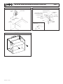
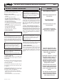
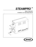
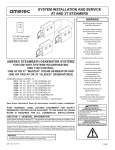
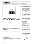
AK and 3K Series Installation and Service
Instructions
WARNING
Possible Controls
Electrical grounding is required on
all AMEREC Steambath Generators.
K60/KT60
All electrical supplies should be
disconnected when servicing
generator.
OR
All wiring must be installed by a
licensed electrical contractor in
accordance with local and national
codes.
K30
OR
R30K
AK GENERATOR
AMEREC STEAMBATH GENERATORS
(AK and 3K MODELS)
Note:To be used with the K30,K60,KT60 or R30K Control.
SAVE THESE INSTRUCTIONS
All plumbing must be installed by a
licensed plumber in accordance with
all applicable local and national
codes.
AK series generators are for indoor
use only.
AK series generators are not for
space heating purposes.
Be certain that steambath enclosures
are properly sealed to avoid water
damage from escaping steam. It is
recommended that 100% silicone
caulk be used to seal all pipes and
fittings. Steam must be prevented
from escaping into the wall cavity.
READ ALL INSTRUCTIONS CAREFULLY BEFORE INSTALLATION.
Never shut off the water to a steam
generator that is in use.
POST "WARNING" LABEL OUTSIDE STEAMBATH FOR SAFETY
WARNINGS. REQUIRED POSTING ON DOOR OF STEAM ROOM
OR ADJACENT TO DOOR FOR ALL COMMERCIAL
INSTALLATIONS.
Electric Shock Hazard - High voltage
exists within this equipment. There
are no user serviceable parts in this
equipment.
WARNING
REDUCE THE RISK OF
OVERHEATING AND SCALDING
SECTION 1: GENERAL INFORMATION
AMEREC Steam Generators are listed by Underwriters Laboratories. The steam generators come assembled
and ready for installation. Check that the size and rating of the generator is suitable for your application, refer
to Steam Room Construction and Generator Sizing Guide (AMEREC document 4211-38).
IMPORTANT
An exhaust fan installed outside the steam
room is strongly recommended to remove
excess steam from the bathroom or shower
area.
4211-143-A
02-19-10
1. Exit immediately if uncomfortable, dizzy or sleepy. Staying too long in
a heated area is capable of causing overheating.
2. Supervise children at all times.
3. Check with a doctor before use if pregnant, diabetic, in poor health or
under medical care.
4. Breathing heated air in conjunction with consumption of alcohol, drugs
or medication is capable of causing unconsciousness.
Do not contact steam head. Stay at least 12" away
from hot steam escaping from the steam outlet.
CAUTION!
REDUCE THE RISK OF
SLIPPING AND FALL INJURY
Use care when entering or exiting the steam room, floor may be slippery.
NOTE: For additional safety instructions, see owner’s manual.
AK and 3K Series Installation and Service Instructions
page 2
Table of Contents
Section
Page
Important Safety Instructions
2
2
Select Mounting Location
4
4
Mounting the Generator
4
Water Quality Requirements
4
4.5
4211-143-A
Description
5
Plumbing Instructions
6
Wiring Instructions
7
-
Electrical Information Chart
8
7
Operational Test
9
8
Service
9
Optional Modifications
10
Trouble Shooting
12-13
-
Exploded Parts Diagram
14-15
-
Wiring Diagram
02-19-10
5-6
9-11
12
16
AK and 3K Series Installation and Service Instructions
IMPORTANT SAFETY INSTRUCTIONS
1. READ AND FOLLOW ALL INSTRUCTIONS.
2. WARNING - To reduce the risk of injury, do not permit children to use this
product unless they are closely supervised at all times.
3. WARNING - To reduce the risk of injury:
a. The wet surfaces of steam enclosures may be slippery. Use care when
entering or leaving.
b. The steam head is hot. Do not touch the steam head and avoid the
steam near the steam head.
c. Prolonged use of the steam system can raise excessively the internal
human body temperature and impair the body’s ability to regulate its
internal temperature (hyperthermia). Limit your use of steam to 10 - 15
minutes until you are certain of your body’s reaction.
d. Excessive temperatures have a high potential for causing fetal damage
during the early months of pregnancy. Pregnant or possibly pregnant
women should consult a physician regarding correct exposure.
e. Obese persons and persons with a history of heart disease, low or high
blood pressure, circulatory system problems, or diabetes should consult
a physician before using a steambath.
f. Persons using medication should consult a physician before using a
steambath since some medication may induce drowsiness while other
medications may affect heart rate, blood pressure and circulation.
4. WARNING - Hyperthermia occurs when the internal temperature of the body
reaches a level several degrees above the normal body temperature of 98.6
degrees F. The symptoms of hyperthermia include an increase in the internal
temperature of the body, dizziness, lethargy, drowsiness and fainting. The effect
of hyperthermia include:
a. Failure to perceive heat:
b. Failure to recognize the need to exit the steambath:
c. Unawareness of impending risk:
d. Fetal damage in pregnant women:
e. Physical inability to exit the steambath: and
f. Unconsciousness.
WARNING - The use of alcohol, drugs or medication can greatly increase the
risk of hyperthermia.
SAVE THESE INSTRUCTIONS
4211-143-A
02-19-10
page 3
AK and 3K Series Installation and Service Instructions
DIAGRAM
3/8" FROM
WALL
1
DIAGRAM 2
WATER SHUT-OFF VALVE
1/2" NPT FITTING
OPTIONAL FILTER
DO NOT CONNECT TO WATER
SUPPLY WITH SADDLE FITTING
1/2" STEAM LINE TO ROOM
UNION
PRESSURE RELIEF VALVE
1-3/8"
DIAMETER HOLE
page 4
3/8" COMPRESSION
ADAPTER
1/2" NPT MALE x
SWEAT ADAPTER
BALL VALVE
6" FROM
TOP OF TUB
UNION
OR 12"
FROM FLOOR
13" SERVICE
CLEARANCE
1/2" NPT MALE x
SWEAT ADAPTER
UNION
DIAGRAM
4211-143-A
02-19-10
3
AK and 3K Series Installation and Service Instructions
SECTION 2:
SELECT MOUNTING LOCATION
page 5
WARNING
SEE DIAGRAMS
The AMEREC steam generator can be hung on a wall
or sit on its base. The best mounting location will
satisfy all or most of the following:
4. The generator should be installed in a dry, well
ventilated area. Suggested locations are under a
vanity, in a closet, attic, crawl space or basement.
1. The steam line should slope to allow condensation
to drain. Condensation should drain into the steam
room.
5. The location should provide clearance for service
and element removal. See diagram 2.
2. The steam line should be less than twenty feet
long. Ten feet is preferred. Steam lines over twenty
feet long should be insulated.
3. The mounting location should minimize the number of bends and elbows in the steam line.
Do not mount outdoors.
Protect from freezing.
Unit must be located as to allow
access for service.
6. The mounting location should allow for a drain hook
up.
7. The generator must be mounted in a minimum 7
cubic foot space.
The generator will not operate
properly, unless it is mounted level
with the arrows pointed up.
8. The generator should not be mounted in an area
subject to freezing.
SECTION 4: MOUNTING THE GENERATOR
SEE DIAGRAM
Wall Mounting:
1. Note the location of the mounting holes on the
back of the generator. The screws must set directly
into studs or equivalent supports. Drill pilot holes on
16" centers and install the two #10 1½" screws
provided.
Floor Mounting:
1. In general the width of the unit allows it to sit on
a shelf, across the ceiling joists or on a floor. The
generator must be restrained from moving. Normally
the piping will provide adequate support. If not,
additional support must be provided.
2. Carefully hang the generator on the two screws.
Tighten the screws. Replace the front cover. Secure
the front cover with six screws.
2. All floor installed generators must have provision
for routine draining of the tank.
SECTION 4.5: Water Quality Requirements
The nature of a boiler or steambath generator requires testing of the feedwater to avoid potential
high concentrations of impurities which can cause a deposit or scale to form on the internal surfaces. This deposit or scale can interfere with the equipments proper operation and even cause
premature boiler or generator failure. Concentration of impurities is generally controlled by treating the feedwater and or "blowing down" the generator or boiler when it is not heating. The "blow
down" process involves removing a portion of the tank water with high solid concentration and
replacing it with makeup water.
To insure proper operation, the water supply should be tested prior to operating the equipment.
There are several treatment processes which can be used if you have a problem with hard water.
A local reliable water treatment company can recommend the appropriate treatment if required.
The recommended feedwater quality is listed below.
Feedwater Quality
Hardness, ppm
T-Alkalinity, ppm
Silica Range, ppm
PH (strength of alkalinity)
10 - 30 (.5 - 1.75 gpg)
150 - 700 (8.75 - 40.8 gpg)
15 - 25 (1.28 - 1.45 gpg)
10.5 - 11.5
IMPORTANT! Regular maintenance will help your steamer work properly for a
long time. Check for leaks, loose or damaged wires, signs of corrosion and
calcium build up in the tank on the level probe.
This is particularly important in areas with high calcium levels and other water
quality problems. Calcium build can cause poor steamer performance and
damage the heating elements!
Do not put a shut off valve in the
steam line. Avoid traps and valleys
where water could collect and cause a
steam blockage. The hot steam line
must be insulated against user
contact.
Centering the steam pipe is critical in
rooms made of plastic, acrylic, resin,
fiberglass or similar materials.
Allowing the steam pipes to touch
materials not rated for 212 degrees
Fahrenheit or higher will result in
damage to these materials.
Do not install the steam head near
bench(es) or where steam may spray
or where condensation will drip on
the user as this will present a scald
hazard.
The steam pipe entry and any other
entry into the steam room must be
caulked to avoid damage caused by
steam leakage into the wall.
4211-143-A
02-19-10
AK and 3K Series Installation and Service Instructions
DIAGRAM 5
page 6
DIAGRAM 6
3/8" FROM
WALL
1/2" NPT FITTING
1 3/8"
DIAMETER
HOLE
1/4"
1/2" NPT
SWEAT
ADAPTER
S
P
A
C
E
R
CENTER IN
OPENING
STEAM HEAD INSULATOR
S
T
U
D
FRAGRANCE
RESERVOIR
1/4"
1-3/8" DIAMETER HOLE
STEAM HEAD
DIAGRAM 8
DIAGRAM 7
6" MIN -
ESCUTCHEON
MOUNTING
BRACKET
TEMPERATURE
SENSOR
(K60 or K30 only)
CONTROL
HOUSING
STEAM
CONTROL
(4 feet up not directly
over steamhead)
7'
MAX
TEMPERATURE
SENSOR CABLE
(K60 or K30 only)
CONTROL
CABLE
2" DIAMETER
HOLE IN FINISHED
WALL
CONTROL HOUSING
MOUNTING SCREWS
(DO NOT OVER
TIGHTEN)
DIAGRAM 9
DECORATIVE CONTROL
COVER PLATE
DIAGRAM 10
TEMPERATURE SENSOR PLUG (J4)
OPTIONAL AUTOMATIC
DRAIN CONNECTION
S30
S60A
S60B
CONTROL
HOUSING
STEAM
CONTROL
STEAM CONTROL PLUG
R30K (S30)
K30 PRIMARY (S30)
KT60/K60 PRIMARY (S60A)
KT60/K60 SECONDARY (S60B)
SEALANT
(MUST FILL GROUT
LINE FOR TILE
WALLS).
4211-143-A
02-19-10
TEMPERATURE
SENSOR
(K60 or K30 only)
AK and 3K Series Installation and Service Instructions
SECTION 5: PLUMBING INSTRUCTIONS
SEE DIAGRAMS
All plumbing shall be installed by a licensed plumber
and conform with local & national codes.
Materials (locally available):
- 3/8" O.D. copper tube for the water supply to the
generator.
- 3/8" water supply shut-off valve.
- 3/8" supply valve housing and filter (optional
depending on local water conditions).
- 3/8" O.D. compression to 3/8" male NPT adapter.
- 1/2" copper sweat unions. (2)
- 1/2" copper pipe for the tank drain.
- 1/2" copper pipe and 1/2" female NPT sweat adapter
for the steam line between the generator and the
steam room.
- 3/4" copper pipe, fittings, and a sweat union for
the Pressure Relief Valve drain.
- Tube DAP 100% silicone caulk.
- Rectorseal No. 5 pipe compound.
1. INSTALL WATER LINE
IMPORTANT
Maximum recommend input water pressure not to
exceed 100 PSI.
Run 3/8" copper tube between the nearest cold water
line and the WATER INLET fitting on the generator.
Locate a shut-off valve near the generator. Connect
this line to the generator with a 3/8" compression
adapter. When tightening this fitting always use two
wrenches so there will be no strain on the water inlet
valve.
IMPORTANT
If the generator is mounted in a place difficult
for the home owner to access, the water
supply shut- off valve should be located where
it can be quickly accessed in an emergency.
IMPORTANT
Do not use a saddle valve or saddle fitting for
the water shut-off valve.
Flush water supply line before final hookup.
2. INSTALL STEAM LINE
A. At the generator: Install a 1/2" male NPT sweat
adapter directly into the tank. Install a 1/2" union in
the steam line.
B. Run the 1/2" copper steam line from the generator
to the steamroom. Refer to SECTION 2: SELECT
MOUNTING LOCATION.
C. The steam line should enter the steam room 12"
above the floor or at least 6" above a tub rim or ledge.
See diagram 1.
D. At the steam room: Drill/prepare a 1-3/8" hole for
the steam line entry. Center the 1/2" copper steam
pipe in the 1-3/8" hole. See diagram 5.
- Terminate the steam line with a 1/2" NPT male
adapter. Stub the line out into the room 3/8" from
the finished surface.
- Secure the steam line to a structural member.
4211-143-A
02-19-10
IMPORTANT
If the steam line is in an area where the
temperature will be below 40 degrees Fahrenheit or if the line is more than 20 feet long, best
results can be obtained by insulating the
steam pipe.
3. INSTALL STEAM HEAD INSULATOR: Apply silicone caulk to the finished wall side of the steam head
insulator and screw on hand tight until it is flush with
the wall with the opening pointing down. If a hand
tight fit does not align with the opening pointing
down, use teflon tape on the steam line threads to
adjust the fit.
4. INSTALL STEAM HEAD AND ESCUTCHEON: Place
the escutcheon over the steam head insulator then
slide the steam head on until the escutcheon rests
firmly against the finished wall. Tighten the hex head
screw underneath the steam head to secure it in place
with the allen wrench provided. The steam head
should be level with its fragrance reservoir at the top.
See diagram 6.
page 7
WARNING
Do not connect the overpressure
device output into the steam line.
Do not connect the drain valve into
the steam line.
Do not mount outdoors.
Protect from freezing.
Unit must be located as to allow
access for service.
The generator will not operate
properly, unless it is mounted level
with the arrows pointed up.
IMPORTANT
Check all of the standard fixtures in the steam
room. All fixture penetrations must be sealed
with 100% silicon caulk to avoid moisture
damage within walls.
5. INSTALL PRESSURE RELIEF VALVE
Install the pressure relief valve into its port on the
generator. The pressure relief valve outlet must drain
in accordance with local and national codes.
6. INSTALL DRAIN VALVE
Install 1/2" NPT male sweat adapter directly into the
tank as shown in diagram 2. Install a 1/2" union. Run
a 1/2" copper drain line to a gravity flow drain. Do not
run the drain uphill. The drain must be connected in
accordance with local and national codes. See diagram 2.
Do not put a shut off valve in the
steam line. Avoid traps and valleys
where water could collect and cause a
steam blockage. The hot steam line
must be insulated against user
contact.
Centering the steam pipe is critical in
rooms made of plastic, acrylic, resin,
fiberglass or similar materials.
Allowing the steam pipes to touch
materials not rated for 212 degrees
Fahrenheit or higher will result in
damage to these materials.
Do not install the steam head near
bench(es) or where steam may spray
or where condensation will drip on
the user as this will present a scald
hazard.
The steam pipe entry and any other
entry into the steam room must be
caulked to avoid damage caused by
steam leakage into the wall.
AK and 3K Series Installation and Service Instructions
SECTION 6: WIRING INSTRUCTIONS
page 8
WARNING
SEE ELEC. INFO. CHART AND WIRING DIAGRAM
1. CONTROL CABLE ROUGH-IN
The low voltage control can be mounted up to 25 feet
from the generator either inside or outside the steam
room for the K30, K60 or R30K control but with a built
in temperature sensor, the KT60 must be mounted
inside the steam room, also see #6 optional secondary generator control. String the 25' cable from the
control location through 1/2" holes in the wall studs
or ceiling joists to the generator. Note: Do not staple
through or damage cable. Use factory supplied cables
only. Optional for tile rooms, a 2 gang rough-in box
may be installed at the desired control mounting
location. A mounting plate with proper diameter hole
is included with the control kit. Tile up to the hole in
mounting plate as indicated in diagram 13 or 14.
2. TEMPERATURE SENSOR CABLE ROUGH-IN
(REQUIRED FOR K60 OR K30 ONLY)
It is recommended that the sensor be mounted in the
steam room 6" from the ceiling, but not directly over
the steam dispersion head or more than 7 feet above
the floor. String the sensor cable from the sensor
location through 1/2" holes in the wall studs or ceiling
joists to the generator location. Leave 12" of slack at
the sensor location. Note: Do not staple through or
damage cable. Use factory supplied cables only.
3. ELECTRICAL ROUGH-IN
Size wire for the generator as indicated by the Electrical Information Chart on page 8. Use correct size
and type to meet electrical codes. Leave 4 feet of
slack wire at generator location for finish hookup.
Connect the generator to a dedicated circuit breaker.
A GFI device is not required by UL. One may be
installed if required by local codes or the owner. A GFI
device will tend to nuisance trip due to heater element
aging.
4. ELECTRICAL FINISH
Materials (locally available):
- 3/4" Strain relief for supply wire.
A. Route the copper supply wire with appropriate
strain relief through the hole marked POWER ENTRY.
B. Connect the supply wires to terminals marked L1
and L2.
C. Connect the ground to the ground lug (green
screw).
4211-143-A
02-19-10
5. INSTALL GENERATOR CONTROL (K30,K60,KT60)
The low voltage controls can be mounted directly to
a finished wall either inside or outside the steam
room with the exception of the KT60 control which
must be mounted inside the steam room. Using a 2"
hole saw, drill a hole in the finished wall where the
control is to be mounted (the control cable should
already be roughed-in to this location). With the
decorative cover removed from the control switch
assembly, insert the two control mounting screws
through the control housing (may need to punch
through skinned holes) and screw 1/4" into the mounting bracket. Locate the control cable and plug it into
the back of the control housing. See diagram 8. Run
a bead of 100% silicon caulk in-between the 2 ridges
around the perimeter on the back of the control
housing. See diagram 9. Insert the mounting bracket
into the wall cavity by first pushing with the control
housing and then with a hard flat surface on the
control housing mounting screws which extend out
through the control face. Once the mounting bracket
has been inserted into the finished wall, center the
control and tighten the mounting screws to draw the
control housing securely against the finished wall.
Do not over tighten the mounting screws. Install the
decorative cover plate by sliding the top of the cover
plate over the tab on the top of the control housing
and pushing on the bottom of the cover plate to
complete the snap fit. See diagram 11. Route the
generator end of the control cable through the generator hole marked CONTROL WIRING ENTRY using
the strain relief provided. Plug the control cable into
the connector on the printed circuit board assembly.
Insert cable into connector S30 if a K30 control is
used or connector S60A if a K60 or KT60 control is
used. See diagram 10.
5A. INSTALL GENERATOR CONTROL (R30K)
The low voltage control can be mounted directly to a
finished wall either inside or outside the steam room.
Using a 1-3/4" hole saw, drill a hole in the finished
wall where the control is to be mounted (the control
cable should already be roughed-in to this location).
Locate the control cable, pull it out through the
1-3/4" hole and plug the connector on the back of the
control housing. Run a bead of 100% silicone caulk
around the perimeter on the back of the control
housing. See diagram 13. Insert the control into the
wall cavity.
The pressure relief valve must be
installed in such a fashion that the
risk of scalding is reduced to a
minimum. Draining the pressure
relief valve into the steam room may
present a scald hazard.
Boiling water may be discharged from
the drain. Proper precaution should
be taken too insure safety.
Draining the tank into the steam room
may present a scald hazard and/or
damage materials used to construct
the steam room.
Electrical shock hazard - Disconnect
all electrical power before servicing
the generator. All wiring should be
installed by a licensed electrical
contractor in accordance with local
and national codes.
The generator is designed for hookup
with copper wire only.
AK and 3K Series Installation and Service Instructions
page 9
DIAGRAM 12
DIAGRAM 11
USED WITH K60 OR K30 CONTROL ONLY
WALL
SILICONE
CAULK
WALL
DECORATIVE
CONTROL COVER
PLATE
TEMPERATURE
SENSOR
(BUILT-IN SENSOR ON KT60
CONTROL ONLY)
PROBE MUST
BE POINTED
DOWN
PIGTAIL
SENSOR
CABLE
CONTROL
HOUSING
7/8" HOLE
ELECTRICAL INFORMATION CHART
STEAM
GENERATOR
MODEL NO.
AC
VOLTAGE
PHASE
AK4
208 / 240
1
3,000
4,000
14.5
17.0
20
25
10-2 W/G
AK5
208 / 240
1
3,750
5,000
18.0
21.0
25
30
10-2 W/G
AK6
208 / 240
1
4,500
6,000
21.7
25.0
30
35
8-2 W/G
AK7
208 / 240
1
5,250
7,000
25.3
29.0
35
40
8-2 W/G
AK8.5
208 / 240
1
6,375
8,500
30.7
35.5
45
50
6-2 W/G
AK10
208 / 240
1
7,500
10,000
36.1
41.5
50
60
6-2 W/G
AK12
208 / 240
1**
9,000
12,000
28.8/14.4
33.3/16.7
40/20
50/25
6-2/10-2 W/G
AK14
208 / 240
1**
10,500
14,000
32.5/18.0
37.5/20.8
50/25
50/30
6-2/10-2 W/G
3K8
208
3
7,900
-
21.9
-
30
-
10-3 W/G
3K10
208
3
10,100
-
28.1
-
35
-
8-3 W/G
3K12
208
3
11,300
-
31.3
-
40
-
8-3 W/G
3K14
208
3
14,500
-
40.2
-
50
-
6-3 W/G
NOMINAL
@208
WATTAGE
@240
NOMINAL AMPERAGE
@208
@240
UL RECOMMENDED
PROTECTIVE DEVICE
@208
@240
RECOMMENDED
MINIMUM COPPER
SUPPLY WIRE*
* Observe wire sizes for 208 VAC installations. 208 VAC wired units must be supplied with a minimum of 195 VAC while operating (heating). Unit is rated for copper
wire only. All wire is UL approved 300V 75 deg. C minimum unless otherwise specified. ** Single phase AK12 & AK14 require two seperate line feed circuits.
DIAGRAM 14
DIAGRAM 13
R30K
ROUGH-IN
K30, K60, KT60
ROUGH-IN
(OPTIONAL NUT IF BACK OF
WALL IS ACCESSABLE)
APPLY SEALANT
(100% SILICONE CAULK)
2 GANG ROUGH-IN BOX
TILE UP TO
1-3/4" DIAMETER HOLE
IN FINISHED WALL
4211-143-A
02-19-10
TILE UP TO 2"
DIAMETER HOLE
IN FINISHED WALL
AK and 3K Series Installation and Service Instructions
SECTION 6: WIRING INSTRUCTIONS
(continued)
SEE DIAGRAM
6. OPTIONAL SECONDARY GENERATOR CONTROL
As an option, a second K60 control can be installed
with an AK generator to provide ON/OFF control both
inside and outside the steam room. The second
control should be installed as described in paragraphs 1 & 5, with the second control cable plugged
into connector S60B for the K60 Control on the
printed circuit board assembly. See diagram 10.
7. INSTALL TEMPERATURE SENSOR
(REQUIRED FOR K60 OR K30 ONLY)
The temperature sensor should be mounted 6" below
the ceiling, inside the steam room, but not directly
over the steam dispersion head or more than 7 feet
above the floor. Using a 7/8" hole saw, drill a hole in
the finished wall where the sensor is to be mounted
(the sensor cable should already be roughed-in to
this location). Locate the sensor cable, pull it out
page 10
WARNING
through the hole and plug it into the temperature
sensor. It is best to tape the sensor and cable connection together to avoid disconnection inside the wall.
Apply silicon caulk as shown in diagram 12 and insert
the sensor in the hole. Make sure that the sensor
probe is pointing down once installed. Tape the
sensor in place while the silicone hardens. Route the
generator end of the sensor cable through the generator hole marked CONTROL WIRING ENTRY using
the control cable strain relief. Plug the sensor cable
into the connector marked J4 on the printed circuit
board assembly. See diagram 10
SECTION 7: OPERATIONAL TEST
1. Assure power and water are on.
2. Press the ON/OFF. The control should light-up.
3. Allow 10 minutes for the steam to start.
4. Once the steam starts, press the ON/OFF. The
steam should stop; there shouldn't be any water
flow. The control should not be lit-up.
5. Press the ON/OFF. The control should light up.
6. Within one minute the unit should again produce steam. It should call for water once every two
minutes or more depending on its power rating.
It’s normal for the flow of steam out the steam
head to slow for up to 10 seconds each time the
unit calls for water.
7. The unit will shut down automatically in 30
minutes if the "R30K or K30" Control is used, or up
to 60 minutes if the K60 or KT60 Control is used.
When the time runs out the steam will stop and
there should not be any water flow. The control
should not be lit.
8. If the unit does not operate as described above,
refer to SECTION 9: TROUBLESHOOTING GUIDE.
THE UNIT IS NOW READY FOR OPERATION.
SECTION 8: SERVICE
SEE ELECTRICAL INFORMATION CHART
1. DESCRIPTION OF AMEREC AK SERIES
GENERATOR
2. MAINTENANCE OF AK SERIES STEAM
GENERATORS
The AK series is one of AMEREC’s high performance
line of steam generator products.
- VISUAL INSPECTION - Whenever the generator is
opened, inspect for any evidence of water leaks.
Inspect the wiring for any evidence of overheating.
Check all electrical connections for tightness.
The Printed Circuit Assembly (the “PCA”) provides
the basic functions necessary to produce steam. The
PCA controls makeup water, provides a water level
permissive for powering the elements and provides
raw DC power for the system.
The PCA also provides regulated non-interruptible
5.0 VDC power for the generator control and temperature sensor. It provides the interface circuitry
between the control and the PCA, provides the room
temperature control loop, power switching for "soft
steam" and a fixed 30 minute steam bath timer or
adjustable 60 minute timer.
- FLUSH TANK - Flush monthly, or more often,
depending on local water conditions.
- FLUSHING PROCEDURE:
1. The generator should be cool.
2. Press the ON/OFF. The control should light.
3. Open the manual drain valve.
4. The unit will drain without heating the water.
5. Allow the water to run for a full 10 minutes, then
press the ON/OFF. The control light should turn off.
(continued page 9)
4211-143-A
02-19-10
Electrical shock hazard - Disconnect
all electrical power before servicing
the generator. All wiring should be
installed by a licensed electrical
contractor in accordance with local
and national codes.
For continued safe operation use
factory authorized replacement
elements only.
AK and 3K Series Installation and Service Instructions
DIAGRAM 15
DIAGRAM 16
page 11
DIAGRAM 17
VERTICAL ± 15°
ELEMENT END
ORIENTATION
RUBBER
GASKET
LEVEL PROBE
1/8" TO 3/8"
GASKET
HEAT
ELEMENT
DIAGRAM 18
DIAGRAM 19
NOTE TAB
OFFSET IN
OPENING
This diagram intentionally left blank.
REF
FAST-ON TM
LUG
DIAGRAM 20
4211-143-A
02-19-10
AK and 3K Series Installation and Service Instructions
SECTION 8: SERVICE
(continued)
SEE DIAGRAMS
6. Allow the unit to drain completely. When the water
stops, close the manual drain valve.
3. REPAIR OF AK SERIES GENERATORS
A. ELEMENT REPLACEMENT:
Disconnect power from the unit. Drain the tank. Open
the front and HEATING ELEMENT ACCESS covers.
Note the wire connections. See diagram 15. Remove
the element wires. Using a hot water element socket,
remove the element. To install a new element, mount
a new element gasket on the element. Clean the
element port and add a light coat of Rectorseal No. 5
pipe thread compound to the threads. Insert and
hand tighten the element-gasket combination. Notice
the element end orientation as shown in diagram 16.
Tighten the element until the orientation is the same
as diagram 16, ± 15°. The gasket should be set and
tight but not deformed to a rounded or bulbous
appearance. If the drain valve was removed reinstall
it. Reconnect the wiring. Test the unit per SECTION 7:
OPERATIONAL TEST. Check for leaks at the element.
Replace the front cover and the HEATING ELEMENT
ACCESS cover.
B. PRINTED CIRCUIT REPLACEMENT:
Printed circuit assembly (PCA) removal and replacement must be performed in the sequence described
below. Any other method can damage the PCA.
IMPORTANT
The PCA’s contain static sensitive devices.
Static electricity may damage PCA’s. Handle
accordingly.
Disconnect power from the unit. Note and tag the
positions of all wires that plug into the printed circuit
assembly mounted relays. Remove all the wires from
the relays. When removing these wires, pull on the
connector, not the wire. Note the blue wire connected
to the shortest of the triple pronged water level probe.
Disconnect all three wires from the water level probe.
Remove PCA from all seven standoffs by pinching the
tops. When it is completely disconnected, it may be
lifted out of the enclosure. See diagram 20. To install
the board, reverse this procedure. Test the unit per
SECTION 7: OPERATIONAL TEST.
IMPORTANT
The blue wire connected to “L” on the
PCA must be connected to the shortest of the
three level probes.
C. WATER SOLENOID REPLACEMENT:
Disconnect power from the unit. Turn the water
supply OFF. Disconnect the water supply from the
water solenoid valve. Remove the front cover. Remove the two blue wires from the water solenoid
valve. Rotate the self-tightening hose clamp so it can
be loosened with a pair of pliers. Squeeze the clamp
and move it down towards the shelf and off the valve
outlet tube. Remove the two 1/4" - 20 hex head bolts
and lock washers that attach the valve to the chassis.
Pull the valve off the rubber fill hose. To install the
valve, reverse these instructions. Test the unit per
SECTION 7: OPERATIONAL TEST.
4211-143-A
02-19-10
D. LEVEL PROBE REPLACEMENT:
Disconnect power from the unit. Remove the front
cover. Note where the blue wire is connected to the
triple pronged water level probe. Disconnect all three
wires from the water level probe. Using a 1-1/4" box
wrench, remove the level probe. Install a new level
probe. Use Teflon Tape on threads of probe if required. Tighten until the bottom of the plastic nut is
1/8" to 3/8" inch above the top of the port. See
diagram 17. Reattach the three wires. Test the unit
per SECTION 7: OPERATIONAL TEST.
IMPORTANT
The blue wire connected to “L” on the
PCA must be connected to the shortest of the
three level probes.
IMPORTANT
The level probe may be extremely tight. Damage
to the insulation or chassis may result unless the
tank is properly blocked or supported during
probe removal or installation. It may be necessary to completely disconnect and disassemble
the generator.
page 12
WARNING
All electrical supplies should be
disconnected when servicing
generator.
Electrical Shock Hazard. PCA’s have
exposed 208 / 240 VAC on them.
Disconnect 208 / 240 VAC power to
the generator before servicing.
The relays may be damaged if the
correct orientation of the connectors
is not observed. See diagram 19.
AK and 3K Series Installation and Service Instructions
page 13
SECTION 9: OPTIONAL MODIFICATIONS
The AK Generator design may incorporate several modification options. Options such as automatic tank draining and others are available. Please call the AMEREC
Service Department at 1-800-331-0349 for instructions and availability of these options.
SECTION: 10 TROUBLE SHOOTING GUIDE
There are no user serviceable parts in the Generator. All repair should be performed by a qualified service person. For additional assistance or the factory authorized
service person nearest you call the AMEREC Service Department at 1-800-331-0349. The Trouble Shooting Guide below is meant as a general aid only. Follow ACTION
TO BE TAKEN in order until the problem is resolved. Where replacements or repairs are indicated, see the appropriate paragraph of SECTION: 8 SERVICE.
SYMPTOMS
Control won't turn "ON"
(Control light off).
Note: Control Cables must
be correctly plugged in
before power is turned on.
Control "OFF". (Control light
off)
Water won't shut off and runs
out of the steam head.
PROBABLE CAUSES
Improper power supplied (no power).
or
Control improperly connected.
or
"PCA" printed circuit assembly is faulty.
or
Control cable is faulty.
or
Contol is faulty.
Water solenoid valve is stuck open.
or
"PCA" printed circuit assembly is faulty.
ACTION TO BE TAKEN
1. a. Make sure circuit breaker is "ON", 208/240V supplied.
b. Using a voltmeter, check the voltage across the two fuses on the "PCA"
printed circuit assembly. Voltage should be 208V to 240V.
c. Check fuses on the PCA. If fuse(s) are blown, replace with Buss#
MDL 10/100 or equivalent fuse. If the fuse blows again - call AMEREC's
Service Department.
2.
Turn off power to the generator.
3.
Check control(s) installed per Section 6-5. Re-apply power and test operation.
4.
Replace PCA printed circuit assembly - call AMEREC's Service Department.
5.
Replace control cable - call AMEREC's Service Department.
6.
Replace the control - Call AMEREC's Service Department.
1. Turn off power to the generator. If the water stops, go to step 3.
2. a. Remove the water solenoid valve, dissassemble, clean,
re-assemble, and check for proper operation.
b. Replace valve - call AMEREC's Service Department.
3. Replace the "PCA" printed circuit assembly - call AMEREC's Service Department.
Control "ON". (Control light
on)
Water won't shut off and runs
out of the steam head.
Control "ON" (Control light
on), Tank drained.
Unit won't fill.
"PCA" printed circuit assembly is faulty.
or
Connection between the blue wire and the
water level probe is faulty.
1. Check that the blue & white wires are properly attached to the water level probe.
Blue wire to the shortest level probe,white to the highest probes.
No water supplied (turned off?)
or
Plugged water solenoid valve.
or
Water solenoid valve is faulty.
or
"PCA" printed circuit assembly is faulty.
or
Level probe is faulty.
1. Check for proper water supply (Supply valve "on"). Check for closed drain valve.
2.Replace the "PCA" printed circuit assembly - call AMEREC's Service Department.
2. Remove the blue wire from the level probe. If the unit fills, clean or replace the
level probe.
3. Reconnect the blue wire to the shortest level probe. At the water valve solenoid,
slide back the blue connector enough to get the voltmeter probes on the
solenoid terminals. Measure the voltage across the solenoid terminals. If it is
not 208V / 240V, replace the printed circuit assembly. If 208V / 240V is found
proceed with steps 4 & 5.
4. Remove water solenoid valve; disassemble, clean, reassemble, and check for
proper operation.
5. Replace the water solenoid valve - call AMEREC's Service Department.
4211-143-A
02-19-10
AK and 3K Series Installation and Service Instructions
page 14
SECTION 10: TROUBLE SHOOTING GUIDE cont.
SYMPTOMS
Control "ON". (Control light
on)
Unit won't steam.
Note:
Steam lit steadily on K30
or
Time/Temp properly
displayed on K60/KT60
PROBABLE CAUSES
Unit has not filled completely.
or
Heating elements burnt out.
or
Level probe faulty.
or
"PCA" printed circuit assembly is faulty.
ACTION TO BE TAKEN
1. a. Push the control "OFF".
b. Open the drain valve allowing tank to drain completely.
c. Close the drain valve.
d. Push the control "ON".
e. Unit will begin filling, listen for a click noise. Within 20 seconds after
click noise is heard, the water fill will shut off. This will indicate the
tank is full. Go to step 4, if the tank does not fill - See SYMPTOMS:
"Unit won't fill up".
2. If the tank filled but the relay click was not heard, temporarily ground the
two long probes. If the click is heard as each probe is grounded, replace the
level probe. If the click is not heard replace the "PCA" printed circuit assembly.
3. After it has been determined that the tank has filled and the click noise was
heard, remove the heating element access panel. Using a voltmeter, check the
voltage between the two wires on each heating element - the voltage should be
208V. If proper voltage is found call the factory for replacment heating
elements. If no voltage is found - check wiring diagram - call AMEREC's
Service Deparment.
Control "ON".
K60/KT60 Control displays
"E001"
Temperature sensor not connected.
Control "ON".
K60/KT60 Control displays
"E002"
Temperature sensor
or
cable shorted.
Control "ON".
K60/KT60 Control displays
">>>º"
Steambath temperature over 132 º
or
Sensor/cable faulty.
Control "ON"
K30 light blinking
Control won't turn "OFF"
(Control light off).
Control "OFF"
Unit won't shut off.
Water continually sputters
out of steam head.
Unable to adjust Time or
Temp setting with
K60/KT60
4211-143-A
02-19-10
Control improperly connected.
or
Sensor/cable faulty.
or
Control faulty.
Control is faulty.
"PCA" printed circuit assembly is faulty.
1. Check that the sensor cable is connected to J4 on the "PCA" printed circuit
assembly.
2. Check the cable connection to the temperature sensor.
3. Replace sensor and/or cable - call AMEREC's Service Department.
1. Check sensor cable for damage from nail/staple puncture.
2. Check sensor cable ends for frayed/exposed wire strands.
3. Replace sensor and/or cable - call AMEREC's Service Department.
1. If bath is too hot, shut off circuit breaker and call AMEREC's Service
Department.
2. Treat as "E002" fault above.
1. Check that the control cable is properly plugged in at the control and at the
generator. K30 to primary S30 connector on the PCA. Turn off power supply,
wait one (1) minute then turn back on. Check for proper operation. If K30 is
still "blinking", turn off power supply and call AMEREC's Service Department.
2. Check sensor/cable as with K60 "E001" and "E002"
3. Replace K30 Control - call AMEREC's Service Department.
1. Replace the control - call AMEREC's Service Department.
1. Turn off the power to the generator, replace printed circuit assembly - call
AMEREC's Service Department.
Foaming contaminants in the water.
1. Flush tank 3 times. See section 8, flushing procedure.
2. Call AMEREC's Service Department.
Control faulty
or
"PCA" printed circuit assembly is faulty.
1. Replace control - call AMEREC's Service Department.
2. Replace PCA - call AMEREC's Service Department.
AK and 3K Series Installation and Service Instructions
page 15
!
! !
OR
! "
! '
44
" "
! #
! $
!
#
'
&
'
$
" !
%
"
"
%
&
#
$
&
'
"
4211-143-A
02-19-10
!
AK and 3K Series Installation and Service Instructions
NUMBER
PART NAME
DESCRIPTION
PARTS AND / OR RETURNS:
1
FRAME
CHASSIS
2
TERMINAL
POWER INPUT TERMINAL BLOCK
3
COVER
FRONT WITH WD LABEL
4
COVER
ELEMENT ACCESS
5
TANK
TWO ELEMENTS
6
INSULATION
BLANKET
7
BRACKET
L BRACKET
8
NIPPLE
DRAIN NIPPLE
9
TERMINAL
OPTIONAL AUTO FLUSH TERMINAL BLOCK
11
CAP
CAP, THREAD PROTECTOR
12
LABEL
UL RATING
13
PROBE
TRIPLE LEVEL
14
ELEMENT
REPLACEABLE ELEMENT
15
VALVE
WATER INLET
16
CLAMP
SELF-TIGHTENING
17
HOSE
WATER
18
CLAMP
AUGER
19
VALVE
MANUAL DRAIN
20
GASKET
ELEMENT
21
BRACKET
MOUNTING BRACKET
22
VALVE
PRESSURE RELIEF
23
PCA
PRINTED CIRCUIT ASSEMBLY, AK
24
LUG
GROUND
28
BOLT
1/4-20 x 1/2"
29
WASHER
1/4" LOCK
• For assistance or parts ordering,
please contact your local AMEREC
Dealer or AMEREC at 1-800-331-0349.
Please help us to serve you better by:
1. Identifying the problem by using the
troubleshooting guide in this manual.
• Do not return any material to
AMEREC without first contacting
AMEREC for a Return Authorization
Number. Freight must be prepaid to
AMEREC.
33
CONTROL HOUSING
CONTROL HOUSING
CABLE
CONTROL CABLE
35
SENSOR
TEMPERATURE SENSOR (K30 or K60 ONLY)
36
CABLE
TEMPERATURE SENSOR CABLE
37
STEAM HEAD
DISPERSION HEAD (NOT SHOWN)
38
PLACARD
SAFETY (NOT SHOWN)
39
LABEL
WIRE DIAGRAM
40
FUSES
15/100 SLO-BLO (NOT SHOWN)
41
FUSES
3A SLO-BLO (NOT SHOWN)
43
STANDOFF
STAND OFF
44
COVERPLATE
DECORATIVE CONTROL COVER PLATE
02-19-10
2. Read Number 12, the UL Ratings
Label, to obtain your unit's model and
code number.
• When ordering parts, please provide
the number, description and quantity
needed. When ordering wires or wire
assemblies, please describe the wires
by color, location and / or their
connection points.
34
4211-143-A
page 16
(K30 or K60 ONLY)
AK and 3K Series Installation and Service Instructions
4211-143-A
02-19-10
page 17
AK and 3K Series Installation and Service Instructions
4211-143-A
02-19-10
page 18
AK and 3K Series Installation and Service Instructions
page 19
P.O. Box 2258, Woodinville WA 98072
425-951-1120 Fax: 425-951-1130
email address: amerec @ amerec .com
4211-143-A
02-19-10