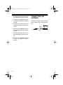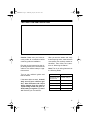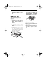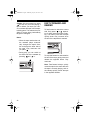
1
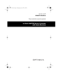
12-2108.fm Page 1 Wednesday, July 14, 1999 10:07 AM
Cat. No. 12-2108
OWNER’S MANUAL
Please read before using this equipment.
In-Dash High-Power AM/FM Stereo Cassette
with Auto-Reverse
12-2108.fm Page 2 Wednesday, July 14, 1999 10:07 AM
FEATURES
Your Optimus In-Dash High-Power
AM/FM Stereo Cassette with AutoReverse has many practical, easyto-use features, and you can install it
in almost any vehicle. The stereo’s
anti-theft control panel lets you
quickly remove it, making the stereo
inoperative.
The auto-reverse cassette deck,
memory tuning, and seek and scan
tuning all help make your stereo’s operation simple and quick so you can
drive safely.
This stereo’s features include:
Anti-Theft Control Panel — lets
you quickly remove and store the stereo’s control panel in the supplied
carry case. This discourages theft
because the stereo cannot operate
without the control panel.
Continuous Auto-Reverse — allows continuous play of both sides of
a cassette tape.
Locking Fast-Forward/Rewind —
lets you quickly move the tape to the
beginning or the end without holding
down either button.
Advanced FM Optimizer Circuitry
— automatically adjusts the tuner’s
stereo separation and high-frequency response to give you the best possible sound, regardless of the signal
level.
Automatic FM Tuning Adjustment
— automatically changes FM reception on weak stations from stereo to
mono, to improve reception of those
stations.
Lighted LCD Display with Clock —
lets you easily see the clock/radio/
cassette deck’s current functions.
Band Button — lets you select the
AM or FM band with the push of a
button.
Seek Tuning — searches forward to
the next strong station in the selected
band.
Automatic Seek Sensitivity — adjusts your stereo so, the first time it
searches a band, it stops only on
strong local stations; the next time it
searches, it also stops on weaker,
distant stations.
© 1995 Tandy Corporation.
All Rights Reserved.
Optimus and Radio Shack are registered trademarks used by Tandy Corporation.
2
12-2108.fm Page 3 Wednesday, July 14, 1999 10:07 AM
Manual/Automatic Memory Programming — lets you manually or
automatically store 12 AM and 18 FM
stations into memory so you can
quickly tune to those stations.
For your records, we recommend
you record your stereo’s serial number below. The serial number is on
the top of the stereo.
Serial Number: ________________
Memory Scan Tuning — scans all
stations in an AM or FM memory
group, playing for 5 seconds on each
station.
Metal/CrO2 Tape Selector — takes
advantage of the improved sound
quality in metal or CrO2 tapes.
Bass, Treble, Fader, and Balance
Controls — let you adjust high and
low sounds and the balance between
the left and right and front and rear
speakers, so you can tailor the sound
to suit your preferences.
Digitally Synthesized Circuitry —
gives you precise tuning and driftfree reception.
Display Color Selector — lets you
change the display’s color to amber
or green.
Built-in Noise Suppression Choke
reduces the noise caused by
your vehicle’s electrical system.
—
3
12-2108.fm Page 4 Wednesday, July 14, 1999 10:07 AM
CONTENTS
Installation ....................................................................................................... 6
Before You Begin the Installation ............................................................... 6
Preparing the Mounting Area ............................................................... 6
Routing Speaker Wire .......................................................................... 6
Making the Connections ............................................................................. 7
Using an Adapter Harness ................................................................... 7
Connecting Ground, Power, and Optional Components ...................... 7
Testing the Power Connections ............................................................ 8
Connecting Speakers ................................................................................. 9
Connecting One Pair of Speakers ....................................................... 9
Connecting Two Pairs of Speakers ...................................................... 9
Connecting the Antenna ........................................................................... 10
Testing the Installation ............................................................................... 11
Mounting the Stereo ................................................................................. 12
Removing the Stereo from the Dash ........................................................ 13
Using the Control Panel .............................................................................. 14
Installing the Control Panel....................................................................... 14
Removing the Control Panel..................................................................... 14
Basic Operation ............................................................................................ 15
Adjusting the Controls .............................................................................. 15
Setting the Clock ...................................................................................... 16
Changing the Display’s Color ................................................................... 16
Using the Radio ............................................................................................. 17
Playing the Radio ...................................................................................... 17
Memory Tuning.......................................................................................... 18
Automatically Storing Stations ............................................................ 18
Manually Storing Stations .................................................................. 19
Selecting a Stored Station ................................................................. 19
Scanning Stored Stations .................................................................. 20
Using the Cassette Player ............................................................................ 21
Playing a Cassette.................................................................................... 21
Fast-Forward and Rewind ......................................................................... 22
4
12-2108.fm Page 5 Wednesday, July 14, 1999 10:07 AM
Care and Maintenance ..................................................................................
The FCC Wants You to Know ...................................................................
Cleaning the Tape-Handling Parts ............................................................
Restoring Tape Tension and Sound Quality..............................................
Replacing Fuses .......................................................................................
Resetting the Stereo .................................................................................
23
23
24
24
24
25
Specifications ................................................................................................ 26
5
12-2108.fm Page 6 Wednesday, July 14, 1999 10:07 AM
INSTALLATION
BEFORE YOU BEGIN
THE INSTALLATION
Preparing the Mounting
Area
Before you install your stereo, read
all the instructions in the “Installation”
section of this manual. You should be
able to answer all of these questions
about your vehicle’s electrical and
sound systems.
Before you mount the stereo, read
through this “Installation” section to
make sure you have all the necessary materials. Then confirm that the
stereo fits your vehicle’s mounting
area.
• Which terminal in my vehicle’s
fuse box is for accessories?
Caution: Be careful to avoid obstructions behind the mounting surface.
• How do I connect a wire to the
fuse box?
Notes:
• Which of the stereo’s wires is
the power wire?
• Which stereo wires are speaker
outputs?
Also, be aware that installation in
your vehicle might require cutting or
modifying your vehicle.
Before you mount the stereo, test the
connections by temporarily connecting the power wires, speakers, and
antenna as described in “Making the
Connections” and install the control
panel as described in “Installing the
Control Panel.” If you plan to use an
adapter harness to connect the stereo, see “Using an Adapter Harness.”
6
• This autosound stereo system is
a DIN-E size unit that requires a
21/8 inches (54 mm) high by 71/2
inches (190 mm) wide by 81/2
inches (216 mm) deep mounting
area.
• If the mounting area is too large,
you might be able to mount the
stereo with an in-dash installation kit, available at your local
Radio Shack store. Follow the
installation kit’s instructions to
mount the stereo.
Routing Speaker Wire
If you install speakers, avoid routing
the speaker wires near moving parts
or sharp edges. You can usually
route it along the wiring channel beneath the vehicle’s door facings by
carefully removing the molding that
holds the carpet in place. After you
route the speaker wires, replace the
molding.
12-2108.fm Page 7 Wednesday, July 14, 1999 10:07 AM
MAKING THE
CONNECTIONS
The supplied 14-wire harness includes all the lead wires you need to
connect the stereo to ground, power,
optional components, and speakers.
You might need additional wire, depending on your individual auto
sound system, to complete the connections. Your local Radio Shack
store carries a full line of wire and
wiring accessories.
Important: Do not cut these wires. If
you cut any wire, you cannot obtain a
refund or exchange on this product.
Radio Shack will provide warranty
service if you cut a wire and find the
product is defective.
Cautions:
• For added safety and to protect
your stereo, disconnect the
cable from your vehicle battery’s
negative (–) terminal before you
begin.
• You must connect the ground,
primary, and memory backup
wires first, then test these connections before you make any
other connections. If you do not
make the connections in the
order shown, damage to the stereo is possible if any wire connections are made incorrectly.
Using an Adapter Harness
If you are replacing an existing stereo
or if your vehicle has been factorywired for autosound components,
you might be able to use an adapter
harness to connect the power and
speakers. Your local Radio Shack
store sells adapter harnesses for
most vehicles.
Follow the directions that come with
the adapter harness to connect power and the speakers.
Connecting Ground, Power,
and Optional Components
Follow these steps to connect the 14wire harness to ground, primary and
memory backup power, and optional
components.
1. Disconnect the cable from your
vehicle battery’s negative (–)
terminal.
2. Connect the black ground wire
to a chassis ground, such as a
metal screw attached to a metal
part of the vehicle’s frame. Be
sure that the screw is not insulated from the chassis by a plastic part.
7
12-2108.fm Page 8 Wednesday, July 14, 1999 10:07 AM
3. Connect the red power wire
(with in-line fuse holder) to a
point in your vehicle’s fuse block
that has power only when you
turn the vehicle’s key to either
the accessory (ACC) or ON
position.
This connection powers the stereo and turns it on when you
turn on the ignition or turn the
key to ACC, and turns off the
stereo when you turn off the ignition. This prevents your vehicle’s
battery from being drained if you
leave the stereo on when you
turn off the ignition.
4. Connect the yellow power/memory wire (with in-line fuse holder)
to your vehicle battery’s positive
(+) terminal or to a point in your
vehicle’s fuse block that provides a continuous source of 12
volts.
This connection provides continuous power for the stereo’s
clock and tuner memory when
the ignition is turned off.
5. Connect the blue/white wire to
any optional component, designed to run from a switched
source, that you want to turn on
and off when you turn the stereo
on and off (such as an equalizer/
booster).
This wire does not provide
power to the component. It simply turns it on or off. If you do not
use this wire, secure it with a
8
wire tie and do not let it touch
metal.
Testing the Power
Connections
Temporarily connect:
• The 14-wire harness into the
stereo’s 14-pin wiring socket
• Your vehicle battery’s negative
(–) cable
Install the stereo’s anti-theft control
panel (see “Installing the Control
Panel”). Then turn on your vehicle’s
ignition. Verify that everything works
properly (the stereo works properly
when the display lights and the frequency or time display appears).
If the stereo does not work, immediately turn off your vehicle’s ignition, then unplug the 14-wire harness and your vehicle battery’s
negative (–) cable. Recheck your
connections.
12-2108.fm Page 9 Wednesday, July 14, 1999 10:07 AM
If the stereo works properly, disconnect:
Then follow these steps to connect
the 14-wire harness to the speakers.
• The 14-wire harness from the
stereo’s 14-pin wiring socket
1. Connect the gray wire to the
right speaker’s positive terminal. This terminal is usually
marked with a plus sign (+) or
red mark.
• Your vehicle battery’s negative
(–) cable
Then proceed with the installation.
CONNECTING
SPEAKERS
You can connect one or two pairs of
speakers to the stereo.
Cautions:
• Be sure your speakers can handle 28 watts of power (14 watts
per channel). Each speaker
must have an impedance of at
least 4 ohms. Your local Radio
Shack store carries a full line of
speakers.
• You must connect a separate
wire to each speaker terminal as
described in the following sections. Do not use a common wire
or chassis ground for any
speaker connection.
Connecting One Pair of
Speakers
If you are using only one pair of
speakers, rotate FADER to its center
position until you feel it click and the
tab on FADER points to the left.
2. Connect the violet/black wire to
the right speaker’s negative terminal. This terminal might be
marked with a minus sign (–) or
it might not be marked at all.
3. Connect the white wire to the left
speaker’s positive terminal.
4. Connect the green/black wire to
the left speaker’s negative terminal.
Connecting Two Pairs of
Speakers
If you are using both front and rear
speakers, follow these steps to connect the 14-wire harness to the
speakers.
1. Connect the gray wire to the
right front speaker’s positive terminal. This terminal is usually
marked with a plus sign (+) or
red mark.
2. Connect the gray/black wire to
the right front speaker’s negative terminal. This terminal might
be marked with a minus sign (–)
or it might not be marked at all.
9
12-2108.fm Page 10 Wednesday, July 14, 1999 10:07 AM
3. Connect the white wire to the left
front speaker’s positive terminal.
4. Connect the white/black wire to
the left front speaker’s negative
terminal.
5. Connect the violet wire to the
right rear speaker’s positive terminal.
6. Connect the violet/black wire to
the right rear speaker’s negative
terminal.
7. Connect the green wire to the
left rear speaker’s positive terminal.
8. Connect the green/black wire to
the left rear speaker’s negative
terminal.
10
CONNECTING THE
ANTENNA
Connect the vehicle’s antenna cable
to the stereo’s large, black antenna
jack.
Antenna
Connector
Vehicle’s Antenna
Back of Stereo
12-2108.fm Page 11 Wednesday, July 14, 1999 10:07 AM
TESTING THE INSTALLATION
Caution: Make sure you have securely made all connections before
continuing with the installation.
Plug the 14-wire harness into the 14pin wiring socket, then reconnect the
cable to the vehicle battery’s negative terminal.
Turn on your vehicle’s ignition and
test the stereo.
If the stereo does not work, immediately turn off your vehicle’s ignition, then disconnect the 14-pin
wiring harness from the stereo’s
14-pin wiring socket and your vehicle battery’s negative (–) terminal. Recheck your connections.
After you test the stereo and verify
that everything works, make sure the
connections are correctly marked or
identified. Then follow the instructions in “Mounting the Stereo.”
Note: The 14-pin wiring harness has
the following labels.
GROUND (–)
CLOCK MEMORY
AMP REMOTE TURN
ON 500mA MAX
POWER LEAD (B+)
FRONT RIGHT (+)
FRONT RIGHT (–)
FRONT LEFT (+)
FRONT LEFT (–)
REAR RIGHT (+)
REAR RIGHT (–)
REAR LEFT (+)
REAR LEFT (–)
11
12-2108.fm Page 12 Wednesday, July 14, 1999 10:07 AM
MOUNTING THE
STEREO
priate tabs with a screwdriver.
Bend out all the side tabs.
Be sure you test all connections first,
then follow these steps to mount the
stereo.
1. Disconnect the cable from the
vehicle battery’s negative (–)
terminal.
2. Disconnect the wire harness and
the antenna.
6. Reconnect the wire harness and
the antenna.
3. Carefully remove the trim plate
from the front panel to expose
the removal slots at the left and
right sides of the stereo.
7. Re-attach the trim plate.
8. Slide the stereo into the sleeve
until it locks into place.
9. To further secure the stereo,
remove the rubber cap from the
bolt on the back of the stereo,
then use the supplied hardware
to attach one end of the supplied
metal strap to the bolt.
Removal Slots
1
2
3
4
5
6
Removal Slots
4. Insert both of the supplied keys
into the slots at the left and right
sides of the stereo, and slide the
sleeve off of the stereo.
1
2
3
4
5
6
5. Insert the sleeve into the dash.
Then secure the sleeve to the
dash by bending out all appro-
12
10. If necessary, bend the metal
strap to fit your vehicle’s mounting area. Then attach the other
end of the strap to a solid metal
part of the vehicle. This strap
also helps ensure proper electrical grounding of the stereo.
12-2108.fm Page 13 Wednesday, July 14, 1999 10:07 AM
11. Reconnect the cable to the vehicle battery’s negative (–) terminal.
REMOVING THE
STEREO FROM THE
DASH
1. Disconnect the cable from the
vehicle battery’s negative (–)
terminal.
2. If necessary, remove the metal
strap attached to the back of the
stereo.
3. Carefully remove the trim plate
from the front panel to expose
the removal slots at the left and
right sides of the stereo.
4. Insert both of the supplied keys
into the slots at the left and right
sides of the stereo, and carefully
slide the stereo out of the dash.
1
2
3
4
5
6
5. Re-attach the trim plate.
6. Disconnect the wire harness and
the antenna.
7. Reconnect the cable to the vehicle battery’s negative (–) terminal.
Removal Slots
1
2
3
4
5
6
Removal Slots
13
12-2108.fm Page 14 Wednesday, July 14, 1999 10:07 AM
USING THE CONTROL PANEL
The stereo’s anti-theft control panel
must be in place for the stereo to operate. When you remove it, the stereo does not work. This is a simple,
but effective security measure.
REMOVING THE
CONTROL PANEL
1. Slide
on the left side of the
stereo down.
Note: Any stored stations remain in
memory when the control panel is removed.
INSTALLING THE
CONTROL PANEL
pull BASS
BAL
TREBLE
AUTO REVERSE
PLL SYNTHESIZER
ON
VOL
FADER
AMS
F/C
SCAN
BAND
SEEK
METAL
1
2
3
4
5
6
2. Grasp the control panel on the
left side and pull it out to remove
it.
1. Insert the right edge of the control panel into the right edge of
the recess. Make sure the tab in
the recess fills the slot in the
edge of the control panel.
pull BASS
BAL
TREBLE
AUTO REVERSE
PLL SYNTHESIZER
ON
VOL
FADER
SCAN
2
1
3
3. Store the control panel in the
supplied carry case.
6
BAND
5
F/C
AMS
L
META
SEEK
4
SCAN
2. Gently push the left edge of the
control panel into the recess
until you hear a click.
pull BASS
BAL
TREBLE
AUTO REVERSE
PLL SYNTHESIZER
ON
VOL
FADER
SCAN
L
META
1
14
2
3
SEEK
6
BAND
5
F/C
AMS
4
1
2
SEEK
6
BAND
5
F/C
AMS
L
META
3
4
12-2108.fm Page 15 Wednesday, July 14, 1999 10:07 AM
BASIC OPERATION
stereo, turn ON VOL counterclockwise until it clicks.
Setting the Volume — Turn ON VOL
clockwise to increase or counterclockwise to decrease the volume.
ADJUSTING THE
CONTROLS
R
S
BASS
Warning: To protect your hearing,
do not listen at high volume levels.
Slowly increase the volume to a comfortable listening level.
TREBLE
TREBLE
AUTO REVERSE
PLL SYNTHESIZER
C
2
SCAN
BAND
3
4
5
SEEK
6
SEEK
When you listen to your stereo, you
can adjust the following controls to
suit your listening preferences.
Turning the Stereo On or Off —
Turn ON VOL clockwise until it clicks
to turn on the stereo. To turn off the
15
Setting the Balance — While pulling
out and holding pull BAL , rotate it to
adjust the balance between the right
and left speakers.Setting the Bass
— Rotate BASS to increase or decrease low sounds.Setting the Treble — Rotate TREBLE to increase or
decrease high sounds. Setting the
Fader — Rotate FADER to adjust the
balance between the front and rear
speakers. If you installed only one
pair of speakers, rotate FADER to its
center position until you feel it click
and the tab on FADER points to the
left. Tuning the Radio — Repeatedly press
or
to tune down or
up a selected band (see “Using the
Radio”).
12-2108.fm Page 16 Wednesday, July 14, 1999 10:07 AM
SETTING THE CLOCK
1. Turn ON VOL clockwise until it
clicks to turn on the stereo.
2. If necessary, press F/C (frequency/clock) until the clock display appears.
Note: The display
shows the frequency.
pull BASS
BAL
normally
TREBLE
PLL SYNTHE
CHANGING THE
DISPLAY’S COLOR
The display’s backlight color can be
green or amber. Follow these steps
to change the display’s color.
1. Turn off the stereo.
2. Remove the control panel.
3. Use a pointed object, such as a
straightened paper clip, to slide
the color selector switch to G (for
green) or A (for amber).
FADER
AMS
F/C
SCAN
BAND
pull BASS
BAL
SEEK
METAL
1
2
3
4
5
6
3. Press and hold down F/C, then
repeatedly press
until the
display shows the correct hour.
To quickly advance the hour,
press and hold down
.
4. Continue holding down F/C, then
repeatedly press
until the
display shows the correct
minute. To quickly advance the
minute, press and hold down
.
5. When the display shows the correct time, release F/C .
16
ON
VOL
TREBLE
FADER
G
A
4. Replace the control panel, then
turn on the stereo. The display
shows the color you selected.
12-2108.fm Page 17 Wednesday, July 14, 1999 10:07 AM
USING THE RADIO
Seek Tuning: Press SEEK to
automatically tune to the next
higher station with a strong signal.
PLAYING THE RADIO
1. If the stereo is off, turn ON VOL
clockwise until it clicks to turn it
on. The radio automatically
tunes to the last station
selected.
AUTO REVERSE
PLL SYNTHESIZER
2. Adjust ON VOL to a comfortable
listening level.
3. Press BAND to select the
desired band. AM 1 or AM 2
appears on the display when an
AM band is selected. FM 1, FM
2, or FM 3 appears when an FM
band is selected.
pull BASS
BAL
ON
VOL
TREBLE
SCAN
4
5
SEEK
6
Scan Tuning: Press SCAN. The
stereo scans the band, tuning to
each strong station for about 5
seconds. The station’s frequency flashes as the stereo
tunes to it. Press SCAN again to
stop scanning.
TREBLE
FADER
AUTO REVERSE
PLL SYNTHESIZER
AMS
F/C
BAND
METAL
1
2
3
4
3
Note: Each time you press
BAND, the radio automatically
tunes to the last station selected
in that band.
4. Tune to the desired station in
one of the following ways.
Manual Tuning: Repeatedly
press
or
to tune up or
down the selected band.
ull BASS
AL
TREBLE
SCAN
BAND
4
5
SEEK
6
5. Adjust ON VOL, pull BAL, BASS,
TREBLE, and FADER as desired.
Notes:
• ST appears on the display when
an FM broadcast is received in
stereo.
• If the stereo does not find a
strong station when seeking or
scanning, it searches the band
again and stops on weaker stations.
PLL SYNTHESIZER
ADER
F/C
BAND
SCAN
SEEK
L
17
12-2108.fm Page 18 Wednesday, July 14, 1999 10:07 AM
• To temporarily display the time,
press F/C. The display shows
the time for 5 seconds, then
returns to the frequency display.
You cannot display the time during scan tuning.
MEMORY TUNING
You can store up to 12 AM and 18
FM stations in memory. Each memory group (AM 1, AM 2, FM 1, FM 2,
and FM 3) holds up to six stations.
You can let the stereo search for six
strong stations in a band and automatically store these into a memory
group, or you can manually store stations into a memory group.
Automatically Storing
Stations
1. If the stereo is off, turn ON VOL
clockwise until it clicks to turn it
on.
2. Press BAND until the stereo displays the band and memory
group where you want to store a
group of stations. For example,
to store the first group of AM stations into AM 1, press BAND
until AM 1 appears.
18
BAL
ON
VOL
FADER
F/C
AMS
BAND
METAL
1
2
3
4
3. Press and hold down AMS (automatic memory scan) for about 3
seconds. The stereo scans the
selected band twice and stores
the first six stations it finds.
pull BASS
BAL
ON
VOL
TREBLE
FADER
AMS
F/C
BAND
METAL
1
2
3
4
The band and memory group,
frequency, CH, and the memory
location number appear on the
display.
During the first scan, the stereo
only searches for strong stations, and LOC appears on the
display. During the second scan,
the stereo also searches for
weaker stations, and LOC disappears from the display.
4. Briefly press AMS when the stereo has stored all the stations
you want, or when you want to
stop searching for stations.
12-2108.fm Page 19 Wednesday, July 14, 1999 10:07 AM
Notes:
• After the stereo stores six stations or scans the band twice, it
tunes to the first stored station
and begins to play.
• If the stereo does not find
enough stations to fill the current
memory group while searching,
it tunes to the first stored station
and begins to play.
• If a station has a weak signal or
interference, the stereo might
not store it automatically. If this
happens, you can manually
store the station (see “Manually
Storing Stations”).
3. Use any of the tuning methods
described in Step 4 of “Playing
the Radio” to tune to the station
you want to store.
4. Press and hold down the
desired memory location button
until the volume briefly mutes
and the displayed memory location number changes to the
number of the button you
pressed. The station is now
stored in that memory location.
pull BASS
BAL
PLL SYNTHESIZER
ON
VOL
FADER
AMS
1. If the stereo is off, turn ON VOL
clockwise until it clicks to turn it
on.
2. Press BAND until the stereo displays the band and memory
group where you want to store a
station. For example, to store
AM stations into AM1, press
BAND until AM1 appears.
pull BASS
BAL
ON
VOL
F/C
2
SCAN
BAND
3
4
5
SEEK
6
The band and memory group,
the frequency, the memory location number, and CH appear on
the display.
Note: The volume briefly mutes
while the radio stores the station, but returns to normal after
the station is stored.
Selecting a Stored Station
To select a stored station, press
BAND to select the correct band and
memory group. Then briefly press
the desired memory location button.
TREBLE
FADER
AMS
F/C
METAL
1
Manually Storing Stations
TREBLE
BAND
METAL
1
2
3
4
19
12-2108.fm Page 20 Wednesday, July 14, 1999 10:07 AM
pull BASS
BAL
TREBLE
PLL SYNTHESIZER
FADER
AMS
F/C
SCAN
BAND
SEEK
As the stereo scans each memory location in the band, the
band and memory group, the
frequency, and CH are displayed, and the memory location number flashes.
METAL
1
2
3
4
5
6
Caution: Do not hold down the memory location button. This stores the
currently tuned station into that location.
Scanning Stored Stations
Caution: Do not hold down
AMS. This causes the stereo to
automatically search and store
stations into the selected band
and memory group.
3. To stop scanning when the stereo pauses at a station you want
to listen to, briefly press AMS or
the station’s memory location
button. The memory location
number stops flashing.
The stereo’s automatic memory scan
(AMS) scans all stored stations in
both AM or all three FM memory
groups, pausing for 5 seconds at
each strong station.
Caution: Do not hold down
AMS. This causes the stereo to
automatically search and store
stations into the selected band
and memory group.
1. Press BAND until the stereo displays the band (AM or FM) and
memory group you want to scan.
Note: If you do not press a
memory location button or AMS,
the stereo scans both AM or all
three FM memory groups
repeatedly.
2. To start automatic memory scan,
briefly press AMS.
pull BASS
BAL
ON
VOL
TREBLE
FADER
AMS
F/C
SCA
BAND
METAL
1
20
2
3
4
5
12-2108.fm Page 21 Wednesday, July 14, 1999 10:07 AM
USING THE CASSETTE PLAYER
PLAYING A CASSETTE
Warning: To protect your hearing,
always turn ON VOL to its lowest level
before you begin listening to a tape.
3. Insert the tape into the cassette
compartment with its open edge
to the right and the desired side
facing up.
or
appears
on the display, and the tape
begins to play.
Caution: Avoid using C-120 cassette tapes. They are very thin and
can easily become tangled in the
tape-handling parts.
Follow these steps to play a cassette
tape.
1. Take up any slack by turning the
cassette’s hub with your finger
or a pencil. (Avoid touching the
tape.)
pull BASS
BAL
TREBLE
AUTO REVERSE
PLL SYNTHESIZER
ON
VOL
FADER
AMS
F/C
SCAN
BAND
SEEK
METAL
1
2
3
4
5
6
4. If you are playing a metal or
CrO2 (Type II) tape, press
METAL/1 until MTL appears on
the display.
pull BASS
BALL
TREBLE
PLL SYNT
ON
VOL
FADER
AMS
F/C
SCAN
BAND
SEEK
METAL
1
2
3
4
5
6
5. Adjust ON VOL, pull BAL, BASS,
TREBLE, and FADER as desired.
2. If the stereo is off, turn ON VOL
clockwise until it clicks to turn it
on.
pull BASS
BAL
6. Press
all the way in to stop
the tape and eject it. The radio
plays.
TREBLE
BASS
ON
VOL
TREBLE
AUTO REVERSE
FADER
PLL SYNTHESIZER
ER
AMS
METAL
F/C
BAND
F/C
BAND
SCAN
SEEK
21
12-2108.fm Page 22 Wednesday, July 14, 1999 10:07 AM
Caution: We recommend you press
as soon as you finish playing a
tape or before you leave your vehicle, to release the tape from the tapehandling parts. This reduces the possibility of a tape being inadvertently
tangled or damaged.
Notes:
• When the tape reaches the end,
the cassette player automatically changes the tape’s direction and plays the other side of
the tape. Play continues until
you press
.
• During play, you can switch to
the other side of the cassette by
pressing
and
in.
AUTO REVERSE
22
FAST-FORWARD AND
REWIND
To fast-forward or rewind the current
side, firmly press
or
depending on which side of the tape is playing. The button locks and the tape
quickly winds. Play resumes when
the end of the tape side is reached.
AUTO REVERSE
To stop fast-forward or rewind before
the end of the tape, gently press and
release the opposite button. Play
continues.
Note: Fast-forward always quickly
moves the tape in the same direction
the tape is currently playing, and rewind always quickly moves the tape
in the opposite direction.
12-2108.fm Page 23 Wednesday, July 14, 1999 10:07 AM
CARE AND MAINTENANCE
Your Optimus In-Dash High-Power
AM/FM Stereo Cassette with AutoReverse is an example of superior
design and craftsmanship. The following suggestions will help you care
for the stereo so you can enjoy it for
years.
Keep the stereo dry. If
it gets wet, wipe it dry
immediately. Liquids
might contain minerals that can corrode
the electronic circuits.
Handle the stereo
gently and carefully.
Dropping it can damage circuit boards and
cases and can cause
the stereo to work improperly.
Keep the stereo away
from dust and dirt,
which can cause premature wear of parts.
CLEANER
Modifying or tampering with the stereo’s internal components can cause
a malfunction and might invalidate
your stereo’s warranty and void your
FCC authorization to operate it. If
your stereo is not performing as it
should, take it to your local Radio
Shack store for assistance.
THE FCC WANTS YOU
TO KNOW
Your stereo might cause TV or radio
interference even when it is operating properly. To determine whether
your stereo is causing the interference, turn off your stereo. If the interference goes away, your stereo is
causing the interference. Try to eliminate the interference by:
• Moving your stereo away from
the receiver
• Contacting your local
Shack store for help
Radio
If you cannot eliminate the interference, the FCC requires that you stop
using your stereo.
Wipe the stereo with a
damp cloth occasionally to keep it looking
new. Do not use
harsh
chemicals,
cleaning solvents, or
strong detergents to
clean the stereo.
23
12-2108.fm Page 24 Wednesday, July 14, 1999 10:07 AM
CLEANING THE TAPEHANDLING PARTS
Clean the tape head after about every 20 hours of playing time. Insert a
special head-cleaning cassette (such
as Cat. No. 44-1202), and follow the
cleaning cassette’s directions to
clean the tape head.
RESTORING TAPE
TENSION AND SOUND
QUALITY
After you play a cassette tape a few
times, the tape might become tightly
wound on the reels. This can cause
playback sound quality to deteriorate.
To restore the sound quality, fast-forward the tape from the beginning to
the end of one side, then completely
rewind it. Then loosen the tape reels
by gently tapping each side of the
cassette’s outer shell on a flat surface.
Caution: Be careful not to damage
the cassette when tapping it. Do not
touch the exposed tape or allow any
sharp objects near the cassette.
24
REPLACING FUSES
If the stereo does not operate, you
might need to replace the red power
wire’s fuse with the supplied spare
fuse. If the clock resets or stored stations are lost when the ignition is off,
you might need to replace the yellow
power/memory wire’s fuse with the
supplied spare fuse. Check both fuses.
1. Disconnect the cable from the
vehicle battery’s negative (–)
terminal.
2. Push together and twist the fuse
holder’s parts until they spring
open.
3. If either fuse is blown, replace it.
Use only standard 11/4-inch fastacting fuses with the proper rating. The red power wire’s fuse
must be 6.0 amps, and the yellow power/memory wire’s fuse
must be 0.5 amps.
Caution: The supplied spare
fuses have the proper ratings.
Make sure you replace a fuse
only with another fuse of the
same rating.
12-2108.fm Page 25 Wednesday, July 14, 1999 10:07 AM
4. Reassemble both fuse holders
by pushing together and twisting
the two parts back together.
RESETTING THE
STEREO
5. Reconnect the cable to the vehicle battery’s negative (–) terminal.
If information on the stereo’s display
disappears and your stereo does not
work at all, you might have to reset it.
To reset your stereo, simply turn your
vehicle’s ignition off, wait about 3
minutes, then turn your vehicle’s ignition on again.
25
12-2108.fm Page 26 Wednesday, July 14, 1999 10:07 AM
SPECIFICATIONS
RADIO
FM (Nominal)AM (Nominal)
Frequency Range88-108 MHz5301710 kHz
IF Rejection75 dB 50 dB
Image Rejection44 dB 55 dB
Selectivity60 dB 40 dB
Signal-to-Noise (S/N) Ratio 60 dB 50
dB
Stereo Separation 30 dB —
Usable Sensitivity 2.5 mV (3% THD)
30 mV (20 dB S/N)
CASSETTE PLAYER
Cassette MechanismAuto-Reverse
Wow and FlutterLess than 0.35%
WRMS
Signal-to-Noise Ratio48 dB
Separation 38 dB
Frequency Response (–3 dB)5010,000 Hz
GENERAL
Power Source12 V DC Negative
Ground
Bass Control Effects ±10 dB at 100
Hz
Treble Control Effects ±10 dB at 100
kHz
Speaker Output Impedance 4 or 8
Ohms
Output Power (With 2 Speakers) 28
Watts (14 Watts per Channel)
Output Power (With 4 Speakers)16
Watts (4 Watts per Channel)
26
Chassis Size2 ¥ 7 ¥ 515/16 Inches
(HWD)
(52 ¥ 178 ¥ 135 mm)
Weight3 lbs 5 oz (1.5 kg)
Specifications are typical; individual
units might vary. Specifications are
subject to change and improvement
without notice.
12-2108.fm Page 27 Wednesday, July 14, 1999 10:07 AM
NOTES
27
12-2108.fm Page 28 Wednesday, July 14, 1999 10:07 AM
RADIO SHACK LIMITED WARRANTY
This product is warranted against defects for 1 year from date of purchase from Radio
Shack company-owned stores and authorized Radio Shack franchisees and dealers.
Within this period, we will repair it without charge for parts and labor. Simply bring your
Radio Shack sales slip as proof of purchase date to any Radio Shack store. Warranty
does not cover transportation costs. Nor does it cover a product subjected to misuse,
accidental damage, alteration or improper installation.
EXCEPT AS PROVIDED HEREIN, RADIO SHACK MAKES NO EXPRESS WARRANTIES AND ANY IMPLIED WARRANTIES ARE LIMITED IN DURATION TO THE DURATION OF THE WRITTEN LIMITED WARRANTIES CONTAINED HEREIN. Some states
do not permit limitation or exclusion of implied warranties; therefore, the aforesaid limitation(s) or exclusion(s) may not apply to the purchaser.
This warranty gives you specific legal rights and you may also have other rights which vary from
state to state.
We Service What We Sell
9/94
RADIO SHACK
A Division of Tandy Corporation
Fort Worth, Texas 76102
8A5
Printed in Hong Kong