1
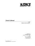
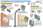
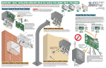
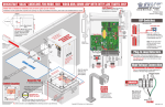
QUICKSTART “BASIC” GUIDELINES FOR MODEL 115 VAC 6003 - FOR A GATE UP TO 10 FEET, 300LBS AND “OPENING TO THE INSIDE”
Mounting System and Adjusting Open/Close Position
Gate Hinge Pivot Point
40.5” Fixed Position
H
I
Limitt
ens
or.
J Circuit board power
wn
ove
it
im
3L
cov
er.
Do not install the actuator arm in
fully extended (Bottomed out)
position. This will damage the arm
(See Actuator Arm and Control
Box Mounting manual for more
information).
A
Control Box
DO NOT cycle operator before limit sensors
and DIP-switches have been adjusted,
damage could occur to gate and operator.
Please refer to the Wiring/Owner’s manual.
Top
Battery Plug
Coaxial Cable Antenna Kit
P/N 1514-073 (Sold separately)
1
2
3
4
5
6
7
G
J
Power Conduit
board until power is needed to test the
actuator arm.
AC Power Switch
4302
2 3 4
5
Actuator
Cable
Brown
SINGLE/PRIMARY 1.
2. Blue
Actuator Cable
3. Orange
4. Red
Circuit Board
5. Yellow
Connection
Copyright 2013 DoorKing, Inc. All rights reserved.
6
6. Green
7. Green/White
#8 - #11 Shadow Loop Output
7 8 9 10 11 12 13 14 15 16 17 18 19 20
Loop
Jumper
Mounting
Hole
F
RED
Loops Conduit
1
G
E Do not connect the battery to the circuit
RED 24V
Coaxial
Cable
Antenna
Coaxial Cable Antenna
(Not Supplied)
Battery Connection
CAUTION
BLK 115V WHT
Bottom
E
Relay must be set
to N.O. for shadow
loop.
H
Actuator
Cable
Receiver Manual (available from
www.dkaccess.com) for more information on
radio receivers and antenna installation. See
reverse side for wiring.
B
D
Middle
D Not included - Refer to a specific Radio
I
DO NOT connect the
Primary operator to
this connection.
Connect Secondary
operator ONLY.
Securely mount control box
near the actuator arm with
appropriate hardware
(not supplied).
Actuator arm and brackets MUST be level!
A support
bar must be
installed the
entire length
of the gate
to support
the pickets.
Radio Receiver
Cut Off Excess Bracket
115 VAC Connection
BOX MUST BE
DANGER CONTROL
PROPERLY GROUNDED!!
F HIGH VOLTAGE!
White - Neutral
Black - 115 VAC Hot
Green - Chassis Ground
Alarm
Reset
C
Loop Wires
Chassis
Ground
Tip: Never run low voltage
rated wire insulation in the
same conduit as high voltage
rated wire insulation. Keep
them in separate conduits.
High Voltage
rem
Dual Channel
Reverse and Shadow
Plug-In Loop Detector
Single Channel Exit
Plug-In Loop Detector
manual and Loop Information Manual
(available free from www.dkaccess.com) for
more information.
12 V
3 Amp/Hr
Battery
wn
lo D
4S
9409
N
C
to
C
N
O
ws
C Not included - Refer to the Wiring/Owner’s
To #8
C 9410
1. ON - Relay for Dual Plug-In Shadow Loop
2. OFF - Relay for Dual Plug-In Shadow Loop
3. OFF
Note: Please refer to the
4. OFF
Wiring/Owner’s manual for
SW 2
more information.
Plug-In Loop Detectors
To #11
N.O.
cre
must be on to adjust
limit sensors, LEDs
will light.
Open to
the Inside
Position
Mounting Holes
Com
it s
RESET BUTTON: Resets circuit board.
Low Voltage
lim
KEY SWITCH BUTTON: Cycles operator when pressed.
4 Open Input
5 Open Input
ust
Com
Relay
24V
4s
OPEN
ew
90°
ON
scr
adj
lo D
6S
CLOSE
7”
1. Direction Primary operator opens.
2. OFF
B
3. OFF
4. ON
Auto-Close Timer
5. ON - Shadow Loop
1 23
6. OFF
Adjust 1 to 23 sec.
7. OFF
SW 1 8. OFF
1 2 3 4
Un
Li
7”
Cut Off Excess Bracket
A
ON
Closed Position
1 2 3 4 5 6 7 8
5
t
mi
to
Typical Settings for Single Operator with Plug-In Loops
See reverse side.
Rear Bracket
(Adjustable, See Manual)
Slow Down
nut
Circuit Board Settings
Manual Key Release
Limit Sensors
sen
120 Glasgow Avenue
Inglewood, California 90301
U.S.A.
Front Bracket
Note: This illustration shows
NO gate hinge inset. If gate
hinge is inset on wall, see
“Rear Bracket Configurations
for Different Gate Hinge Insets”
in the Actuator Arm and Control
Box Mounting manual.
Loo
Rear Bracket Pivot Point
12 V
3 Amp/Hr
Battery
Front Bracket Pivot Point
Model 115 VAC 6003 is intended for installation only on swing gates used for vehicles.
Pedestrians must be supplied with a separate access opening. For safety and installation instructions, please refer to the
6003 Actuator Arm and Control Box Mounting manual and the 115 VAC Control Box Wiring/Owner’s manual.
Tip: It is recommended
that a surge suppressor
be installed on the high
voltage power lines.
Note: To turn-off ALL power to the operator, the AC
power switch must be turned off and the battery
plug must be disconnected from the circuit board.
Wire Size
14 AWG
12 AWG
Distance
Up to 200 ft 115 VAC Input
Power Wire
Beyond 200 ft
6003-066-L-1-13
QUICKSTART “BASIC” GUIDELINES FOR MODEL 115 VAC 6003 - DIP-SWITCH AND WIRING REFERENCE
Model 115 VAC 6003 is intended for installation only on swing gates used for vehicles.
24 VAC Input
24 VAC Input
Low Voltage Common
Alarm Reset
Not Used
12 Volt Battery Input
Not Used
DC Lock Power Common
Dry Relay Contact
Dry Relay Contact
Low Voltage Common
Low Voltage Common
Full Open
7 8
Standard Reverse
Low Voltage Common
9 10 11 12 13 14 15 16 17 18 19 20
6
Overlapping
Gates
OFF Both operators start at the same time.
ON Secondary operator opens 1-2 seconds before primary operator. Vice-versa when closing.
7
Single
Dual
Input Power
OFF Switch must be OFF for single operator.
ON Switch must be ON when (dual) operators are used.
OFF Switch MUST be in the OFF position.
Function
ON
1 2 3 4
1 and 2
Relay
Operation
3
Maglock Used
No Maglock
Spare
Com
Power
5
Reverse
Not Used
ON (normal) Terminal #4 is normal open command.
OFF
ON
OFF (normal)
ON
Relay
Auto-Close
Timer
3-Wire
RF Receiver
Do not power any control
devices from the circuit
board other than low
voltage devices.
Auto-close timer is OFF. Manual input required to close gate.
Auto-close timer is ON. Adjustable from 1-23 seconds.
Terminal #8 is a standard Reverse input.
On setting is NOT used.
Power
Relay
Relay Com
Power Com
4-Wire
RF Receiver
Note: After a DIP-switch
setting is changed, press the
reset button for new settings
to take effect.
Setting
1-OFF
1-OFF
1-ON
1-ON
2-OFF
2-ON
2-OFF
2-ON
ON
OFF
OFF
Description
Relay activates when gate is fully open.
Relay activates when gate is not closed.
Relay activates when gate is opening and open. Shadow loop setting if used.
Relay activates when gate is opening and closing.
1 second delay to disengage maglock.
Leave in the OFF position if a maglock is NOT used.
Leave in the OFF position.
Note: Circuit board provides
24 VDC to power maglock.
Contact rating is 1 amp
maximum at 24 Volts.
Safety Opening Device
Com (Dry contact)
N.O.
Connect optional control devices to
the main terminal. Use 18 AWG wire
for all low voltage wiring, maximum
distance 3000 feet. Use a low voltage
surge suppressor, (DoorKing P/N
1878-010) if low voltage wire runs
exceed 1000 feet. All control device
inputs to the terminal must be
NORMALLY OPEN.
Com
N.O.
Keypad
(Dry contact)
Com
Deluxe
115 VAC
Control
Box
Three 115 VAC Convenience Outlets
Power safety and opening devices
that require 115 VAC power.
Controls must be far
enough from the gate so
that the user is prevented
from coming in contact
with the gate while
operating the controls.
ON
4
OFF Terminal #4 is output from plug-in exit loop detector installed in EXIT loop port.
SW 2
Switch 3 ON
1 2 3 4 5 6 7 8
Exit Loop Port
Output
Open Input
N.C.
ON
3
Same opening directions as illustrated above for the primary operator type.
• Switch 2 will be the SAME setting as switch 1.
Note: SW1, switch 7 MUST also be ON when using a secondary operator.
Reversing input on
Terminal #8
functions ONLY
while the gate is at
the FULL OPEN
position or during the CLOSING cycle. It
MUST NOT be used as an input for a
secondary entrapment protection device
during the OPENING gate cycle. Refer to
Secondary Entrapment Protection Wiring
in the Wiring/Owner’s manual.
Com
1 2 3 4
ON
1 2 3 4 5 6 7 8
2
4
6
ON setting.
Opens counter-clockwise.
SW 2 DIP-Switches
SW 2
5
U.S.A.
Magnetic Lock
Opening
Direction of
SECONDARY
Operator
Switch
2 3 4
120 Glasgow Avenue
Inglewood, California 90301
OFF setting.
Opens clockwise.
ON setting.
Opens clockwise.
8
1
Full Open
OFF setting.
Opens counter-clockwise.
1
SW 1
Description
Opening Direction of PRIMARY Operator
24 VDC - 250 ma max.
Setting
Full Open
Switch Function
Low Voltage Common
SW 1 DIP-Switches
24 VDC Maglock Power
Main Terminal
Pedestrians must be supplied with a separate access opening. For safety and installation instructions, please refer to the
6003 Actuator Arm and Control Box Mounting manual and the 115 VAC Control Box Wiring/Owner’s manual.
SW 1
N.O.
Key Switch
(Dry contact)
Switch 3
MUST be
ON.
Com
N.O.
Telephone Entry
Note: Must use a
separate power source.