1
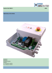
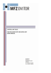
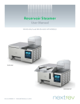
USER MANUAL ACS-50 CONTROL PANEL ALBANY DOOR SYSTEMS 975-A Old Norcross Road Lawrenceville, GA 30045 1080 Maritime Drive Port Washington, WI 53074 262-268-9885 TEL 262-268-9895 FAX www.albanydoors.com Table of Contents ACS-50 CONTROLLER SPECIFICATIONS ...................................................................................................................................... 3 ACS-50 ELECTRICAL PRACTICES .................................................................................................................................................. 4 ACS50 Control Panel Interior (Single speed) .................................................................................................. 5 ACS-50 Motherboard Layout .......................................................................................................................... 6 ACS50 Control Panel Interior (Two speed) ..................................................................................................... 6 WIRING TO PANEL ....................................................................................................................................... 9 Incoming Power ............................................................................................................................................................................ 9 Voltage Selector Jumper (J2) ........................................................................................................................................................ 9 Wiring of the Motherboard ........................................................................................................................................................... 9 ACS-50 SETTINGS AND ELECTRICAL STARTUP ...................................................................................................................... 11 CPU Card Switch Settings ............................................................................................................................. 11 (SW2) Rotary Selector Switch for Closing Time ........................................................................................................................ 11 Table 2 – Sw2 Settings ................................................................................................................................... 11 Setting of Opening and Closing Functions .................................................................................................... 12 Table 4 – Led Indication of the CPU Card .................................................................................................... 13 Electrical Start Up .......................................................................................................................................... 14 Micro switch ............................................................................................................................................................................... 14 Contact point ............................................................................................................................................................................... 14 Limit Switch Coarse Adjustment ................................................................................................................................................ 15 Turning on the Door Controller .................................................................................................................................................. 15 Phase Check ................................................................................................................................................................................ 15 Hold-to-Run-Function ................................................................................................................................................................. 16 Input Device Check ..................................................................................................................................................................... 16 Limit Switch Fine Adjustment .................................................................................................................................................... 16 The Crash-Function..................................................................................................................................................................... 16 Runtime Monitoring .................................................................................................................................................................... 17 Safety Circuit Limit Box (GFA Drives Only) ............................................................................................................................. 17 Photocell Cut-off (GFA Drives Only) ......................................................................................................................................... 17 Inertia Brake Wiring (if Equipped) ............................................................................................................................................. 17 Pressure Switch Adjustment (if Equipped) ................................................................................................................................. 18 TROUBLESHOOTING ...................................................................................................................................................................... 19 WD501-BF002 = ACS50 1 Speed - Bonfiglioi Motor & Limit Diagram – Models 570 & 670 ................................................ 20 WD501-BF003 = ACS50 2 Speed - Bonfiglioli Motor & Limit Diagram - Models 570 & 670................................................ 21 WD501-BF007 = ACS50 1 Speed - Bonfiglioli Motor & Limit Diagram - Model 392 ............................................................ 22 WD501-BF006 = ACS50 1 Speed - Bonfiglioli Motor & Limit Diagram Model 230 .............................................................. 23 WD501-BF005 = ACS50 2 Speed - Bonfiglioli Motor & Limit Diagram Model 230.............................................................. 24 WD501-BF008 = ACS50 Bonfiglioi Motor & Limit Diagram – Model 392.............................................................................. 25 WD501-0V000 = ACS50 Ovitor Motor & Limit Diagram ......................................................................................................... 26 WD501-GF002 – ACS50 GFA Operator Wiring 1-Speed .......................................................................................................... 27 WD501-GF001 - ACS50 GFA Operator Wiring 2-Speed .......................................................................................................... 28 WD502-0000-1 = Door Control Wiring Electric Edge and Crash Sensor .................................................................................. 29 WD503-PC000 = Reversing Photocell Wiring ........................................................................................................................... 30 WD504-0000 = ACS50 Actuator Options .................................................................................................................................. 31 WD502-0000A = Interlocking two ACS50 Units ....................................................................................................................... 32 ACS50 Contactless Safety Edge Wiring (if equipped) ............................................................................................................... 33 Blanking Light Curtain Photocell Wiring ................................................................................................................................... 34 CONTROL PANEL REPLACEMENT PARTS ................................................................................................................................. 35 Part # 6410T0008 -2- Revision 4.01 ACS-50 CONTROLLER SPECIFICATIONS ACS50 SPECIFICATIONS VALUES 208-240 VAC 3-PHASE SUPPLY VOLTAGE: 440-480 VAC 3-PHASE 575-600 VAC 3-PHASE MAXIMUM CURRENT: 10 AMPS TEMPERATURE, MINIMUM: -4 F, -20 C TEMPERATURE, MAXIMUM: +131 F, +55 C NEMA 1, 3R, 4, 12 AND 13 ENCLOSURE PROTECTION CLASS: NOTE: 4X STAINLESS OPTIONAL DIMENSIONS: 11.8“W X 15.75“H X 8.25“ DEEP WEIGHT: 24 LBS ALBANY DOOR SYSTEMS RAPID ROLL DRIVE UNITS 1-speed brake motor Output power Voltage Current NEMA Protection 1.5 208-240 440-480 550-600 4.9 2.5 1.85 12 / 13 Thermal Switch 2-speed brake motor 1.5/1 208-240 440-480 550-600 4.9/3.6 2.5/1.8 1.87/1.36 12 / 13 Thermal Switch Unit HP VAC A WARNING DO NOT INSTALL, OPERATE, OR SERVICE THIS PRODUCT UNLESS YOU HAVE READ AND UNDERSTAND THE SAFETY PRACTICES, WARNINGS, INSTALLATION, AND MAINTENANCE INSTRUCTIONS CONTAINED IN THIS MANUAL. Part # 6410T0008 -3- Revision 4.01 ACS-50 ELECTRICAL PRACTICES WARNING THE ACS-50 CONTROL BOX CONTAINS HIGH VOLTAGE. QUALIFIED ELECTRICAL PERSONNEL SHOULD PERFORM THE FOLLOWING PROCEDURES ONLY. WIRING AND CONTROL PANEL MOUNTING (ANCHORING) MUST MEET ALL LOCAL, STATE, FEDERAL, INTERNATIONAL, OR OTHER GOVERNMENT AGENCY CODES. FAILURE TO DO SO COULD RESULT IN SERIOUS INJURY OR DEATH. THE CONTROL PANEL SHOULD BE MOUNTED APPROXIMATELY 48 INCHES OFF OF THE FINISHED FLOOR FOR EASE OF TROUBLESHOOTING AND SERVICE. WIRING FOR POWER, (MOTOR AND BRAKE) SHOULD BE A MINIMMUM OF 14AWG. FOR CONTROL WIRING, SHOULD BE A MINIMUM OF 18 AWG. 1. NOTE: REFERENCE FIGURE BELOW AS A GUIDE FOR MAKING THESE WIRE CONNECTIONS TO THE UNIQUE WAGO STYLE TERMINALS. 1. Insert a mini screwdriver in the operating slot, located on the top of the terminal, up to the stop. 2. The screwdriver blade holds the clamping spring open automatically so that the conductor can be introduced into the clamping unit 3. Insert the wire into the block. 4. Withdraw the screwdriver – the conductor is automatically clamped. WARNING A SEPERATE FUSED DISCONNECT IS REQUIRED FOR PROTECTION OF THE DRIVE AND CONTROL SYSTEM. THIS DISCONNECT IS TO BE SUPPLIED BY OTHERS. THE DISCONNECT PROVIDED ON THE CONTROL BOX IS NONFUSED. ALL CONDUIT PENATRATIONS MUST BE IN THE BOTTOM OF THE CONTROL PANEL ENCLOSURE. TOP PENATRATION OF THE ENCLOSURE CAN VOID WARRANTY. Part # 6410T0008 -4- Revision 4.01 ACS50 Control Panel Interior (Single speed) Part # 6410T0008 -5- Revision 4.01 ACS-50 Motherboard Layout The following refers to the layout of the motherboard inside the ACS 50 control box: Control Fuses, FU1 – FU6 CPU Card Slot Motherboard Voltage Selector Jumper, J2 Cycle Counter Contactor ”KM1” and ”KM2” Brake Rectifier (230VAC) Contactor ”KM3” 2- Speed Only” Panel Disconnect, Nonfused Motor lead wiring ACS50 Control Panel Interior (Two speed) Part # 6410T0008 -6- Revision 4.01 Figure 7 – Single Speed Motherboard Part # 6410T0008 -7- Revision 4.01 Figure 8 – Two Speed Motherboard Part # 6410T0008 -8- Revision 4.01 WIRING TO PANEL Incoming Power Three Phase power coming from a FUSED DISCONNECT is wired into T1, T2, and T3. Located on the disconnect. Voltage Selector Jumper (J2) Check J2 for the proper incoming voltage level. This jumper wire comes from the motherboard and is terminated on a terminal below the control transformer. This is factory preset and should not normally need to be changed. Pneumatic safety edge (if equipped) The pneumatic edge pressure switch is wired to a set of terminals 7A and 8A for rapid roll doors, which is mounted on the din rail right below the motherboard. (Required for door operation.) Re-Coil-Away and Rapid Roll 392 doors do not have this resistor in the control panel but located on the end of the safety edge Electric Edge Connection (if equipped) Connect the electric edge directly to terminals 7 and 8 (edge is not adjustable). To test, (turn power on) bump the rubber safety edge with your hand observe LED 6 (see Figure 5 for location), it should flash on briefly. The edge is now operational. Ground Bar All grounds coming into the panel should be terminated on the ground bar at the bottom of the panel. Wiring of the Motherboard The motherboard component layout and numbering is shown in Figure 7 for ONE-speed motors, and in Figure 8 for TWO-speed motors. Also refer to wiring diagrams on pages 18-30 for the following: Ovitor motors Figure 9, for Bonfiglioli motors Figure 10, for GFA drives. Table 1 shows the motherboard terminal listing and descriptions. For any additional external devices consult factory for wiring details. Figure 9 Figure 10 Part # 6410T0008 -9- Figure 11 Revision 4.01 Table 1 - Mother Board Terminal Wiring Terminal T3, N, N U,V,W U2,V2,W2 1&2 1A & 2A 3&4 3A & 4A 5&6 5A & 6A 7&8 7A & 8A 9 & 10 12 & 13 20 21 22 23 20A 21A 22A 23A 33 33A 34 34A 35 & 36 37 & 38 45 & 46 53 & 54 55 & 56 63 & 64 70 & 71 74 75 76 77 78 79 80 80A 81 81A 82 83 Notice NOT USED Inertia Brake if applicable Electric Edge option Pneumatic Edge option See WD503-PC000 for details See WD503-PC000 for details 84 Output, 24VDC Negative Output, 24VDC Positive Optional Motor Thermal switch contact (jumper to 36 if not used) Hoist or Brake disengagement (jumper to 38 if not used) Crash sensor (jumper to 46 if not used) Reserve, input Reserve, output Output, 24V AC BRAKE 180VDC output (not used on Ovitor motors) Dry contact contact “Door opened” (Common) Dry contact contact “Door opened” (N.O.) Dry contact contact “Door opened” (N.C.) Dry contact contact “Door closed” (Common) Dry contact contact “Door closed” (N.O.) Dry contact contact “Door closed” (N.C.) Optional Optional Optional Optional Optional Optional Optional Optional Optional Optional Optional Optional Dry contact contact “ Alarm, Door not ready to work” (N.O.) Dry contact contact “ Alarm, Door not ready to work” (Common) Optional Dry contact contact “ Alarm, Door not ready to work” (N.C.) N.O. = Normally Open circuit Part # 6410T0008 Description Mains output (NOT USED) Motor (Single Speed) (Din rail mounted on Version 2 board) Motor (Two Speed) (Din rail mounted on Version 2 board) Stop1 N.C. Stop2 N.C. Open N.O. Open N.O. Close N.O. Close N.O. Electric Safety edge, resistor principle, 8,2kOhm Pneumatic Safety Edge With Seriesed 8.2kOhm resistor Limit switch “Door opened” Limit switch “Door closed” Safety photocell 1 – power (DC-) Safety photocell 1 - power (DC+) Switched for self test Safety photocell 1 - power (DC+) Safety photocell 1 - Signal Safety photocell 2 – power (DC-) Safety photocell 2 - power (DC+) Switched for self test Safety photocell 2 - power (DC+) Safety photocell 2 - Signal Dry contact contact “Warning light” Dry contact contact “Warning light” N.C. = Normally Closed Circuit -10- Revision 4.01 ACS-50 SETTINGS AND ELECTRICAL STARTUP CPU Card Switch Settings (SW2) Rotary Selector Switch for Closing Time Automatic closing can be set from 1-60 seconds. The potentiometer (SW2) is located on the CPU-card; see Figure 12 and Table 2 for settings. Note: the SW2 in combination with the SW1 setting also has an effect on the operation sequence as shown in Table 4. Refer to Figure 12 for switch location. Table 2 – Sw2 Settings SW2 Position 0 1 2 3 4 5 6 7 8 9 A B C D E F Close Time ↕ 1 2 3 4 5 7 10 13 16 19 22 25 30 45 60 Note: When SW2 is set in position 0, the door will not automatically close. You need to give a new impulse of an OPEN device to close the door or impulse a CLOSE device. Jumper J1- Bottom Edge Selector The Jumper1 is located on the CPU-card as shown on Figure 12. This is factory set as shown below. 3 2 JUMPER Top of Board 1 J1 LED 1 LED 17 LED 26 SW2 EPROM Top of Board SW1 FIGURE 12 – CPU Card Part # 6410T0008 -11- Revision 4.01 Setting of Opening and Closing Functions In the table below, SW1.1 means switch position 1 on SW1 dipswitch. Likewise, SW1.2 means switch position 2 on SW1 dipswitch. Refer to Figure 12 for switch location. The greyed out section below shows the factory settings. You need to change these settings for your particular needs. Table 3– Setting of Opening and Closing Functions SW 1.1 SW 1.2 SW 2 Terminal 3(A),4(A) (Remote Activation) Terminal 5(A),6(A) (Remote Activation) Panel Buttons UP DOWN ON ON ON ON ON ON OFF OFF 0 1-F 0 1-F UP – DOWN UP – AUTO. + CAP UP UP – AUTO. UP – DOWN UP – DOWN UP – DOWN UP – DOWN UP UP- AUTO UP UP - AUTO DOWN DOWN DOWN DOWN OFF ON 0 UP + CAP DOWN UP - CAP DOWN OFF ON 1-F UP – AUTO. UP – AUTO. UP - AUTO DOWN OFF OFF OFF OFF 0 1-F UP UP – AUTO. DOWN DOWN UP UP - AUTO DOWN DOWN SW1.3 OFF = Does not require reset after safety edge trip. ON = Requires reset after safety edge trip. Must reset by hold to close by pressing down button and fully closing the door LEGEND for Table 3: AUTO. = Automatic closing from open position. Delay before close time is adjustable from1 sec to 60 seconds depending on SW2 setting as specified in TABLE 2. The UP button (or 3(A) & 4(A) remote) will reset the timer, and prevent the door from closing until released. The shaded row in the above table is the most commonly used settings for auto close function. CAP = Automatic “CLOSE AFTER PASSING” the door photocell. The door will remain open until the photocell beam is broken and re-established. If the door is in UP – AUTO + CAP mode, it will then close after a fixed 2-second delay (not adjustable) once the photos have been passed through and cleared. If the door is in UP –CAP mode, the door will then close after the UP (or 3(A) & 4(A) remote) or DOWN (or 5(A) & 6(A) remote) buttons are pressed UP – DOWN = When the door is open, an impulse of the UP button (or 3(A) & 4(A) remote) will close the door when in this mode. Part # 6410T0008 -12- Revision 4.01 Table 4 – Led Indication of the CPU Card LED # LED COLOR Wiring Terminals / Notes Function Status Open Status (MID) Status Closed 1 Yellow 3(A) & 4(A) 5(A) & 6(A) Signal Open OFF OFF OFF 2 Green 1 & 2 or 1A & 2A (Jump if not used) Signal Stop / Inertia Brake if Applicable ON ON ON 3 Yellow Signal Close OFF OFF OFF 4 Yellow 9 & 10 Limit switch “Door opened” ON OFF OFF 5 Yellow 12 & 13 Limit switch “Door closed” OFF OFF ON 6 Red 7a and 8a if pneumatic 7 and 8 if Electric (8.2K resistor to bypass into 7 & 8) Safety edge (on if activated) OFF OFF OFF 7 Green 20,21,22,23 (Jump 21 to 23 to bypass for testing only) See schematics for color code wiring Safety photocell 1 (off if beam is blocked or not aligned) ON ON ON 8 Green 35 & 36 (Jump if not used) Thermal contact ON ON ON 9 Green 37 & 38 (Jump if not used) Manual lever or Hoist disengagement ON ON ON 10 Yellow Ribbon cable Open button of the control box OFF OFF OFF 11 Green 45 & 46 (Jump if not used) Crash sensor ON ON ON Optional input --- OFF OFF On while door is closing Test of “close”-relay OFF OFF OFF 12 Red 13 Yellow 14 Yellow Ribbon Cable Close button of the control box OFF OFF OFF 15 Green 20A, 21A, 22A, 23A (Jump 21A - 23A to bypass for testing only) See schematics for color code wiring Safety photocell 2 (Off if beam is blocked or not aligned) ON ON ON 16 Yellow Not Used OFF OFF OFF 17 Yellow Relay “Open” OFF OFF OFF 18 Yellow Relay “Close” OFF OFF OFF 19 Yellow 70 & 71 – (Measure 180 VDC output) Brake OFF OFF OFF 20 Red Red illuminated stop button on the face of the control box (FLASHES FOR 3 SECONDS ON STARTUP) Solid if error. Verify LED’s on this chart OFF OFF OFF 21 Yellow Traffic light or Warning light / horn (On during open & 2 sec’s priot to & closing) OFF OFF OFF 22 Green 80 & 81 / 80A & 81A 10A 250VAC DRY CONTACT ONLY 82 & 83 N.O. / 83 & 84 N.C. 10A 250VAC DRY CONTACT ONLY Alarm / Fault Indicator ON ON ON 23 Yellow Optional output OFF OFF 24 Green Test of the photocell ON ON ON 25 Red Check photo wiring for bad connections Error indicator – Photocell has a short circuit OFF OFF OFF Dip switch SW 1.3 is set to on Error indicator – Safety edge requires reset (see SW1.3) OFF OFF OFF 26 Red Part # 6410T0008 (Tab on open contactor will move when door is opening) (Tab on close contactor will move when door is closing) -13- Revision 4.01 Electrical Start Up WARNING First you must determine what type of limit box you have. Consult Figures below to determine this. Figure 14 is the STROMAG limits box. Figure 15 is the TEMEC limit box. Figure 16 is the GFA limit Box. Open Limit Cam Adjustment Screw Close Limit Cam Open Limit Cam Closed Limit Cam Microswitches Figure 14 Figure 15 Microswitches Allen Wrench Gearbox Micro switch Bottom Limit Contact point Top Limit Adjustment point Cam Lock Part # 6410T0008 Figure 16 -14- Figure 17 Revision 4.01 Limit Switch Coarse Adjustment Refer to the Electrical drawing WD501-0V000 for wiring of the Temec/Ovitor limit switch. For the wiring of the Stromag Limits refer to Electrical drawing WD501-BF000. For GFA LIMIT Boxes refer to electrical drawing WD501-GF02. Warning Rotation of the open limit cam in the wrong direction or incorrect phasing may cause the bottom beam assembly to jam into the top roll. 1. Remove the limit switch box cover, and manually bring the door down to one foot below the full open position. Observe the rotation direction of the limit cams while the door moves. The limit switch box for the TEMEC/Ovitor (figure 15) is located on the gearbox; The Temec style limit uses the threaded brass bolt to finely adjust limit switch cams. NOTE: A SMALL CHANGE IN THE CAM POSITION WILL RESULT IN A LARGE CHANGE IN THE MOVEMENT OF THE DOOR. The Stromag limits (figure 14) module is attached to the Bonfiglioli Motors via the chain drive. The Stromag sytle limits use a screwdriver to rotate the adjustment screw The GFA (figures 16 & 17) limit switch box is located behind the motor and under the gearbox.) Using the included Allen wrench loosen and then rotate the open limit cam (figure 17 &18) until it makes contact with its associated micro switch. Then lock the cam with the Allen wrench. The RED open and close safety limit cams are pre-adjusted and are piggybacked to the Green open and close limit cams. If this safety point needs to be corrected this can be adjusted using the fine adjustment screw to advance or retard the position of the red cam in relation to the position of the green cam. The red cams are so the door stops safely if the direction of the rotation is reversed or the open limit switch fails. During normal operation the RED cams should never make contact with their switch but should be close enough to activate if the primary limits fail. 2. Rotate the open limit cam until it makes contact with its associated micro switch. 3. Move the door to one foot from the fully closed position. Observe the rotation direction of the limit cams while the door moves. 4. Rotate the closed limit cam until it makes contact with its associated micro switch. Turning on the Door Controller When the door controller has been wired correctly, the switch SW1 and SW2 settings are complete, and the coarse limit adjustment is complete, the power may be turned on. Upon power up, the door controller will do an initial test for 3 seconds to see whether the software and the RAM are working properly. During this 3-second test, the controller will not respond to any open or close signals and the door will not open or close and the red illuminated button on the control box will flash. If the test detects a failure, the red illuminated button will illuminate constantly, the alarm relay will be activated, and the door controller becomes locked. When the initial-test is over and no fault has been detected, the controller is ready to work . Phase Check Note: in this step it is assumed that the door is still closed from the coarse limit-setting step. Part # 6410T0008 -15- Revision 4.01 1. Be prepared to press the STOP button. (Stop on the front panel is a momentary stop only! Door can be activated by motion detector, floor loop, or any activation device) It is highly recommended that ALL automatic or remote activations be disconnected during the startup of the door. This will eliminate unwanted activations which can create startup issues. 2. Push the open impulse button. The door should open at full speed. 2.1. If the door starts to close, stop the door immediately by pressing the STOP button and swap the position of the incoming power wires to T1 & T2. 2.2. If the door opens, make sure it stops at the open limit. If it goes beyond the open limit as set in the coarse limit-setting step, stop the door immediately and troubleshoot the limit wiring and/or setting. 3. Repeat this check until the door opens to top limit and stops at the close limit. Hold-to-Run-Function If the safety edge or safety photocells (safety circuits) have any fault(s), the door will no longer close automatically, and the system will go into Hold-to-run mode. An illuminated Stop button on the control panel indicates hold-to-run mode. If the Hold-to-run-mode is activated, it is not possible to close the door via external activators or signals. It is necessary to push the “Close” button to reset the door controller. Every other signal to reset will not have any effect. Reset of the Hold-to-run mode will occur when both safety circuits are working again and pushing the CLOSE button on the control panel successfully closes the door. Input Device Check Press the STOP button to prevent the door from moving. Operate each applicable input device as listed in Table 3 to verify device wiring. Refer to Table 4 to understand the proper light indication. When finished, restore the door from hold to run mode as described above. Limit Switch Fine Adjustment Refer to the limit switch appendix for details on the specific limit switch type used on your door. 1. Make sure the door can be actuated to open and close properly and that the door stops at the coarse limit settings. 2. Make small adjustments to the cams and cycle the door open and closed to observe changes in the limit settings. 3. Continue to finely adjust each cam until the desired door limits are attained. Once the door limits are adjusted correctly and the door is operating satisfactorily. Replace the limit switch box cover. On the Temec style and GFA style of limit box ensure the limit cams are tightened and locked. The Crash-Function (For doors with breakaway and impact detection only) if the door has been impacted and the bottom beam has been knocked out of the side-frame, the door stops immediately and the red illuminated push button is lit. Part # 6410T0008 -16- Revision 4.01 Once the door has been impacted, to restore full function of the door, press the ▲ up arrow button. The door then will go to full open and reset itself close. Runtime Monitoring The controller has an internal timer to measure the door run time when opening or closing. The timer expires after the door runs continuously for 20 seconds (some doors have a 40 second EPROM). If this occurs, the door will immediately stop and the red button on the panel will be lit solid. To reset this condition, disconnect main power (off). Verify that the door is not binding or you have a motor/gearbox problem. After this check, then reapply power. Safety Circuit Limit Box (GFA Drives Only) The terminals 21 to 28 on the limit switch figure 18 are reserved for the safety circuit. An interruption of the safety circuit causes the control voltage to be interrupted. Electrical operation is no longer possible when this occurs. Photocell Cut-off (GFA Drives Only) The limit switch (S6) must be adjusted to bypass the photocells when the door is approximately 8 inches off the ground. This allows the bottom loop on the bottom beam assembly to clear the photocell and not cause the door to reverse. Not used with Light Curtains. S5 AUX S6 Photocell Cutoff Figure 18 Inertia Brake Wiring (if Equipped) (Re-Coil-Away Doors ONLY with chain drive and without counter balance springs) The inertia brake needs to wired in order for the door to operate. Refer to electrical drawings for wiring points. If the red indicator is extended from the housing the electrical contact will be in an open position and thus preventing the door from operating. Part # 6410T0008 -17- Revision 4.01 Pressure Switch Adjustment (if Equipped) Bump the rubber safety edge with your hand observe LED 6 (see Figure 9 for location), it should flash on briefly. If the LED does not flash, adjust the switch. The pressure switch is located on the bottom beam see Figure 19. Remove the cover of the pressure switch enclosure. Rotate the white plastic screw on the pressure switch clockwise with a small screwdriver until the LED 6 turns on. Then rotate the screw counter-clockwise until LED 6 turns off, and then rotate an additional ¼ turn. Test the safety edge and observe LED 6 (it should turn on momentarily whenever pressure is applied to safety edge). (Note: LED 26 turns off if edge fails pulse test when in pneumatic mode = not used.) Figure 19 Part # 6410T0008 -18- Revision 4.01 TROUBLESHOOTING TABLE 5- Controller Faults Red Lamp + LED 20 (ON PANEL STOP BUTTON) Alarm (OUTPUT TERMS 82-84) Error Description Indication Flash ON Power on test First 3 seconds after Power on Flash ON Manual lever, Handcrank, activated LED 9 = OFF ON ON Safety edge error LED 6 = ON ON ON Photocell error LED 25 = ON OFF OFF Photocell blocked LED 7 = OFF (Photocell 1) LED 15 = OFF (Photocell 2) ON ON Thermal contact activated LED 8 = OFF; Door controller is locked ON ON Safety edge was triggered: SW1-3 = ON LED 26 = ON ON ON EPROM Check sum error Door controller is locked; No “power on test” indication ON ON RAM Error Door controller is locked; No “power on test” indication If LED’s 7, 8, 9, or 15 is not on when the system is powered up it will go into a locked condition. Reset power and see which light is not lit and then check that item to get that light to be on. If you have all the proper LED except for LED’s 2 & 4 you need to check the wiring and or jumpers at terminals 1& 2 or 1A & 2A. No lights on the CPU CARD Part # 6410T0008 Terminal 33 and 34 should have 24VDC availible if not check fuses. Also check terminal 63 and 64 for 24VAC -19- Revision 4.01 A company of Albany lnternational Corp. WD501-BF002 = ACS50 1 Speed - Bonfiglioi Motor & Limit Diagram – Models 570 & 670 Part # 6410T0008 -20- Revision 4.01 A company of Albany lnternational Corp. WD501-BF003 = ACS50 2 Speed - Bonfiglioli Motor & Limit Diagram - Models 570 & 670 High Part # 6410T0008 -21- Low Revision 4.01 A company of Albany lnternational Corp. WD501-BF007 = ACS50 1 Speed - Bonfiglioli Motor & Limit Diagram - Model 392 Part # 6410T0008 -22- Revision 4.01 A company of Albany lnternational Corp. WD501-BF006 = ACS50 1 Speed - Bonfiglioli Motor & Limit Diagram Model 230 Part # 6410T0008 -23- Revision 4.01 A company of Albany lnternational Corp. WD501-BF005 = ACS50 2 Speed - Bonfiglioli Motor & Limit Diagram Model 230 High Part # 6410T0008 -24- Low Revision 4.01 A company of Albany lnternational Corp. WD501-BF008 = ACS50 Bonfiglioi Motor & Limit Diagram – Model 392 Part # 6410T0008 -25- Revision 4.01 A company of Albany lnternational Corp. WD501-0V000 = ACS50 Ovitor Motor & Limit Diagram Part # 6410T0008 -26- Revision 4.01 A company of Albany lnternational Corp. WD501-GF002 – ACS50 GFA Operator Wiring 1-Speed Part # 6410T0008 -27- Revision 4.01 A company of Albany lnternational Corp. WD501-GF001 - ACS50 GFA Operator Wiring 2-Speed High Part # 6410T0008 -28- Low Revision 4.01 A company of Albany lnternational Corp. WD502-0000-1 = Door Control Wiring Electric Edge and Crash Sensor Part # 6410T0008 -29- Revision 4.01 A company of Albany lnternational Corp. WD503-PC000 = Reversing Photocell Wiring Part # 6410T0008 -30- Revision 4.01 A company of Albany lnternational Corp. WD504-0000 = ACS50 Actuator Options Part # 6410T0008 -31- Revision 4.01 A company of Albany lnternational Corp. WD502-0000A = Interlocking two ACS50 Units Part # 6410T0008 -32- Revision 4.01 ACS50 Contactless Safety Edge Wiring (if equipped) Part # 6410T0008 -33- Revision 4.01 Blanking Light Curtain Photocell Wiring Part # 6410T0008 -34- Revision 4.01 CONTROL PANEL REPLACEMENT PARTS PART # 4903T0001 4903T0002 4903T0003 4903T0004 4906T0016 4908T0011 4909T0001 4911T0012 4911T0013 4920T0001 4920T0002 4920T0009 980072-4019 980072-7504 980072-9500 980072-9501 980082-7505 980082-7506 4904.415 PART DESCRIPTION Control Panel, ACS50, 220/480/600v, 1-Speed CUL Control Panel, ACS50, 220/480/600V, 2-Speed CUL Control Panel, ACS50, Stainless Steel 220/480/600V, 1-Speed Control Panel, ACS50, Stainless Steel 220/480/600V, 2-Speed ACS50 Steel Enclosure With Prepunched Holes Fuse Holder, ACS50 Rectifier, ACS50, 220 Volt, CUL Terminal Block, 6mm, 35mm Din Rail Terminal Block, End Stop, 35mm Din Rail Motherboard, ACS50, CUL, One Speed (Does not include CPU card or rectifier) Motherboard, ACS50, CUL, Two Speed (Does not include CPU card or rectifier) CPU CARD, ACS50 w/ 4916T0002 40 Sec Run Time Eprom Resistor, 8.2K, 1/8w Pigtail for Pnuematic edge Disconnect, Rotary Switch, Rod And Handle Included FUSE, ACS50, 250V1A, F2 & F3 position FUSE, ACS50, 250V 0.5A F1 & F6 position Push Button, Red, ACS50 Push Button, Amber, Open/Close, ACS50 Loop Detector, 24 VDC/AC, FEIG Albany Door Systems Customer Support [email protected] Aftermarket Parts 770-338-5000 Tel 770-338-5034 Fax Technical Support 262-268-9885 Tel 262-268-9895 Fax Part # 6410T0008 -35- Revision 4.01 NOTES: ACS-50 Control Panel Manual DOCUMENT TITLE DOCUMENT NUMBER 980076-0000 ISSUE DATE September 2009 DOOR MODEL(S) ALL ELECTRONIC FILE ACS50 Control V4.01.doc ASSEMBLY CONTROLS Part # 6410T0008 REPLACES -36- ACS50 v4.doc Revision 4.01