1
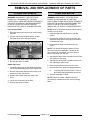
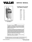
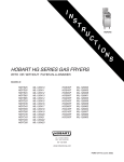
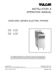
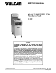
SERVICE MANUAL
SUPPLEMENT
KLEENSCREEN SERIES ELECTRIC
FRYER BATTERY
MODEL
2ERD40F SHOWN
ML
ERD40F
126905
ERD50F
126906
ERD225F
126907
ERD85F
126908
ERC40F
126909
ERC50F
126910
ERC225F
126911
ERC85F
126912
This Service Manual Supplement should be used
in addition to F24577 "FLOOR MODEL ELECTRIC
FRYERS" for Service Information related to the
Fryer and F24599 "MOBILE FILTERS" for Service
Information related to the pump.
- NOTICE This Manual is prepared for the use of trained Vulcan Service
Technicians and should not be used by those not properly
qualified. If you have attended a Vulcan Service School for this
product, you may be qualified to perform all the procedures
described in this manual.
This manual is not intended to be all encompassing. If you have
not attended a Vulcan Service School for this product, you should
read, in its entirety, the repair procedure you wish to perform to
determine if you have the necessary tools, instruments and skills
required to perform the procedure. Procedures for which you do
not have the necessary tools, instruments and skills should be
performed by a trained Vulcan Service Technician.
Reproduction or other use of this Manual, without the express
written consent of Vulcan, is prohibited.
A product of VULCAN-HART
LOUISVILLE, KY 40201-0696
F24696 (May 2001)
ER SERIES FRYER SERVICE MANUAL SUPPLEMENT
TABLE OF CONTENTS
GENERAL . . . . . . . . . . . . . . . . . . . . . . . . . . . . . . . . . . . . . . . . . . . . . . . . . . . . . . . . . . . . . . . . . . . . . . . . . . . . .
Introduction . . . . . . . . . . . . . . . . . . . . . . . . . . . . . . . . . . . . . . . . . . . . . . . . . . . . . . . . . . . . . . . . . . . . . . . .
Description . . . . . . . . . . . . . . . . . . . . . . . . . . . . . . . . . . . . . . . . . . . . . . . . . . . . . . . . . . . . . . . . . . . . .
Model Designations . . . . . . . . . . . . . . . . . . . . . . . . . . . . . . . . . . . . . . . . . . . . . . . . . . . . . . . . . . . . . .
Kleenscreen Filtering System . . . . . . . . . . . . . . . . . . . . . . . . . . . . . . . . . . . . . . . . . . . . . . . . . . . . . . .
Information Sources . . . . . . . . . . . . . . . . . . . . . . . . . . . . . . . . . . . . . . . . . . . . . . . . . . . . . . . . . . . . . .
Installation . . . . . . . . . . . . . . . . . . . . . . . . . . . . . . . . . . . . . . . . . . . . . . . . . . . . . . . . . . . . . . . . . . . . . . . . .
Operation . . . . . . . . . . . . . . . . . . . . . . . . . . . . . . . . . . . . . . . . . . . . . . . . . . . . . . . . . . . . . . . . . . . . . . . . . .
Cleaning . . . . . . . . . . . . . . . . . . . . . . . . . . . . . . . . . . . . . . . . . . . . . . . . . . . . . . . . . . . . . . . . . . . . . . . . . .
Maintenance . . . . . . . . . . . . . . . . . . . . . . . . . . . . . . . . . . . . . . . . . . . . . . . . . . . . . . . . . . . . . . . . . . . . . . .
Specifications . . . . . . . . . . . . . . . . . . . . . . . . . . . . . . . . . . . . . . . . . . . . . . . . . . . . . . . . . . . . . . . . . . . . . .
Electrical . . . . . . . . . . . . . . . . . . . . . . . . . . . . . . . . . . . . . . . . . . . . . . . . . . . . . . . . . . . . . . . . . . . . . .
3
3
3
3
4
4
4
4
4
4
5
5
REMOVAL AND REPLACEMENT OF PARTS . . . . . . . . . . . . . . . . . . . . . . . . . . . . . . . . . . . . . . . . . . . . . . . . .
Covers and Panels . . . . . . . . . . . . . . . . . . . . . . . . . . . . . . . . . . . . . . . . . . . . . . . . . . . . . . . . . . . . . . . . . . .
Pump and Motor . . . . . . . . . . . . . . . . . . . . . . . . . . . . . . . . . . . . . . . . . . . . . . . . . . . . . . . . . . . . . . . . . . . .
Filter Valve and Discard Valve Switches . . . . . . . . . . . . . . . . . . . . . . . . . . . . . . . . . . . . . . . . . . . . . . . . . .
Heater Contactors . . . . . . . . . . . . . . . . . . . . . . . . . . . . . . . . . . . . . . . . . . . . . . . . . . . . . . . . . . . . . . . . . . .
6
6
6
7
7
SERVICE PROCEDURES AND ADJUSTMENTS . . . . . . . . . . . . . . . . . . . . . . . . . . . . . . . . . . . . . . . . . . . . . . . 8
Computer Control Board Diagnostics . . . . . . . . . . . . . . . . . . . . . . . . . . . . . . . . . . . . . . . . . . . . . . . . . . . . . 8
ELECTRICAL OPERATION . . . . . . . . . . . . . . . . . . . . . . . . . . . . . . . . . . . . . . . . . . . . . . . . . . . . . . . . . . . . . . . 9
Sequence of Operation . . . . . . . . . . . . . . . . . . . . . . . . . . . . . . . . . . . . . . . . . . . . . . . . . . . . . . . . . . . . . . . 9
Solid State Fryer Control, Full Vat . . . . . . . . . . . . . . . . . . . . . . . . . . . . . . . . . . . . . . . . . . . . . . . . . . . 9
Computer Control, Full Vat . . . . . . . . . . . . . . . . . . . . . . . . . . . . . . . . . . . . . . . . . . . . . . . . . . . . . . . . 11
Kleenscreen Filtering System . . . . . . . . . . . . . . . . . . . . . . . . . . . . . . . . . . . . . . . . . . . . . . . . . . . . . . 12
Discard of Used Oil . . . . . . . . . . . . . . . . . . . . . . . . . . . . . . . . . . . . . . . . . . . . . . . . . . . . . . . . . . . . . 13
Component Function . . . . . . . . . . . . . . . . . . . . . . . . . . . . . . . . . . . . . . . . . . . . . . . . . . . . . . . . . . . . . . . . 14
Component Location . . . . . . . . . . . . . . . . . . . . . . . . . . . . . . . . . . . . . . . . . . . . . . . . . . . . . . . . . . . . . . . . 15
Schematic Diagrams . . . . . . . . . . . . . . . . . . . . . . . . . . . . . . . . . . . . . . . . . . . . . . . . . . . . . . . . . . . . . . . . 16
Solid State Control and Kleenscreen Filter, Full Vat . . . . . . . . . . . . . . . . . . . . . . . . . . . . . . . . . . . . . 16
Computer Control, Full Vat . . . . . . . . . . . . . . . . . . . . . . . . . . . . . . . . . . . . . . . . . . . . . . . . . . . . . . . . 18
Computer Control, Split Vat . . . . . . . . . . . . . . . . . . . . . . . . . . . . . . . . . . . . . . . . . . . . . . . . . . . . . . . 19
Kleenscreen Filtering System, Computer Control . . . . . . . . . . . . . . . . . . . . . . . . . . . . . . . . . . . . . . . 20
Heater Circuit, Solid State Controls, Full Vat . . . . . . . . . . . . . . . . . . . . . . . . . . . . . . . . . . . . . . . . . . 21
Heater Circuit, Solid State Controls, Split Vat . . . . . . . . . . . . . . . . . . . . . . . . . . . . . . . . . . . . . . . . . . 22
Basket Lift Circuit, Solid State Controls . . . . . . . . . . . . . . . . . . . . . . . . . . . . . . . . . . . . . . . . . . . . . . 23
Wiring Diagrams . . . . . . . . . . . . . . . . . . . . . . . . . . . . . . . . . . . . . . . . . . . . . . . . . . . . . . . . . . . . . . . . . . . 24
Kleenscreen Filtering System . . . . . . . . . . . . . . . . . . . . . . . . . . . . . . . . . . . . . . . . . . . . . . . . . . . . . . 24
Wiring Diagram Index . . . . . . . . . . . . . . . . . . . . . . . . . . . . . . . . . . . . . . . . . . . . . . . . . . . . . . . . . . . . 25
TROUBLESHOOTING . . . . . . . . . . . . . . . . . . . . . . . . . . . . . . . . . . . . . . . . . . . . . . . . . . . . . . . . . . . . . . . . . .
Solid State Control . . . . . . . . . . . . . . . . . . . . . . . . . . . . . . . . . . . . . . . . . . . . . . . . . . . . . . . . . . . . . . . . . .
Computer Control . . . . . . . . . . . . . . . . . . . . . . . . . . . . . . . . . . . . . . . . . . . . . . . . . . . . . . . . . . . . . . . . . .
Computer Control Harness Pin-Outs Chart . . . . . . . . . . . . . . . . . . . . . . . . . . . . . . . . . . . . . . . . . . . . . . . .
Kleenscreen Filtering System . . . . . . . . . . . . . . . . . . . . . . . . . . . . . . . . . . . . . . . . . . . . . . . . . . . . . . . . . .
50
50
51
52
53
CONDENSED SPARE PARTS LIST . . . . . . . . . . . . . . . . . . . . . . . . . . . . . . . . . . . . . . . . . . . . . . . . . . . . . . . . 56
© VULCAN 2001
F24696 (May 2001)
Page 2 of 56
ER SERIES FRYER SERVICE MANUAL SUPPLEMENT - GENERAL
GENERAL
INTRODUCTION
Description
Model Designations
This Service Manual Supplement covers specific
service information only related to the Vulcan
Kleenscreen filter models listed on the front cover.
The fryer battery utilizes many of the same controls
and components as the Vulcan ERD series (solid
state control) and ERC series (computer control)
fryers.
Kleenscreen fryer batteries are available in a
minimum of two and a maximum of six fryer
sections. The fryer size of each section is identical.
An ERO series Frymate (dump station) can also be
included as one or more of the sections.
Models, Features and Options
FEATURES
OPTIONS
FRYER
WIDTH
(INCHES)
FRYING
COMPOUND
PER FRYER
(POUNDS)
VAT
TYPE
CONTROL
TYPE
2ERD40F 1
31
40
Full
2ERD50F 1
31
50
2ERD225F 1
31
2ERD85F 2
2ERC40F
1
2ERC50F
1
MODEL
BASKET LIFTS
AUTOMATIC
TIMERS
(MIN)
Solid State
Single or Dual
7.5 or 15
Full
Solid State
Single or Dual
7.5 or 15
50
(25 each vat)
Split
Solid State
Single
(each vat)
7.5 or 15
42
85
Full
Solid State
Single or Dual
7.5 or 15
31
40
Full
Computer
Single or Dual
7.5 or 15
31
50
Full
Computer
Single or Dual
7.5 or 15
2ERC225F 1
31
50
(25 each vat)
Split
Computer
Single
(each vat)
7.5 or 15
2ERC85F 2
42
85
Full
Computer
Single or Dual
7.5 or 15
ER015 (Frymate)
15 1/2
ER021 (Frymate)
21
NOTES:
1. For each additional fryer section, add 15 1/2 inches to the width.
2. For each additional fryer section, add 21 inches to the width.
Page 3 of 56
F24696 (May 2001)
ER SERIES FRYER SERVICE MANUAL SUPPLEMENT - GENERAL
Kleenscreen Filtering System
The new "Kleenscreen" filtering system has been integrated into the ER Series fryer battery. The filter is housed
in a pull-out drawer assembly at the base of the fryer. The filtering components in the drawer include a stainless
steel filter tank, crumb-catch basket and fine mesh screen. With the filter drawer closed, a self-seating return oil
line provides the path to return the filtered oil to the fry tank.
This system is designed to provide a thorough and easy method for filtering fryer oil.
Some of the benefits include:
•
Self-contained system eliminating the use of external filter equipment.
•
Paperless filtering system.
•
Easy to clean and low maintenance.
Information Sources
Refer to the appropriate manual below for related information.
ER SERIES
ELECTRIC
FRYERS
PUMP
INFORMATION
KLEEN
SCREEN
Service
F24577
F24599
-
Parts
F31007
-
-
Installation and
Operation
F30981
-
-
-
-
F31150
MANUAL
Filtration System
User’s Guide
F24696
Use the Service information found in this
Service Manual Supplement. The
Supplement covers additional Service
Information specific to the Kleenscreen
fryer and filtering system.
INSTALLATION
Refer to the Installation and Operation Manual for specific installation instructions.
OPERATION
Refer to the Installation and Operation Manual for specific operating instructions.
CLEANING
Refer to the Installation and Operation Manual for specific cleaning instructions.
MAINTENANCE
Refer to the Installation and Operation Manual for specific maintenance instructions.
F24696 (May 2001)
Page 4 of 56
ER SERIES FRYER SERVICE MANUAL SUPPLEMENT - GENERAL
SPECIFICATIONS
Electrical
Separate electrical connections are required for each section of the battery.
•
208VAC, 240VAC or 480VAC (3 phase, 60HZ) to power the heating elements.
•
On 208VAC and 240VAC models, step down transformer(s) provide power for the fryer controls, basket lift(s)
if installed, and Kleenscreen filtering controls.
•
On 480VAC models, a 120VAC connection is required for each fryer section.
•
All models require a separate 120VAC connection for the pump motor.
NOTE: Pump motor for Kleenscreen filtering system draws 5.0 amps.
AMPS - EACH FRYER SECTION
(3 PHASE/ 60HZ) 1
MODEL
ERD40F
ERD50F
ERD225F
ERD85F
ERC40F
ERC50F
ERC225F
ERC85F
NOTES:
KW
PER FRYER
SECTION 3
RECOMMENDED
CIRCUIT
PROTECTION 2
PER LINE
208V
240V
480V
208V
240V
480V
14
39
34
17
50
45
25
17
47
41
20
60
50
30
14
39
34
17
50
45
25
17
47
41
20
60
50
30
21
58
51
25
80
70
35
14
39
34
17
50
45
25
17
47
41
20
60
50
30
21
58
51
25
80
70
35
24
67
58
29
90
80
40
14
39
34
17
50
45
25
17
47
41
20
60
50
30
14
39
34
17
50
45
25
17
47
41
20
60
50
30
21
58
51
25
80
70
35
14
39
34
17
50
45
25
17
47
41
20
60
50
30
21
58
51
25
80
70
35
24
67
58
29
90
80
40
1. Amperage values in the table are nominal. Tolerance is
+5/-10%.
2. Complied in accordance with National Electric Code,
ANSI/NFPA 70, latest edition.
3. 14kw is standard on all fryers except 85 lb. models which
are 24kw.
Page 5 of 56
F24696 (May 2001)
ER SERIES FRYER SERVICE MANUAL SUPPLEMENT - REMOVAL AND REPLACEMENT OF PARTS
REMOVAL AND REPLACEMENT OF PARTS
COVERS AND PANELS
PUMP AND MOTOR
WARNING: DISCONNECT THE ELECTRICAL
POWER TO THE MACHINE AT THE MAIN
CIRCUIT BOX. THERE ARE SEVERAL SEPARATE
CIRCUITS. BE SURE ALL ARE DISCONNECTED.
PLACE A TAG ON THE CIRCUIT BOX(ES)
INDICATING THE CIRCUIT IS BEING SERVICED.
WARNING: DISCONNECT THE ELECTRICAL
POWER TO THE MACHINE AT THE MAIN
CIRCUIT BOX. THERE ARE SEVERAL SEPARATE
CIRCUITS. BE SURE ALL ARE DISCONNECTED.
PLACE A TAG ON THE CIRCUIT BOX(ES)
INDICATING THE CIRCUIT IS BEING SERVICED.
Front Control Panel
NOTE: Refer to component location picture 6100 for
location of pump motor.
1. Open the cabinet door to the fryer section being
serviced.
2. Remove the screws along the bottom lip and
along the top of the of the control panel.
1. Open the right side cabinet door of the filter
section.
2. Pull the filter drawer out, remove the filter tank
assembly and push the tank support arms back
underneath the fryer.
3. Disconnect the electrical connection to the
motor.
NOTE: The remaining steps are written for front
removal of the pump assembly. If access to the
back of the fryer is available, it may be easier to
remove the pump from the rear.
4. Separate the swivel hose connection on the right
side (intake) of the pump.
3. Work the panel loose at each end and lift off.
5. Separate the swivel hose connection on the left
side (discharge) of the pump.
4. Reverse procedure to install.
Basket lift Covers
6. Remove the mounting bolts from the motor.
1. Loosen bolt at the top of each basket lift hanger
and lift the basket hangers from the support rod.
7. Remove the motor, pump and piping assembly.
A.
2. Remove the screws that secure the lower cover
at the rear of the fryer section.
3. Remove the screws along each side of the
cover.
4. Lift the cover and place to the side.
8. Reverse procedure to install.
NOTE: Ensure the rubber vibration pad or the
grommets are installed under the motor mounting
plate.
5. Reverse procedure to install.
F24696 (May 2001)
If replacing the pump and motor, remove
the existing piping assemblies and reuse.
Page 6 of 56
ER SERIES FRYER SERVICE MANUAL SUPPLEMENT - REMOVAL AND REPLACEMENT OF PARTS
FILTER VALVE AND DISCARD
VALVE SWITCHES
HEATER CONTACTORS
WARNING: DISCONNECT THE ELECTRICAL
POWER TO THE MACHINE AT THE MAIN
CIRCUIT BOX. THERE ARE SEVERAL SEPARATE
CIRCUITS. BE SURE ALL ARE DISCONNECTED.
PLACE A TAG ON THE CIRCUIT BOX(ES)
INDICATING THE CIRCUIT IS BEING SERVICED.
WARNING: DISCONNECT THE ELECTRICAL
POWER TO THE MACHINE AT THE MAIN
CIRCUIT BOX. THERE ARE SEVERAL SEPARATE
CIRCUITS. BE SURE ALL ARE DISCONNECTED.
PLACE A TAG ON THE CIRCUIT BOX(ES)
INDICATING THE CIRCUIT IS BEING SERVICED.
1. Open the cabinet door to the fryer section being
serviced.
1. Remove the front control panel as outlined under
"FRONT CONTROL PANEL" in "COVERS AND
PANELS".
2. Disconnect lead wire connector from the
appropriate switch.
2. Remove the combination mounting and cover
panel from the control area.
3. Remove switch mounting screws.
4. Reverse procedure to install.
NOTE: Switch mounting is a fixed location and has
no provision for adjustment.
3. Contactors are now accessible.
NOTE: Refer to "COMPONENT LOCATION".
4. Reverse procedure to install.
Page 7 of 56
F24696 (May 2001)
ER SERIES FRYER SERVICE MANUAL SUPPLEMENT- SERVICE PROCEDURES AND ADJUSTMENTS
SERVICE PROCEDURES AND ADJUSTMENTS
COMPUTER CONTROL BOARD
DIAGNOSTICS
The computer control is used on other equipment and is capable of displaying many different prompts.
Therefore, some prompts not applicable may display when a problem occurs in the wiring harness. Since the
computer is looking for either 24 VAC or 24 VAC ground on particular pins, an open connection can cause a nonapplicable prompt to appear. Refer to "COMPUTER CONTROL HARNESS PIN-OUTS CHART" under
"TROUBLESHOOTING".
Diagnostics are divided into two areas, "OPERATION" and "SERVICE". Operation mode is the standard mode of
fryer operation. Service mode is intended to give the service technician more information regarding the nature of
a problem encountered. In either mode the fryer operates normally until an error occurs.
If an error occurs, the information displayed will be different. The chart below shows what is displayed for both
"OPERATION" and "SERVICE" modes.
The "SERVICE" mode can only be entered while an error is occurring. To enter the service mode, press and hold
the product 3 and 4 keys and turn the power switch ON. To exit, turn the power switch OFF.
The following displays/computer responses will be given for the noted conditions.
CONDITION
OPERATION MODE
DIAGNOSTICS
DISPLAY
SERVICE MODE
DIAGNOSTICS
DISPLAY
COMPUTER RESPONSE
No input on
pins
3, 4, 5, or 6
IGN FAILURE
IGN FAILURE on
left side or right side
for split vat only
HEAT OFF
LO TEMP XXXF
HEAT OFF
Temperature is below the lowest operational set point. Refer
to "COMPUTER CONTROL" under
"TROUBLESHOOTING".
HI TEMP XXX(F
HIGH TEMP DISPLAYED
Output at pin 15 and/or 16 (split vat) should already be OFF
unless there is a problem with computer. Vat temperature is
410°F or higher which is well above the highest operational
set point. Refer to "COMPUTER CONTROL" under
"TROUBLESHOOTING".
OFF
OFF DISPLAYED
Mechanical high limit is OPEN (435°F), heat OFF and input is
removed from pin 1 and/or pin 2 which indicates to the
computer --- VAT TURNED OFF.
Low
Temperature
(lack of heat)
High
Temperature
Alarm
High
Temperature
(high limit)
LOW TEMP
HIGH TEMP
OFF
Tilt Switch
OPEN
OFF
OFF
OFF DISPLAYED
Heaters raised or problem with the tilt switch. Heat is OFF
and input is removed from pin 1 and/or pin 2 which indicates
to the computer --- VAT TURNED OFF.
Drain Valve
Switch
(if installed)
DRAIN OPEN
DRAIN OPEN
DRAIN OPEN DISPLAYED, HEAT OFF
Input is removed from pin 10. Drain valve is OPEN or there is
a problem with switch.
Probe
Open or Short
CALL SERVICE
PROBE OPEN R or
L for split vat
PROBE SH R or L
for split vat
HEAT OFF
No input on
pin 11
CLOSE DOOR
CLOSE DOOR
HEAT OFF
Not passing
Self Check
CALL SERVICE
MICRO FAIL
System will operate in backup mode
F24696 (May 2001)
Page 8 of 56
ER SERIES FRYER SERVICE MANUAL SUPPLEMENT - ELECTRICAL OPERATION
Power up Diagnostics
On power up, the control will execute a self check. The failure of any of these tests will result in the message
“CALL SERVICE” or “MICRO FAIL” being displayed.
This prompt will flash at approximately a 1 hertz rate. While the prompt is displayed, the computer will not
function. If the failure is in the computer, the fryer will operate in backup mode.
When the fryer computer comes out of initialization and self check routines, it will either enter the heating mode
or the melt mode (if programmed) of operation.
For a split vat fryer, one vat can be OFF while the other is in operation. If this occurs, the side that is OFF will be
indicated by displaying the OFF prompt to the user. The message will be on the side of the display which
corresponds to the vat which is OFF.
System Tests
The system diagnostics menu is intended to give you the ability to test the basic parts of the computer. It can be
entered by pressing the 8 and 9 product keys simultaneously while turning on power to the fryer computer. The
message "SYSTEM TESTS" is displayed. In this mode you can select one of three tests.
With DISPLAY TEST displayed, press enter to begin a test, use the up and down arrows to rotate through the
screens. Press exit once to return to the test menu or twice to return to normal operation.
With KEYPAD TEST displayed, press enter to begin the test. The control will respond by displaying the name of
the key pressed. Press exit once to return to the test menu or twice to return to normal operation.
With VER xxx displayed, the release number is displayed as "VER XXX".
ELECTRICAL OPERATION
SEQUENCE OF OPERATION
3)
480VAC models - A separate
120VAC connection is used along
with step down transformer(s) to
provide power for the fryer controls,
basket lift(s) if installed, and the
Kleenscreen filtering controls.
4)
All models require a separate
120VAC connection for the pump
motor.
Solid State Fryer Control, Full Vat
Refer to schematic diagram TSP1567C for both the
"Fryer Controls" operation and the "Kleenscreen
Filtering system" operation.
FRY CYCLE - LIQUID FRYING OIL
NOTE: If using solid shortening, refer to "MELT
CYCLE - SOLID SHORTENING" in this section.
1.
Conditions.
A.
Fryer connected to correct supply voltage
(separate connections are required for
each section of the battery).
B.
24VAC transformer energized.
C.
Fryer properly grounded.
D.
Internal fryer circuit breakers ON.
NOTE: 208 and 240VAC models at 21 and 24
KW only.
1)
208, 240 or 480VAC - power for
heating elements.
E.
Power switch to the fryer section controls
in center NEUTRAL (starting) position.
2)
208 or 240VAC models - Step down
transformer(s) provide power for the
fryer controls, basket lift(s) if
installed, and the Kleenscreen
filtering controls.
F.
Tilt switch contacts CLOSED (N.O. - held
CLOSED with heating elements down).
G.
Second high limit thermostat CLOSED.
H.
Frying oil at the proper level in vat and
below 300°F.
I.
Fry/Melt switch in FRY position.
J.
Temperature control set to desired frying
temperature.
Page 9 of 56
F24696 (May 2001)
ER SERIES FRYER SERVICE MANUAL SUPPLEMENT - ELECTRICAL OPERATION
2.
Press power ON switch.
4.
A.
24VAC initially energizes relay coil R1
through the momentary ON power switch
contacts (N.O.).
B.
When switch is released, relay coil R1
remains energized through R1-2 "latching
circuit" contacts (N.O.) and the momentary
OFF power switch contacts (N.C.).
C.
D.
1)
R1-1 CLOSED.
2)
R1-2 CLOSED.
A.
1)
Power ON light (red).
2)
Power supplied to basket lift controls,
if installed.
3)
1CON and 3CON through tilt switch
and second high limit thermostat.
4)
Temperature control board at proper
terminal (2, 3 or 4) for supply voltage
and jumpered to terminal 5.
Temperature control board evaluates the
inputs from thermistor and set point
potentiometer then energizes the board
relays.
2)
The Control relay contacts (N.O.) at
terminal 5 CLOSE.
B.
1)
The first high limit light comes ON.
2)
2CON and 4CON are de-energized
and power is removed from the
heating elements.
3)
Output is removed from terminal 6
when oil temperature drops below set
point temperature and is returned to
terminal 7.
b.
2CON and 4CON are energized
and heating elements are
powered.
Trouble "light" and second high limit
"light" come ON.
MELT CYCLE - SOLID SHORTENING
1.
The first high limit relay contacts
(N.C.) at terminal 6 change state to
the normally OPEN position and
provide a path to the output at
terminal 7.
a.
If the second high limit OPENS
(435°F ±15) or the tilt switch operates,
1CON and 3CON are de-energized and
power is removed from the heating
elements and heating stops.
1)
NOTE: The first high limit "light" may
quickly flash once, until the High limit relay
is energized.
Conditions.
A.
Same as outlined in steps 1A thru 1G
under "FRY CYCLE - LIQUID FRYING
OIL".
B.
Solid shortening at the proper pounds in
vat and at room temperature.
C.
Fry/Melt switch in MELT position.
D.
Temperature Control set to desired frying
temperature.
2.
Same as outlined in steps 2 thru 2. C. 4) under
"FRY CYCLE - LIQUID FRYING OIL".
3.
Temperature control board evaluates the inputs
from thermistor then energizes the board
relays.
Heat light comes ON.
NOTE: Refer to "SCHEMATIC
TSP1569C" under "SCHEMATIC
DIAGRAMS".
A.
Oil reaches set point temperature.
A.
If oil reaches 410°F ±5, the temperature
control de-energizes "high limit relay" on
board, contacts revert back to the normally
CLOSED position and the output changes
to terminal 6.
Supply voltage energizes the following
components:
1)
3.
Temperature control cycles output to terminal 7
until power switch is turned OFF, heating
elements are raised or a high limit condition
occurs.
Melt cycle is initiated and the temperature
control functions as a percent ON/OFF
timer.
Temperature control de-energizes the
"control relay" on board, contacts at
terminal 5 OPEN and the output at
terminal 7 is removed.
The control relay contacts (N.O.) at
terminal 5, cycle the output at
terminal 7 to energize 2CON and
4CON and power the heating
elements.
1)
2CON and 4CON are de-energized
and power is removed from the
heating elements.
a.
Initial condition is OFF 45
seconds.
b.
2)
Heat light goes OFF.
Heat condition ON 2 seconds
(heat light ON).
F24696 (May 2001)
1)
Page 10 of 56
ER SERIES FRYER SERVICE MANUAL SUPPLEMENT - ELECTRICAL OPERATION
4)
NOTE: Refer to "SCHEMATIC
TSP1569C" under "SCHEMATIC
DIAGRAMS".
B.
4.
B.
Control cycles output at time intervals of
30 seconds OFF, then 2 seconds ON (heat
light ON).
Melt cycle is automatically over-ridden.
NOTE: The Fry/Melt switch should remain in
the "Melt" position.
B.
5.
1)
Power to pins 3, 4, 5, 6, 11, and 17
(control system main input) on
computer main harness.
2)
24 VAC ground to pins 9, 12, and 13
(control system main input GND).
NOTE: Pin 12 on the main harness is used to
indicate to the computer the type of fryer (full
or split vat) the computer is installed in. If the
fryer is a full vat, pin 12 is tied to 24 VAC
ground. If the fryer is a split vat, pin 12 is tied
to 24 VAC.
Control uses thermistor input to cycle the
output at terminal 7.
Shortening reaches set point temperature.
A.
Control removes output from pin 7.
1)
2)
6.
24VAC transformer 2T energized.
Shortening temperature reaches 135(F.
A.
All models require a separate
120VAC connection for the pump
motor.
2CON and 4CON are de-energized
and power is removed from the
heating elements.
C.
Fryer properly grounded.
D.
Internal fryer circuit breakers ON.
NOTE: 208 and 240VAC models at 21 and 24
KW only.
Heat light goes out.
Control cycles the output at terminal 7, on the
vat temperature.
E.
Power switch to the fryer section controls
in the OFF position.
Computer Control, Full Vat
F.
Refer to schematic diagram’s TSP1571C for "Fryer
Controls" operation and TSP1587 "Kleenscreen
Filtering system" operation.
Tilt switch contacts CLOSED (N.O. - held
CLOSED with heating elements down).
G.
Second high limit thermostat CLOSED.
H.
Frying oil at the proper level in vat and
below 300°F.
I.
Computer control is setup properly and
ready to use.
FRY CYCLE - LIQUID FRYING OIL
NOTE: If using solid shortening, the computer
control should be programmed to use the MELT
CYCLE. In the MELT CYCLE, the computer will
"cycle" the heaters ON/OFF in short intervals to
gradually heat and liquify the shortening until it
reaches a temperature of 135°F.The computer then
resumes normal operation as described under FRY
CYCLE.
1.
2.
Press power ON switch.
A.
12VAC transformer 1T energized.
1)
Conditions.
A.
Fryer connected to correct supply voltage
(separate connections are required for
each section of the battery).
1)
208, 240 or 480VAC - power for
heating elements.
2)
208 or 240VAC models - Step down
transformer(s) provide power for the
fryer controls, basket lift(s) if
installed, and the Kleenscreen
filtering controls.
3)
480VAC models - A separate
120VAC connection is used along
with step down transformer(s) to
provide power for the fryer controls,
basket lift(s) if installed, and the
Kleenscreen filtering controls.
Page 11 of 56
B.
Computer power supply board PS-1 is
energized and a (+) 12VDC signal is
sent to pin 23 on the computer main
harness.
Computer control powers ON, initializes
and performs a diagnostic self check.
NOTE: If the control passes self check, then
the outputs are energized and operation
sequence continues. If control does not pass
self test then CALL SERVICE or MICRO FAIL
will display. Refer to "COMPUTER CONTROL
BOARD DIAGNOSTICS" under "SERVICE
PROCEDURES AND ADJUSTMENTS".
1)
R1 control relay, 1CON and 3CON
will energize.
a.
R1 relay energized, NO contacts
CLOSE and supply power to pin
1 on computer main harness.
F24696 (May 2001)
ER SERIES FRYER SERVICE MANUAL SUPPLEMENT - ELECTRICAL OPERATION
2)
NOTE: Pins 1 and 2 on the main
harness are used to monitor the
power switch "status" of the vat(s).
Pin 1 is the power status input on a
full vat or right side split vat and pin 2
is the input for the left side split vat
only. These inputs tell the computer
which vat(s) are turned ON or OFF.
3.
A.
Computer control evaluates the input from
thermistor then activates the 24VAC
output from pin 15 and power is applied to
R2 control relay.
1)
R2 control relay is energized and the
N.O. contacts CLOSE.
a.
2CON and 4CON are energized
and heating elements are
powered.
NOTE: Pin 15 and 16 on the main
computer harness are the heat
outputs. Pin15 is the full vat or right
side split vat output and pin 16 is the
left side output on a split vat only.
4.
5.
NOTE: If the second high limit trips for the
left side split vat only, R3 and contactors 3
and 4 are de-energized. Power is removed
form the left side vat heating elements
only and heating stops. R3 contacts OPEN
and remove power from pin 2 ( left side
split vat only). The display will indicate
“OFF” for the left side vat.
Computer control evaluates input from
thermistor at pins 3 and 4 (full vat or right side
split vat).
NOTE: Pins 1 and 2 (left side split vat only) on
temperature probe harness.
NOTE: The filter valve handle and the discard valve
handle are connected to a mechanical valve and
switch assembly to route the flow of oil filtering
system and supply power to the pump motor.
Kleenscreen Filtering System
For Solid State Control, refer to schematic diagram
TSP1567C for both the "Fryer Controls" operation
and the "Kleenscreen Filtering system" operation.
For Computer Control, refer to schematic diagrams
TSP1571C for the "Fryer Controls" operation and
TSP1587C for the "Kleenscreen Filtering system"
operation.
1.
Conditions
A.
Fryer connected to correct supply voltage
(separate connections are required for
each section of the battery).
B.
Fryer properly grounded.
C.
Power switch to fryer section controls
turned OFF.
D.
Frying oil below 300°F.
E.
Filter drawer assembly installed properly.
F.
Filter power switch turned OFF.
G.
Filter valve handle (red) retracted.
Oil temperature reaches set temperature.
A.
Computer turns OFF heat output and
control relay R2 de-energizes.
B.
2CON and 4CON are de-energized and
power is removed from heating elements.
Computer cycles heat output on oil temperature
until power switch is turned OFF, heating
elements are raised or a high limit condition
occurs.
NOTE: Steps 5A and 5B discuss OPEN high limits.
For additional information on computer control error
messages, refer to "COMPUTER CONTROL
BOARD DIAGNOSTICS" under "SERVICE
PROCEDURES AND ADJUSTMENTS".
A.
B.
If the oil reaches 410(F ±5, the display will
indicate “HI TEMP” as an alarm to the
operator only.
If the second high limit (435(F ±15)
OPENS or the tilt switch operates, the
control relay R1 and contactors 1 thru 4
are de-energized.
1)
Power is removed form the heating
elements and heating stops.
F24696 (May 2001)
R1 contacts OPEN and remove
power from pin 1 (full vat or right side
split vat). The display will indicate
“OFF”.
1)
H.
Discard valve handle (white) retracted.
1)
2.
Filter valve switch N.O. contacts
OPEN.
Discard valve switch N.O. contacts
OPEN.
Set temperature control between 300°F
(minimum) and 350°F (maximum).
NOTE: Oil should not be filtered outside of this
temperature range. At lower temperatures the oil is
thicker which may increase filtering time and place a
greater load on the pump. At higher oil
temperatures, oil seal life is deceased.
3.
Page 12 of 56
Turn the power switch ON, to the fryer section
to be filtered.
ER SERIES FRYER SERVICE MANUAL SUPPLEMENT - ELECTRICAL OPERATION
A.
Allow oil to cycle at set temperature for
approximately 10 minutes.
Discard of used oil
1.
NOTE: If using solid shortening, once it has
melted, stir the oil to eliminate any sold
shortening in cold zone of the vat. Refer to
"MELT CYCLE - SOLID SHORTENING".
A.
4.
Turn the power switch OFF, to the fryer section
to be filtered.
5.
Open the manual drain valve to the fryer
section in need of filtering and drain the liquid
oil/shortening into filter tank.
NOTE: If using solid shortening, allow hot
shortening to stand in filter tank for approximately 6
minutes prior to filtering.
6.
Turn filter power switch ON.
A.
7.
Open the manual drain valve to the fryer
section in need of oil discarding and drain the
oil into the filter.
3.
Attach oil drain hose the male quick connect
fitting on the fryer.
4.
Turn filter power switch ON.
A.
Place drain hose discharge end into a used oil
holding tank.
6.
Extend discard handle.
A.
1)
Filter relay coil is energized and the
N.O. contacts CLOSE.
1)
a.
Filter relay coil is energized and the
N.O. contacts CLOSE.
B.
Power supplied to pump motor.
7.
Pump motor circulates oil through filter
until power is removed.
Filter valve switch N.O. contacts OPEN.
1)
Filter relay coil is de-energized and
the N.O. contacts OPEN.
a.
Power is removed from pump
motor.
10. Turn filter power switch OFF.
NOTE: If using solid shortening, when all filtered oil
is returned to the vat and filter power switch is OFF,
open the filter drawer approximately one inch. Allow
the remaining shortening in the line to drain into the
filter tank to prevent possible clogging after the
shortening cools and solidifies. Close the filter
drawer when complete.
Oil begins flowing through drain hose into
holding tank until power is removed.
Discard valve switch N.O. contacts OPEN.
1)
Filter relay coil is de-energized and
the N.O. contacts OPEN.
a.
8.
When all filtered oil is returned to the fryer,
retract the filter valve handle.
Power supplied to pump motor.
When all used oil is emptied from the fryer,
retract the discard valve handle.
A.
When the oil filtering process is completed,
close the manual drain valve to the fryer and
allow the vat to refill.
A.
Discard valve switch N.O. contacts
CLOSE.
Filter valve switch N.O. contacts CLOSE.
NOTE: No electrical switching occurs by closing the
manual drain valve unless the optional drain valve
switch is installed.
9.
Switch pilot light comes ON.
5.
Switch pilot light comes ON.
a.
B.
Same as outlined in steps 1 thru 4 under
“KLEENSCREEN FILTERING SYSTEM”.
2.
Extend Filter valve handle of the same fryer
section.
A.
8.
Conditions
Power is removed from pump
motor.
Close the manual drain valve to the fryer.
NOTE: No electrical switching occurs by closing the
manual drain valve unless the optional drain valve
switch is installed.
9.
Turn filter power switch OFF.
NOTE: If using solid shortening, when all filtered oil
is returned to the vat and filter power switch is OFF,
open the filter drawer approximately one inch. Allow
the remaining shortening in the line to drain into the
filter tank to prevent possible clogging after the
shortening cools and solidifies. Close the filter
drawer when complete.
Page 13 of 56
F24696 (May 2001)
ER SERIES FRYER SERVICE MANUAL SUPPLEMENT - ELECTRICAL OPERATION
COMPONENT FUNCTION
NOTE: For components not listed here, refer to the ER series service manual listed on the front cover and under
"INFORMATION SOURCES" in the "GENERAL" section.
Filter Power Switch . . . . . . . . .
Supplies 120VAC to pump motor when filter relay is energized.
Filter Relay . . . . . . . . . . . . . . . .
Supplies 120VAC to pump motor through filter relay contacts (N.O.) when
24VAC coil is energized. Filter power switch must be ON and the filter valve
switch or discard valve switch must be CLOSED (valve handle extended).
Transformer 2T . . . . . . . . . . . .
Supplies 24VAC to the oil filter control circuit and fryer power switch.
Transformer is energized when supply power is connected to fryer.
Transformer 1T . . . . . . . . . . . .
Supplies 12VAC to the computer power supply board. Transformer is
energized when fryer power switch is turned ON. Computer control models
only.
Pump Motor . . . . . . . . . . . . . . .
Operates the "pump" to circulate oil through the filtering system.
Filter Valve Switch . . . . . . . . . .
Energizes the filter relay coil to supply power to the pump motor through
filter relay contacts (N.O.) when switch is CLOSED (valve handle extended).
When oil filtering is complete, close the manual drain valve to the fryer and
allow the vat to refill. Retract the filter handle when all filtered oil is returned.
Discard Valve Switch . . . . . . .
Energizes the filter relay coil to supply power to the pump motor through
filter relay contacts (N.O.) when switch is CLOSED (valve handle extended).
This allows the oil to be discarded through the discard hose into a separate
container. When filter tank is empty, retract the handle to return the discard
switch to normal operating position.
Fryer Power Switch . . . . . . . . .
Energizes relay coil R1 and supplies power to fryer control circuit through
relay R1-1 contacts (N.O.). The switch positions are: momentary ON,
momentary OFF with a center NEUTRAL (starting) position. Solid state
controls only.
Circuit 1 on the switch is the normally CLOSED (N.C.) side. Press power
OFF to momentarily OPEN switch contacts and turn the fryer OFF.
Circuit 2 on the switch is the normally OPEN (N.O.) side. Press power ON to
momentarily CLOSE switch contacts and turn the fryer ON.
Relay R1 . . . . . . . . . . . . . . . . . .
Supplies power to fryer control circuit and basket lift circuit (if installed)
through relay R1-1 contacts (N.O.) when 24VAC coil is energized. The relay
remains energized through R1-2 contacts (N.C.) and fryer power switch
contacts until power switch is turned OFF. Full vat and split vat fryers, solid
state controls only.
Relay R2 . . . . . . . . . . . . . . . . . .
Supplies power to fryer control circuit and basket lift circuit (if installed)
through relay R2-1 contacts (N.O.) when 24VAC coil is energized. The relay
remains energized through R2-2 contacts (N.C.) and fryer power switch
contacts until power switch is turned OFF. Split vat fryers with solid state
controls only.
F24696 (May 2001)
Page 14 of 56
ER SERIES FRYER SERVICE MANUAL SUPPLEMENT - ELECTRICAL OPERATION
COMPONENT LOCATION
Page 15 of 56
F24696 (May 2001)
ER SERIES FRYER SERVICE MANUAL SUPPLEMENT - ELECTRICAL OPERATION
SCHEMATIC DIAGRAMS
Solid State Control and Kleenscreen Filter, Full Vat
F24696 (May 2001)
Page 16 of 56
ER SERIES FRYER SERVICE MANUAL SUPPLEMENT - ELECTRICAL OPERATION
Solid State Control and Kleenscreen Filter, Split Vat
Page 17 of 56
F24696 (May 2001)
ER SERIES FRYER SERVICE MANUAL SUPPLEMENT - ELECTRICAL OPERATION
Computer Control, Full Vat
F24696 (May 2001)
Page 18 of 56
ER SERIES FRYER SERVICE MANUAL SUPPLEMENT - ELECTRICAL OPERATION
Computer Control, Split Vat
Page 19 of 56
F24696 (May 2001)
ER SERIES FRYER SERVICE MANUAL SUPPLEMENT - ELECTRICAL OPERATION
Kleenscreen Filtering System, Computer Control
F24696 (May 2001)
Page 20 of 56
ER SERIES FRYER SERVICE MANUAL SUPPLEMENT - ELECTRICAL OPERATION
Heater Circuit, Solid State Controls, Full Vat
Page 21 of 56
F24696 (May 2001)
ER SERIES FRYER SERVICE MANUAL SUPPLEMENT - ELECTRICAL OPERATION
Heater Circuit, Solid State Controls, Split Vat
F24696 (May 2001)
Page 22 of 56
ER SERIES FRYER SERVICE MANUAL SUPPLEMENT - ELECTRICAL OPERATION
Basket Lift Circuit, Solid State Controls
Page 23 of 56
F24696 (May 2001)
ER SERIES FRYER SERVICE MANUAL SUPPLEMENT - ELECTRICAL OPERATION
WIRING DIAGRAMS
Kleenscreen Filtering System
F24696 (May 2001)
Page 24 of 56
ER SERIES FRYER SERVICE MANUAL SUPPLEMENT - ELECTRICAL OPERATION
Wiring Diagram Index
SOLID STATE CONTROL, KLEENSCREEN
Full-Vat, 208 & 240 Volt 24 & 21 KW . . . . . . . . . . . . . . . . . . . . . . . . . . . . . . . . . . . . . . . . . . . . 26 & 27
Full-Vat, 208 & 240 Volt 17 & 14 KW . . . . . . . . . . . . . . . . . . . . . . . . . . . . . . . . . . . . . . . . . . . . 28 & 29
Full-Vat, 480 Volt 24, 21, 17 & 14 KW . . . . . . . . . . . . . . . . . . . . . . . . . . . . . . . . . . . . . . . . . . . 30 & 31
Split-Vat, 208 & 240 Volt 17 & 14 KW . . . . . . . . . . . . . . . . . . . . . . . . . . . . . . . . . . . . . . . . . . . 32 & 33
Split-Vat, 208 & 240 Volt 21 KW . . . . . . . . . . . . . . . . . . . . . . . . . . . . . . . . . . . . . . . . . . . . . . . . 34 & 35
Split-Vat, 480 Volt 14, 17 & 21 KW . . . . . . . . . . . . . . . . . . . . . . . . . . . . . . . . . . . . . . . . . . . . . . 36 & 37
COMPUTER CONTROL, KLEENSCREEN
Full-Vat, 208 & 240 Volt 17 & 14 . . . . . . . . . . . . . . . . . . . . . . . . . . . . . . . . . . . . . . . . . . . . . . . 38 & 39
Full-Vat, 208 & 240 Volt 24 & 21 KW . . . . . . . . . . . . . . . . . . . . . . . . . . . . . . . . . . . . . . . . . . . . 40 & 41
Full-Vat, 480 Volt 24, 21, 17 & 14 KW . . . . . . . . . . . . . . . . . . . . . . . . . . . . . . . . . . . . . . . . . . . 42 & 43
Split-Vat, 208 & 240 Volt 17 & 14 KW . . . . . . . . . . . . . . . . . . . . . . . . . . . . . . . . . . . . . . . . . . . 44 & 45
Split-Vat, 208 & 240 Volt 21 KW . . . . . . . . . . . . . . . . . . . . . . . . . . . . . . . . . . . . . . . . . . . . . . . . 46 & 47
Split-Vat, 480 Volt 21, 17 & 14 KW . . . . . . . . . . . . . . . . . . . . . . . . . . . . . . . . . . . . . . . . . . . . . . 48 & 49
Page 25 of 56
F24696 (May 2001)
ER SERIES FRYER SERVICE MANUAL SUPPLEMENT - ELECTRICAL OPERATION
F24696 (May 2001)
Page 26 of 56
ER SERIES FRYER SERVICE MANUAL SUPPLEMENT - ELECTRICAL OPERATION
Page 27 of 56
F24696 (May 2001)
ER SERIES FRYER SERVICE MANUAL SUPPLEMENT - ELECTRICAL OPERATION
F24696 (May 2001)
Page 28 of 56
ER SERIES FRYER SERVICE MANUAL SUPPLEMENT - ELECTRICAL OPERATION
Page 29 of 56
F24696 (May 2001)
ER SERIES FRYER SERVICE MANUAL SUPPLEMENT - ELECTRICAL OPERATION
F24696 (May 2001)
Page 30 of 56
ER SERIES FRYER SERVICE MANUAL SUPPLEMENT - ELECTRICAL OPERATION
Page 31 of 56
F24696 (May 2001)
ER SERIES FRYER SERVICE MANUAL SUPPLEMENT - ELECTRICAL OPERATION
F24696 (May 2001)
Page 32 of 56
ER SERIES FRYER SERVICE MANUAL SUPPLEMENT - ELECTRICAL OPERATION
Page 33 of 56
F24696 (May 2001)
ER SERIES FRYER SERVICE MANUAL SUPPLEMENT - ELECTRICAL OPERATION
F24696 (May 2001)
Page 34 of 56
ER SERIES FRYER SERVICE MANUAL SUPPLEMENT - ELECTRICAL OPERATION
Page 35 of 56
F24696 (May 2001)
ER SERIES FRYER SERVICE MANUAL SUPPLEMENT - ELECTRICAL OPERATION
F24696 (May 2001)
Page 36 of 56
ER SERIES FRYER SERVICE MANUAL SUPPLEMENT - ELECTRICAL OPERATION
Page 37 of 56
F24696 (May 2001)
ER SERIES FRYER SERVICE MANUAL SUPPLEMENT - ELECTRICAL OPERATION
F24696 (May 2001)
Page 38 of 56
ER SERIES FRYER SERVICE MANUAL SUPPLEMENT - ELECTRICAL OPERATION
Page 39 of 56
F24696 (May 2001)
ER SERIES FRYER SERVICE MANUAL SUPPLEMENT - ELECTRICAL OPERATION
F24696 (May 2001)
Page 40 of 56
ER SERIES FRYER SERVICE MANUAL SUPPLEMENT - ELECTRICAL OPERATION
Page 41 of 56
F24696 (May 2001)
ER SERIES FRYER SERVICE MANUAL SUPPLEMENT - ELECTRICAL OPERATION
F24696 (May 2001)
Page 42 of 56
ER SERIES FRYER SERVICE MANUAL SUPPLEMENT - ELECTRICAL OPERATION
Page 43 of 56
F24696 (May 2001)
ER SERIES FRYER SERVICE MANUAL SUPPLEMENT - ELECTRICAL OPERATION
F24696 (May 2001)
Page 44 of 56
ER SERIES FRYER SERVICE MANUAL SUPPLEMENT - ELECTRICAL OPERATION
Page 45 of 56
F24696 (May 2001)
ER SERIES FRYER SERVICE MANUAL SUPPLEMENT - ELECTRICAL OPERATION
F24696 (May 2001)
Page 46 of 56
ER SERIES FRYER SERVICE MANUAL SUPPLEMENT - ELECTRICAL OPERATION
Page 47 of 56
F24696 (May 2001)
ER SERIES FRYER SERVICE MANUAL SUPPLEMENT - ELECTRICAL OPERATION
F24696 (May 2001)
Page 48 of 56
ER SERIES FRYER SERVICE MANUAL SUPPLEMENT - ELECTRICAL OPERATION
Page 49 of 56
F24696 (May 2001)
ER SERIES FRYER SERVICE MANUAL SUPPLEMENT - TROUBLESHOOTING
TROUBLESHOOTING
SOLID STATE CONTROL
SYMPTOM
Fryer does not heat.
POSSIBLE CAUSES
1.
2.
3.
4.
5.
6.
Power switch OFF or inoperative.
Main circuit breaker(s) OFF or the fryers internal circuit
breaker(s), if applicable, OFF.
Control circuit fuse 1FU or 2FU OPEN.
Transformer 2T inoperative.
Drain valve switch malfunction (if installed).
Malfunctioning heat control relay R1 (full vat or right side
split vat) or R2 on left side split vat only.
Ventilator OFF, power switch ON, power light
ON.
1.
2.
3.
Ventilator hood circuit breaker OPEN.
Interlock wiring OPEN.
Power switch inoperative.
No heating light, power light ON.
1.
2.
3.
4.
Temperature control set too low or not calibrated.
Heating light inoperative.
Contactor(s) malfunction.
Control board malfunction.
No heating light, power light ON, trouble light
and first and second high limit lights ON.
1.
2.
3.
4.
5.
Low oil.
First high limit inoperative (control board).
Second high limit OPEN or tilt switch OPEN or tilt switch
malfunction.
Contactor(s) malfunction.
Control board malfunction.
Excessive time to melt shortening
(more than 45 minutes).
1.
2.
3.
Melt cycle timing incorrect (control board).
Heating elements malfunctioning.
Supply power incorrect voltage.
Fryer shuts down on first high limit and first
high limit light ON.
1.
2.
3.
4.
Low oil.
Control not calibrated.
Contactor(s) malfunction.
Control board malfunction.
Fryer shuts down on second high limit, power
light ON, no first high limit light and second
high limit light ON.
1.
2.
3.
4.
5.
Low oil.
First high limit "light" inoperative.
Second high limit OPEN or tilt switch OPEN or tilt switch
malfunction.
Contactor(s) malfunction.
Control board malfunction.
Thermostat out of calibration by more than
25(F.
1.
2.
3.
Probe touching element.
Probe malfunction.
Control board malfunction.
Light(s) not ON when required.
1.
2.
Light inoperative.
Wiring problem.
F24696 (May 2001)
Page 50 of 56
ER SERIES FRYER SERVICE MANUAL SUPPLEMENT - TROUBLESHOOTING
COMPUTER CONTROL
NOTE: The computer control is also used in other equipment, therefore it is possible for unrelated error prompts
to appear if a problem occurs in the computer main harness plug.
SYMPTOM
POSSIBLE CAUSES
Fryer does not heat.
1.
2.
Power switch OFF or inoperative.
Main circuit breaker(s) OFF or the fryers internal circuit
breaker(s), if applicable, OFF.
3. Control circuit fuse 1FU or 2FU OPEN.
4. Drain valve switch malfunction (if installed).
5. Malfunctioning heat control relay R2 (full vat or right side
split vat) or R4 on left side split vat only.
6. Contactor(s) malfunctioning.
7. Computer power supply board or transformer 1T or 2T
inoperative.
8. Open pins 23 or 24 (12 VDC).
9. Open 24 VAC pin 1 (full vat or right side split vat) or pin 2
on left side split vat only.
10. Open pin 15 right heat output (full vat or right side split
vat), or pin 16 left heat output on left side split vat only.
11. Computer main harness wiring problem.
12. Malfunctioning computer control.
Fryer displays "HI TEMP" alarm message.
1.
2.
3.
Low oil.
Frying oil temperature above 410°F, heating elements
not turning OFF.
A. Malfunctioning heat control relay R2 (full vat or right
side split vat) or R4 on left side split vat only.
B. Contactor(s) malfunctioning.
Malfunctioning computer control.
A. Pin 15 right heat output (full vat or right side split
vat), or pin 16 left heat output on left side split vat
only, not turning OFF.
Fryer heats slowly.
1.
2.
Incoming voltage incorrect.
Heating element(s) malfunction.
Fryer displays "CALL SERVICE"
1.
2.
3.
Probe malfunction.
Failed self-check.
Malfunctioning computer control.
Fryer displays "IGN FAILURE"
1.
Pins 3, 4, 5 or 6 not connected to 24VAC.
Fryer displays "DRAIN OPEN"
1.
2.
3.
Drain "ball" valve left OPEN.
Pin 10 not connected to 24VAC.
Drain valve switch malfunction (if installed).
Fryer displays "OFF"
1.
Second high limit OPEN or tilt switch OPEN or tilt switch
malfunction.
Page 51 of 56
F24696 (May 2001)
ER SERIES FRYER SERVICE MANUAL SUPPLEMENT - TROUBLESHOOTING
COMPUTER CONTROL
HARNESS PIN-OUTS CHART
NOTE: The terms right and left throughout the table below have the following meanings: Right equals Full vat or right
side split vat; Left equals left side, split vat only.
COMPUTER CONTROL PIN-OUTS
PIN #
DESCRIPTION
PIN #
DESCRIPTION
1
Right power
input "status"
13 2
24 VAC input ground
2
Left power
input "status"
14
Right basket output
31
Right input
15
Right heat output
Left input
16
Left heat output
4
1
5
1
Right input
17
1
24 VAC main input
61
Left input
18
no connection
7
no connection
19
Left basket output
8
no connection
20
no connection
92
ground
21
no connection
10
Drain valve switch(es)
(if installed)
input "status"
22
no connection
11 1, 3
Door switch input "status"
23
Computer power input
(+) 12 VDC nominal
12 1, 2
Full vat or Split vat
mode Input
24
Computer power input
(-) 12 VDC
NOTES:
1. 24VAC - control system main input to pin 17; jumpered to pins 3, 4, 5, 6, 11 & 12 (split vat only). Input
to jumpered pins must be present or computer control will not function properly.
2. 24VAC ground - control system input to pin 13; jumpered to pins 9 & 12 (full vat only). Input to
jumpered pins must be present or computer control will not function properly.
3. Pin 11 - door switch no longer used on these models. Input must remain or computer will display
"DOOR OPEN".
F24696 (May 2001)
Page 52 of 56
ER SERIES FRYER SERVICE MANUAL SUPPLEMENT - TROUBLESHOOTING
KLEENSCREEN FILTERING
SYSTEM
SYMPTOM
POSSIBLE CAUSES
Oil not filtering, pump motor is ON.
1. Filter screen plugged.
2. Clog in filter system lines.
NOTE: If using solid shortening, when all filtered oil is returned
to the vat and filter power switch is OFF, open the filter drawer
approximately one inch. Allow the remaining shortening in the
line to drain into the filter tank to prevent possible clogging after
the shortening cools and solidifies. Close the filter drawer when
complete.
3. Oil/Shortening below 300°F to "thick".
4. Filter valve switch malfunction.
5. Filter valve mechanical malfunction.
6. Pump is inoperative.
Oil not discarding, pump motor ON.
1. Filter screen plugged.
2. Clog in filter system lines.
NOTE: If using solid shortening, when all filtered oil is returned
to the vat and filter power switch is OFF, open the filter drawer
approximately one inch. Allow the remaining shortening in the
line to drain into the filter tank to prevent possible clogging after
the shortening cools and solidifies. Close the filter drawer when
complete.
3. Oil/Shortening below 300°F to "thick".
4. Discard valve switch malfunction.
5. Discard valve mechanical malfunction.
6. Discard hose connection not fully engaged.
7. Pump is inoperative.
Pump motor is not running.
1.
2.
3.
4.
5.
Filter power switch inoperative.
Filter/discard handle not extended.
Filter/discard valve switch malfunction.
Filter relay malfunction.
Pump motor inoperative.
Page 53 of 56
F24696 (May 2001)
ER SERIES FRYER SERVICE MANUAL SUPPLEMENT
- NOTES -
F24696 (May 2001)
Page 54 of 56
ER SERIES FRYER SERVICE MANUAL SUPPLEMENT
- NOTES -
Page 55 of 56
F24696 (May 2001)
ER SERIES FRYER SERVICE MANUAL SUPPLEMENT CONDENSED SPARE PARTS LIST
CONDENSED SPARE PARTS LIST
KLEENSCREEN FILTER
PART NUMBER
DESCRIPTION
411496-B4
Lighted Rocker Switch, Filter
417792-1
Pump and Motor Assy, Kleenscreen filter
411497-A3
Relay, Filter Circuit, 24v Coil
NOTES
ER SERIES ELECTRIC KLEENSCREEN FRYERS
PART NUMBER
DESCRIPTION
411496-F7
"Tilt Limit Switch", "Filter valve switch" and
"Discard valve switch".
411496-B9
Rocker Switch, Momentary on/off, Center off
416535-4
Relay, 24v Coil
ERD
X
1
ERC
X
NOTES
2
X
X
1
X2
414146-2
Hi-limit Thermostat
X
FE-023-55
Fuse, Holder
X1
X2
FE-019-40
Fuse, 15 Amp
X1
X2
414142-1
Temperature Probe, Thermistor
X1
417876-1
Resistor, Heat Light
X1
415144-12
Temperature Control Board
X1
415638-G1
Potentiometer Assy.
X1
411496-B1
Rocker Switch, Fry / Melt
X1
411497-C3
Contactor, 3 Pole 40 Amp 120v Coil
X1
X2
411497-C5
Contactor, 3 Pole 40 Amp 240v Coil
X1
X2
418159-1
Cam Switch, Basket Lift
X1
X2
418156-1
Gear Motor, Basket Lift
X1
X2
416741-G5
Element, 208v 14kw,
X1
X2
416741-G7
Element, 240v, 14kw
X1
X2
416741-G9
Element, 208v 17kw,
X1
X2
416741-G11
Element, 240v, 17kw
X1
X2
422737-2
Temperature Probe, Thermistor
X2
419574
Power Supply Board, Computer 12vac-12vdc
X2
419557-7
Computer Control
X2
416535-7
Relay, 240v Coil
X2
419572-G2
Transformer, 240-12v
X2
411500-12
Transformer, 120-24v
X1
X2
411500-13
Transformer, 240-24v
X1
X2
1 = COMMON TO STANDARD ERD SERIES FRYERS
2 = COMMON TO STANDARD ERC SERIES FRYERS
F24696 (May 2001)
Printed in U.S.A.