1
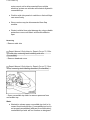
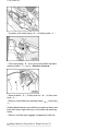
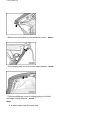
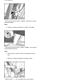
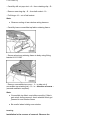
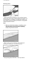
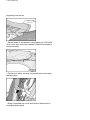
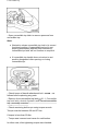
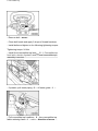
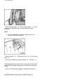
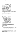
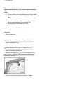
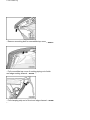
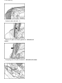
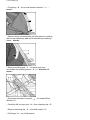
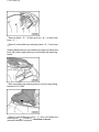
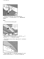
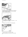
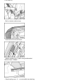
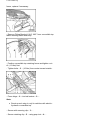
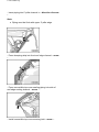
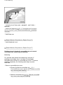
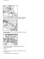
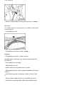
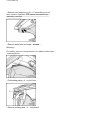
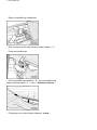
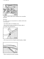
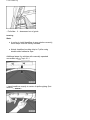
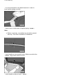
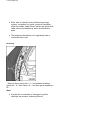
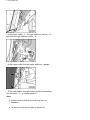
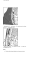
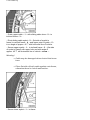
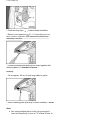
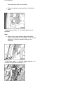
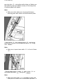
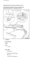
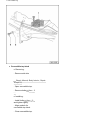
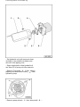
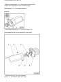
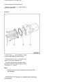
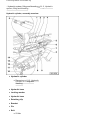
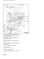
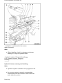
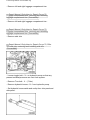
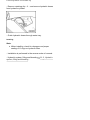
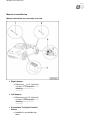
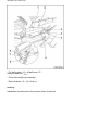
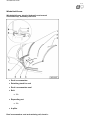
Volkswagen New Beetle: Convertible top 61 - 1 Volkswagen New Beetle Convertible top Safety precautions when working on convertible top Opening convertible top by operating open/close button Note: Observe safety instructions for electrical convertible tops. Before opening and closing convertible top, make sure there is enough room above. Safety precautions when working on electric-/hydraulic convertible top Warning! Tools For safety reasons, convertible top may only be opened or closed when vehicle is stationary. If opening or closing is interrupted, convertible top may spring and thus be lowered. Never drive as long as convertible top is not completely opened or closed. Do not attempt to close convertible top when anti-roll bar is activated. When opening or closing convertible top, make sure nobody gets injured by convertible top, convertible rods or moving covers at rear side windows. Do not open or close convertible top when vehicle is on a lift, a floor jack or over one side on curb. Convertible top Special tools, testers and auxiliary items required Closing Pliers VAS 6138 Staple Gun VAS 6148 Replacement staples VAS 6148/1 Pop Rivet Pliers VAS 5072 Fitting Bracket V.A.G 1887 Electric-/hydraulic convertible top, assembly overview Note: Manual convertible top 61-1, Manual convertible top, assembly overview . Convertible top Convertible top frame Convertible top, removing 61-1, Electric-/hydraulic convertible top, removing and installing Convertible top cover Replace 61-1, Convertible top cover, electric-/hydraulic convertible top, removing and installing Rear window is a component of convertible top cover Note : Entire convertible top cover must be replaced if rear window is damaged. Padding Convertible top Nut Replace 61-1, Padding, electric-/hydraulic convertible top and manual convertible top, removing and installing 10 Nm Bolt 12x 10 Nm Sealing band Convertible top headliner Bolt 50 Nm Front convertible top latch Replace 61-1, Convertible top headliner, electric/hydraulic and manual convertible top, removing and installing Removing 61-1, Convertible top front latch, electric-/hydraulic and manual convertible top assembly overview Front retaining latch Removing 61-1, Convertible top front latch, electric-/hydraulic and manual convertible top assembly overview Electric-/hydraulic convertible top, removing and installing Note: To operate convertible top hydraulically, rod flap Convertible top motors must not be disconnected from vehicle electrical system on vehicles with electric-/hydraulic convertible top. Position side trim panels in vehicle so that rod flaps can move freely. Servo motors may be disconnected from flap module. Protect vehicle from paint damage by using suitable protective covers and fabric reinforced adhesive tape. Removing - Remove side trim Repair Manual, Body Interior, Repair Group 70, Pillar and side trim; removing and installing side trim (Convertible) - Remove headrest cover Repair Manual, Body Interior, Repair Group 72, Rear seats, removing and installing backrest (Convertible) - Open convertible top latch to remove pressure from convertible top. Note: Illustration shows upper convertible top lock in its correct functional position. If convertible top lock is not properly assembled (different from illustration), convertible top latch will not function as designed. Convertible top If convertible top handle does not return to rest position designated after opening or closing convertible top: - Check torque of handle attachment bolt - arrow - as follows before replacing any parts: - Remove front convertible top latch 61-1, Convertible top front latch, electric-/hydraulic and manual convertible top - assembly overview . - Check remaining bolt torque using torque wrench: Torque must be between 20 and 27 Nm. If torque is less than 20 Nm: - Torque was incorrect and cause for malfunction. In either case, after remaining torque was checked: - Remove bolt - arrow - Clean bolt heads and apply 2 drops of thread hardener. - Install bolts and tighten to the following tightening torque: Tightening torque: 24 Nm - Install front convertible top latch 61-1, Convertible top front latch, electric-/hydraulic and manual convertible top assembly overview . Convertible top - If present, pull insert piping - 2 - off water guide - 1 - . - Pull insert piping - 2 - from top at convertible top fabric retaining frame - 1 - out in - direction of arrow - . - Remove bolts - 3 - (10 Nm) and nut - 4 - (10 Nm) from body - 1 - . - Remove convertible top retaining frame - 2 - from body 1 - . Sealing band between convertible top retaining frame and body can lead to light sticking of convertible top retaining frame. - Remove left and right luggage compartment side trim Repair Manual, Body Interior, Repair Group 70, Convertible top Luggage compartment trim; removing and installing luggage compartment side trim (Convertible) - Disconnect harness connector - 1 - for rear window on left and right. - Guide connection wiring for heated rear window into interior and unclip from side panel. - Open convertible top completely. - Unclip Convertible Top Open Position Switch F171 - 3 from hydraulic cylinder (right side only). - Pry securing clip - 4 - off piston rod - 1 - . - Pry piston rod - 1 - off ball head - 2 - using screwdriver. - Remove bolts - 2 - . - Close convertible top manually but do not lock. Convertible top - Remove bolt - 4 - . Note: Do not loosen base plate mounting bolts - 1 - and 3 - under any circumstance, otherwise basic settings of convertible top will be lost. - Lift convertible top at main mounting approx. 45 and remove out of convertible top box toward front (second mechanic required). Installing - Check sealing cord - 1 - on convertible top retaining frame, replace if necessary. - Place convertible top in convertible top box (second mechanic required). - Install bolts (50 Nm) for main mounting. - Position convertible top retaining frame in center and tighten nut - 4 - (10 Nm). - Tighten bolts - 3 - (10 Nm) from center toward outside. Note: Observe that convertible top retaining frame is at same "height" . Convertible top - Rest of installation is performed in the reverse order of removal. Convertible top cover, electric-/hydraulic convertible top, removing and installing Note: Protect chrome moldings and side trim against paint damage using suitable protective covers and fabric reinforced adhesive tape. Removing - Remove seatbench and headrest cover Repair Manual, Body Interior, Repair Group 72, - Cover edges of automatic anti-roll supports using tape or fabric. - Slide window completely open. - Open convertible top half way. - Observe safety precautions 61-1, Safety precautions when working on convertible top . - Using plastic wedge, remove clips - 11 - from front side of roof edge trim - 13 - , then remove clips - 12 - from rear side of roof front edge trim. Convertible top - Turn handle - 10 - 90 o and loosen roof edge trim - 13 - . - Pull front roof frame seal off roof frame - arrow - . Convertible top - Remove mounting bolt for convertible top cover - arrow . - Pull clamping strip out of front roof edge channel - arrow - . - Pull convertible top cover of sealing piping out of side roof edge sealing channel - arrow - . Note: A pliers helps ease this work step. Convertible top - Unhook cable with ball - 1 - . - Remove C-pillar roof frame gaskets off side convertible top frame. First remove inner edge, then pull in - direction of arrow - . Note: Carefully pull roof frame gasket off. There are some internal edges that may damage the gasket. - Pull piping out of C-pillar channel in - direction of arrow - . Note: A pliers helps ease this work step. Convertible top - Drill out pop rivet on frame - arrow - and remove using drift and hammer. Note: Observe routing and position of fabric and cable. - Drill out pop rivet on inner C-pillar - arrow - and remove using drift and hammer. Note: This rivet also holds C-pillar convertible top frame trim. Observe routing and position of plastic cable - Remove bolt - 1 - for convertible top cover tension Convertible top cable. - Pull tension cable downward in - direction of arrow - . - Close convertible top but do not lock. - Fold convertible top cover rearward. - Cut through clip using side cutter and open zip fastening. - Repeat this procedure for other two zip fasteners. - Pull convertible top cover forward and place it as it was before opening zip fasteners. - Pull convertible top headliner - 2 - from convertible top fabric retaining frame - 1 - out in - direction of arrow - . - Remove side water deflector (silver fabric). Convertible top - Pull piping - 2 - out of rear window channel - 1 - arrows - . - Remove bolts - 3 - (12x, 10 Nm) and nut - 4 - (10 Nm) from body - 1 - . - Remove convertible top retaining frame - 2 - from body 1 - . Sealing band between convertible top retaining frame and body can lead to light sticking of convertible top retaining frame. - Protect ending corners of aluminum frame - 2 - to avoid paint damage when getting into contact with body. - Lift aluminum frame - 2 - on outside of vehicle so that work on window frame components is made possible. - Disconnect harness connector - 1 - for Heated Rear Window Z1 . Convertible top - Carefully drill out pop rivet - 4 - from retaining clip - 5 . - Remove securing clip - 3 - from ball socket - 2 - . - Pull hinge - 6 - out of ball socket. Note: Observe routing of rear window wiring harness. - Carefully lower convertible top fabric retaining frame. - Secure aluminum retaining frame to body using fitting bracket V.A.G 1887 . - Remove convertible top cover - 1 - to side out of convertible top retaining rail - 2 - in - direction of arrow (second mechanic required). Note: Convertible top fabric must slide smoothly. If fabric gets stuck during removal, check whether fabric got jammed in rear window frame. Be careful when holding rear window. Installing Installation is the reverse of removal. Observe the Convertible top following notes: - Install convertible top headliner in rear window channel, starting from lower center upward leading to the sides. It is recommended to let engage convertible top headliner into rear window channel according to illustration, using plastic wedge and plastic hammer. Note: Make sure that both markings on headliner (upper and lower) align with notches on rear window channel. Make sure that headliner is distributed evenly along window channel. - Before closing each zip fastener, align marking on padding with marking on convertible top cover. - Using closing pliers VAS 6138 , close zip fastener Convertible top beginning from center. - Secure ends of zip fastener using staple gun VAS 6148 (3 to 5 mm from end of zip fastener). Make sure staple is closed correctly. - Pull tension cable into side convertible top cover using assisting wire. - Bring convertible top cover and tension cable back to original position again. Convertible top - Before installing roof edge strip into roof edge channel, align marking (strip) - 1 - of convertible top cover with center line of hole - 2 - of roof edge. It is recommended to ease pressing in roof edge strip using glass cleaner. Manual convertible top, assembly overview Note: Electric-/hydraulic convertible top 61-1, Electric/hydraulic convertible top, assembly overview . Convertible top Convertible top frame Convertible top cover Replace 61-1, Manual convertible top, cover, removing and installing Rear window is a component of convertible top cover Detail-pad convertible top cover Sewed on convertible top cover Removing Installing Sewed on convertible top cover Sewed on padding Nut Replace 61-1, Padding, electric-/hydraulic convertible top and manual convertible top, removing and installing Rear upholstering pad Topic 61-1 Tightening belt Topic 61-1 Padding Convertible top, removing 61-1, Manual convertible top, removing and installing 10 Nm Bolt 12x 10 Nm Sealing band Convertible top Convertible top headliner Bolt 50 Nm Front convertible top latch Replace 61-1, Convertible top headliner, electric/hydraulic and manual convertible top, removing and installing Removing 61-1, Convertible top front latch, electric-/hydraulic and manual convertible top assembly overview Front retaining latch Removing 61-1, Convertible top front latch, electric-/hydraulic and manual convertible top assembly overview Manual convertible top, removing and installing Removing Note: Protect vehicle from paint damage by using suitable protective covers and fabric reinforced adhesive tape. - Remove side trim Repair Manual, Body Interior, Repair Group 70, - Remove headrest cover Repair Manual, Body Interior, Repair Group 72, Convertible top - Open convertible top latch to remove pressure from convertible top. Note: Illustration shows convertible top lock in its correct functional position. If convertible top lock is not properly assembled (different from illustration), convertible top latch will not function as required. If convertible top handle does not return to rest position designated after opening or closing convertible top: - Check torque of handle attachment bolt - arrow - as follows before replacing any parts: - Remove front convertible top latch 61-1, Convertible top front latch, electric-/hydraulic and manual convertible top - assembly overview . - Check remaining bolt torque using torque wrench: Torque must be between 20 and 27 Nm. If torque is less than 20 Nm: - Torque was incorrect and cause for malfunction. In either case, after tightening torque was checked: Convertible top - Remove bolt - arrow - Clean bolt heads and apply 2 drops of thread hardener. - Install bolts and tighten to the following tightening torque: Tightening torque: 24 Nm - Install front convertible top latch 61-1, Convertible top front latch, electric-/hydraulic and manual convertible top assembly overview - If present, pull insert piping - 2 - off water guide - 1 - . - Pull convertible top headliner - 2 - from convertible top fabric retaining frame - 1 - out in - direction of arrow - . Convertible top - Open retaining clips - 2 - from tension cable - 1 - using screwdriver. Retaining clips remain clipped at same position. Note: To ease installation, observe original position of tension cable securing clips. - Remove bolts - 3 - (10 Nm) and nuts - 4 - (10 Nm) from body - 1 - . - Press convertible top retaining frame - 2 - off body - 1 . Sealing band between convertible top retaining frame and body can lead to light sticking of convertible top retaining frame. - Remove left and right luggage compartment side trim Repair Manual, Body Interior, Repair Group 70, Convertible top - Disconnect harness connector - 1 - for rear window on left and right. - Guide connection wiring for heated rear window into interior and unclip from side panel. - Open convertible top entirely. - Remove bolts - 2 - . - Close convertible top manually but do not lock. - Remove bolt - 4 - . Note: Do not loosen base plate mounting bolts - 1 - and 3 - under any circumstance, otherwise basic settings of convertible top will be lost. - Lift convertible top at main mounting approx. 45 and remove out of convertible top box toward front (second mechanic required). Installing Convertible top - Check sealing cord - 1 - on convertible top retaining frame, replace if necessary. - Place convertible top in convertible top box (second mechanic required). - Install bolts - 2 - and - 4 - (50 Nm) for main mounting. - Position convertible top retaining frame in center and tighten nut - 4 - (10 Nm). - Tighten bolts - 3 - (10 Nm) from center toward outside. Note: Observe that convertible top retaining frame is at same "height" . - Rest of installation is performed in the reverse order of removal. Convertible top Manual convertible top, cover, removing and installing Note: Protect vehicle from paint damage by using suitable protective covers and fabric reinforced adhesive tape. To ease installation, observe assembly position as well as work sequence for assembly and disassembly of convertible top cover. Always use new staples if necessary. Removing - Remove side trim Repair Manual, Body Interior, Repair Group 70, - Remove headrest cover Repair Manual, Body Interior, Repair Group 72, - Open convertible top half way. - Remove roof edge trim 61-1, Convertible top front latch, electric-/hydraulic and manual convertible top assembly overview . - Pull front roof frame seal off roof frame - arrow - . Convertible top - Remove mounting bolt for convertible top cover - arrow . - Pull convertible top cover of sealing piping out of side roof edge sealing channel - arrow - . - Pull clamping strip out of front roof edge channel - arrow - . Convertible top - Unhook cable with ball - 1 - . - Remove C-pillar roof frame gasket in - direction of arrow - . - Pull piping out of C-pillar channel in - direction of arrow - . Convertible top - If present, pull insert piping - 2 - off water guide - 1 - . - Pull headliner - 2 - from convertible top fabric retaining frame - 1 - out in - direction of arrow - . - Remove convertible top cover securing bolts from each pillar/bow. Note: To ease assembly, observe assignment of bolts to each bow/pillar. - Loose convertible top cover strongly outward from Cpillar - direction of arrow - . Use commercially available pliers and protect convertible top cover from damage using rag. - Drill out pop rivet on frame - arrow - and remove using drift and hammer. Convertible top - Drill out pop rivet on inner C-pillar - arrow - and remove using drift and hammer. - Pull tension cable downward in - direction of arrow - . - Remove convertible top cover detail-pad upward in direction of arrow - . Convertible top - Pull piping - 2 - out of rear window channel - 1 - arrow - . - Remove three mounting bolts on both sides on molding seal of rear upholstery pad and convertible top retaining frame - arrows - . - Remove molding seal - 1 - of corner bow from convertible top retaining frame - 2 - in - direction of arrow - . - Disconnect harness connector - 1 - for Heated Rear Window Z1 . - Carefully drill out pop rivet - 4 - from retaining clip - 5 . - Remove securing clip - 3 - from ball socket - 2 - . - Pull hinge - 6 - out of ball socket. Convertible top - Remove bolts - 3 - (10 Nm) and nut - 4 - (10 Nm) from body - 1 - . - Remove convertible top retaining frame - 2 - from body 1 - . Sealing band between convertible top retaining frame and body can lead to light sticking of convertible top retaining frame. - Bolt convertible top retaining frame to body using fitting bracket V.A.G 1887 . - Remove convertible top cover - 1 - from convertible top retaining rail - 2 - to side in - direction of arrow (second mechanic required). Convertible top - Remove mounting bolt from roof edge - arrow - . - Remove sealing piping of padding out of roof edge - 1 - , bow 1 - 2 - , bow 2 - 3 - in - direction of arrow - . - Fold convertible top cover to front in - direction of arrow - . Convertible top - Pull out convertible top to side in - direction of arrow . Note: To ease installation, observe assignment of each sealing piping of convertible top cover to each bow/roof edge. Installing - Slide convertible top cover in retaining rail from side (second mechanic required). Use lubricant for pulling in (e.g. silicone lubricant spray D 007 000 A2 ). - Insert molding seal of convertible top cover detail-pad - 1 - into channel of bow 1 - 2 - in - direction of arrow - . - Insert convertible top cover piping - 1 - into channel of bow 4 - 2 - in - direction of arrow - . Convertible top - To ease work sequence, insert convertible top cover/hinge - 1 - into ball socket - 2 - in - direction of arrow - . Note: Do not secure securing clip! - Align center lines (broken lines) - 1 - with hole - 2 - of middle bolt - 3 - in - direction of arrow - . - Thread bolt into bore of fabric edge strip - 4 - (as shown in illustration). - Thread middle bolt - 1 - with fabric edge strip - 2 - and headliner tightening belt - 3 - into hole of middle belt. Convertible top - Using a plastic hammer, press attachment of detail-pad roof edge strip with convertible top cover into roof edge channel in - direction of arrow - . - Insert sealing piping of padding into roof edge - 1 - , bow 1 - 2 - and bow 2 - 3 - - arrows - . Note: Observe correct seating of each sealing piping. - Install mounting bolt on roof edge - arrow - . - Insert sealing piping of convertible top cover into each bow. Convertible top - Secure tightening belt - 1 - to bow 2 - 2 - . To ease this work step, first thread mounting bolt - 3 - onto tightening belt - 1 - and onto headliner tightening belt - 4 - . Note: Observe correct seating of tightening belt - 1 (cross form, not twisted). - Align marking (line) - 1 - of roof edge mounting strip with hole in roof edge - 2 - . - Press roof edge mounting strip into roof edge channel. - Pull tension cable into side convertible top cover using assisting wire. Convertible top - Bolt on tension cable at rear. - Hook ball into front roof frame. - Adhere padding onto C-pillar using double-sided adhesive tape - arrow - . - Check sealing cord - 1 - on convertible top retaining Convertible top frame, replace if necessary. - Remove Fitting Bracket V.A.G 1887 from convertible top fabric retaining frame and body. - Position convertible top retaining frame and tighten nut 4 - (10 Nm) first. - Tighten bolts - 3 - (10 Nm) from center toward outside. - Press hinge - 6 - into ball socket - 2 - . Note: Previous work step is only for vehicles with electric/hydraulic convertible top. - Secure with securing clip - 3 - . - Secure retaining clip - 5 - using pop rivet - 4 - . Convertible top - Connect harness connector - 1 - . - Press piping into rear window channel - arrow - . - Press in convertible top headliner - 2 - on convertible top fabric retaining frame - 1 - against - direction of arrow . Note: Start at center. - If installed, secure water guide - 1 - with insert piping - 2 - . Convertible top - Using screwdriver, guide long tension strap - 1 - through securing strip of convertible top padding - 2 - and pull out. To do so, place screwdriver in hole of long tension strap and pull out long tension strap in - direction of arrow - . - Place long tension strap - 2 - behind short tension strap 1 - . - Align mounting bores of both tension straps. - Secure both tension straps to frame using pop rivets - 3 . Note: Observe correct position of tension straps (as shown in illustration). - Open convertible top half way. Convertible top - Insert piping into C-pillar channel in - direction of arrow - . Note: Piping must be flush with upper C-pillar edge. - Press clamping strip into front roof edge channel - arrow - . - Press convertible top cover sealing piping into side of roof edge sealing channel - arrow - . - Install convertible top cover securing bolt - arrow - . Convertible top - Install front roof frame seal - arrow A - and C-pillar arrow B - . - Install roof edge trim 61-1, Convertible top front latch, electric-/hydraulic and manual convertible top - assembly overview . - Install side trim Repair Manual, Body Interior, Repair Group 70, - Install headrest cover Repair Manual, Body Interior, Repair Group 72, Padding, electric-/hydraulic convertible top and manual convertible top, removing and installing Removing For vehicles with manual convertible top, removal of padding at roof edge, bow 1 and bow 2 was already described with removal of convertible top cover. To remove padding completely, the following work steps must be observed. - Remove convertible top cover: Electric-/hydraulic convertible top 61-1, Convertible top cover, electric-/hydraulic convertible top, removing and installing Manual convertible top 61-1, Manual convertible top, cover, removing and installing Convertible top - Remove C-pillar padding securing bolts from convertible top retaining frame and pull out sealing piping - arrow - . - Guide connection wire for heated rear window and hinge through padding. - Remove securing bolt for headliner rubber cable on convertible top frame. Warning! For safety reasons, keep tension on rubber cable when removing bolt. - Pull rubber cable out of headliner loop. Convertible top - Remove piping from roof edge. - Open convertible top half way. - Remove convertible top headliner as far as rear bow 61-1, Convertible top headliner, electric-/hydraulic and manual convertible top, removing and installing . - Remove securing bolts - 1 - from bow 2 and 4 from side. - Remove center securing bolts from bow 2 and 4. - Remove guiding rubber cable securing bolt from bow 3 to convertible top frame tension cable - arrow - . Convertible top - Remove rubber cable securing bolt from bow 2 - arrow . Warning! For safety reasons, keep tension on rubber cable when removing bolt. - Fold padding to rear. - Pull padding out of bow to side - arrow - . Installing - Pull padding into bow 2, 4 and rear bow. Use lubricant for pulling in (e.g. silicone lubricant spray D 007 000 A2 ). - Press piping into roof edge. - Align padding evenly. - Install center securing bolts at bow 2 and 4. - Slide beading strips, tension strap and padding into bows 2 and 4. - Install securing bolts into piping on sides of bows 2 and 4. - Secure rubber cable with bolt to convertible top frame. - Install bolt for guiding rubber cable and padding loop to Convertible top bow 3 for convertible top frame tension cable. - Guide connection wire for heated rear window and hinge through padding. - Guide rubber cable through headliner loop. - Press padding sealing piping in at convertible top fabric retaining frame and secure using bolts. Convertible top headliner, electric-/hydraulic and manual convertible top, removing and installing Removing Note: To operate convertible top hydraulically, rod flap motors must not be disconnected from vehicle electrical system on vehicles with electric-/hydraulic convertible top. Position side trim panels in vehicle so that rod flaps can move freely. Servo motors may be disconnected from flap module. Protect vehicle from paint damage by using suitable protective covers and fabric reinforced adhesive tape. Always use new staples if available. - Remove side trim Repair Manual, Body Interior, Repair Group 70, - Remove headrest cover Repair Manual, Body Interior, Repair Group 72, - Open convertible top half way. Warning! Observe safety precautions when working on convertible top 61-1, Safety precautions when working on convertible top . Convertible top - Remove roof edge trim 61-1, Convertible top front latch, electric-/hydraulic and manual convertible top assembly overview . - Remove bolts from roof edge - arrows - . Warning! For safety reasons, keep tension on rubber cable when removing bolts. - Pull sealing piping - 1 - out of bow. - Remove molding seal - 1 - from bow 2. Convertible top - Pull insert profile - 1 - of dart out of bow molding seal. - Pull darts between bow 3 and retaining frame. - Remove molding seal - 1 - from bow 4. - Remove C-pillar roof frame gasket in - direction of arrow - . Convertible top - Pull convertible top cover piping out of C-pillar channel in - direction of arrow - . - Loosen bonding - 1 - from C-pillar. - Drill out pop rivet for tension cable. - Drill out pop rivet for tension cable retainer - 1 - . Convertible top - Open convertible top completely. - Drill out pop rivet for lower tension cable retainer - 1 - . - Close convertible top. - Pull convertible top headliner - 2 - from convertible top fabric retaining frame - 1 - out in - direction of arrow - . - Pull piping out of rear window channel - arrow - . Convertible top - Remove rubber cable bolt for headliner from convertible top frame. Warning! For safety reasons, keep tension on rubber cable when removing bolt. - Pull rubber cable out of headliner loop. - Remove bolt securing convertible top rubber cable to convertible top retaining frame. - Drill out pop rivet for roof spoiler cassette piping - arrow - . - Remove piping form spoiler cassette. Convertible top - Pull slide - 1 - downward out of guide. Installing Note: In order to install headliner to rear window correctly, these steps must be strictly followed. Attach headliner bonding strip to C-pillar using double-sided adhesive tape. Additional steps for vehicles with manually operated convertible top Topic 61-1 - Insert headliner exactly in center of spoiler piping (first fixation) - arrows - . Convertible top - It is recommended to use plastic hammer in order to insert spoiler piping correctly. - Insert rivets on both sides of spoiler piping - arrow - . Note: Before continuing, convertible top should be opened half way. This eases installation of headliner. - Insert headliner into second fixation. Make sure white line - arrow - aligns with center of cover. - Install headliner above frame - arrow - . Convertible top - Attach headliner to third fixation - arrow - . - Attach headliner to fourth fixation - arrow - . - Install tension cables (convertible top headliner, tensioning system - assembly overview): 11.03 61-1, Headliner tensioning system, assembly overview 11.03 12.03 61-1, Headliner tensioning system, removing and installing 11.03 - Insert headliner into fifth fixation - arrow A - in area of front convertible top latch - arrow B - . Convertible top - Install securing bolt. - Install roof edge trim. - Install tension cable - arrow - on both sides of convertible top frame. - Convertible top frame is located under rear window - Convertible top circle - - Open convertible top cover to install headliner at rear window and leave a space of approx. 10 cm between convertible top latch and convertible top cover. - Install one side of headliner - arrow - on rear window, first on upper side of rear window and then from bottom. Repeat this step on other side. - To prevent headliner from loosening at sides, close convertible top cover without pulling handle. - Pull all four corners of headliner in direction of - arrows . Convertible top - Install upper and lower center parts of headliner. Starting at top, press headliner against rear window. Note: If headliner cannot be inserted correctly at bottom, loosen upper center of headliner and insert again, from bottom to top. - When inserting headliner at rear window, plastic hammer should be used as shown. For vehicles with manually operated convertible top only. The following work steps must be additionally performed on vehicles with manual convertible top. - If present, insert new staples in molding seal - 1 - of rear upholstering pad - arrows - (4 per side). Convertible top Note: Distance between staples is not relevant. - If necessary, insert convertible top cover - 1 - into convertible top retaining rail - 2 - opposite - direction of arrow - . - Insert molding seal - 1 - of rear upholstery pad into convertible top retaining frame - 2 - in - direction of arrow - . - Install three securing bolts on both sides on molding seal of rear upholstery pad and convertible top retaining frame arrows - . Continuation for vehicles with electric-/hydraulic convertible top Rest of installation is performed in the reverse order of Convertible top removal. Headliner tensioning system, assembly overview 11.03 61-1, Headliner tensioning system, Vehicles 12.03 assembly overview 12.03 . Convertible top cover Replacing: Electric-/hydraulic convertible top 61-1, Convertible top cover, electric-/hydraulic convertible top, removing and installing Manual convertible top 61-1, Manual convertible top, cover, removing and installing Convertible top frame Removing convertible top: Electric-/hydraulic convertible top 61-1, Convertible top Electric-/hydraulic convertible top, removing and installing Convertible top headliner Tied to guide rail headliner ( Item - 4 - ) Secured to frame using pop rivet Always replace Middle deflector Secured to frame using pop rivet Lower deflector eyelet Secured to frame using pop rivet Upper deflector Item Secured with clips to reinforcement plate ( - 11 - ) Lower cable track guide with eyelet Replace 61-1, Convertible top headliner, electric/hydraulic and manual convertible top, removing and installing Guide rail headliner Manual convertible top 61-1, Manual convertible top, removing and installing Secured to frame using pop rivet Deflecting cable with eyelet Secured to frame and to guide with pop rivet Convertible top Inserted in upper cable track guide with cable shoe ( Item - 10 - ) Upper cable track guide with eyelet Tied to guide rail headliner ( Item - 4 - ) Secured to frame using pop rivet Always replace Reinforcement plate With securing clips In headliner Item - 3 - Tension strap with eyelet Secured to reinforcement plate ( Item - 11 - ) In headliner Item - 3 - Headliner guide rail Secured to frame using three pop rivets Secured to guide rail headliner ( Item - 4 - ) Headliner tensioning system, removing and installing 11.03 61-1, Headliner tensioning system, Vehicles 12.03 removing and installing 12.03 . Note: Open or close (half way open position is suitable) convertible top as needed to ease working (repair work, servicing) on headliner tensioning system. Before opening and closing convertible top, make sure there is enough room above. Convertible top Each side of vehicle has a headliner tensioning system, consisting of a guide, guide rail headliner (with tied cables, cable shoes, cable track guide with cable shoes and deflectors) and a reinforcement plate. The following description is for right-hand side of convertible top cover. Removing - Remove three pop rivets - 1 - and release headliner guide rail - 3 - from frame - 2 - and from guide headliner 4 - . Note: If guide rail is scratched or damaged or plastic shavings are present, replace guide rail. Convertible top - Remove two pop rivets - 1 - from frame and loosen cable shoes. Note: Observe installation position of cable shoes. If necessary, use drift to remove pop rivet. - To remove guide rail headliner - 1 - from reinforcement plate - 2 - , unclip securing clips - 3 - of reinforcement plate using screwdriver. To do this, start this work step from bottom - arrow - . Convertible top - Untie both cables - 1 - from guide rail headliner and pull out of deflector (center), out of deflector eyelet (bottom) and out of deflector (top) - arrows - (upper deflector is not shown in illustration). Note: When using new guide rail headliner, cut cables to ease work step. Observe installation position of cables on guide rail headliner in deflectors and deflector eyelet (bottom). - Push securing clips - 1 - inward toward headliner. - Remove roof edge trim 61-1, Convertible top front latch, electric-/hydraulic and manual convertible top assembly overview . Convertible top - Remove securing bolt at roof edge and pull out tension strap with reinforcement plate in - direction of arrow - . Installing - Tie an approx. 92 cm (3 feet) long cable to tension strap cable shoe. - Insert reinforcement plate with tension strap into headliner - arrow - . Note: Use strong flexible cable (long enough to insert into headliner) in form of "Y" at end to ease insertion of reinforcement plate. Observe original installation position of reinforcement plate. - Press securing clips - 1 - of reinforcement plate out of headliner. Note: Remove new deflectors and deflector eyelet from cables when using new guide rail headliner. Only use new deflectors and new deflector eyelet when deflectors and deflector eyelet are damaged. Convertible top - Guide lower cable - 1 - through deflector (center) - 2 and then through deflector eyelet - 3 - . - Guide upper cable through upper deflector - arrow - . - Guide both cables through holes in guide rail headliner and tie knots - 1 - at original position. Note: Cables must be tied at rear side of guide rail headliner. Tie knot as close as possible to cable end. Convertible top - Secure guide rail headliner - 1 - to reinforcement plate 2 - . To do so, carefully press securing clips - 3 - together using pliers. Observe correct seating of securing clips to holes of guide rail headliner. Note: Make sure cables are not jammed between guide rail headliner and reinforcement plate. - Slide guide - 1 - into guide rail headliner - 2 - . Note: Upper cable - 3 - must be routed behind guide. Lower cable - 4 - must be routed in front of guide. Convertible top - Insert guide - 1 - into frame - 2 - and secure two lower points - 3 - using pop rivets. - Bring upper cable - 2 - behind cross rail - 1 - and over extended frame - 3 - . Note: Guide cable through highest and rearmost point. Convertible top - Guide upper cable - 1 - with sliding cable shoe - 2 - to inclined frame - 3 - . - Rivet sliding cable eyelet - 2 - (flat side of eyelet to frame) to vertical frame - 4 - and upper point of guide - 5 in an angle of approx. 45 with horizontal line of vehicle. - Secure upper eyelet - 1 - to inclined frame - 3 - (flat side of eyelet to frame) with upper hole and with angle of approx. 45 with horizontal line of vehicle - arrow - . Warning! Cable may be damaged when riveted into lower bore. Place flat side of both cable eyelets onto frame, otherwise there is risk of malfunction. - Secure lower eyelet - 1 - to frame. Convertible top - Pull cable secured to eyelet out until eyelet is reached arrow - . - Install strap eyelet. - Untie cable from eyelet. - Open and, if necessary, close convertible top cover to check correct operation of convertible top cover. - Install roof edge trim after finishing repair work on headliner tensioning system 61-1, Convertible top front latch, electric-/hydraulic and manual convertible top assembly overview . Headliner tensioning system, assembly overview 12.03 Vehicles 11.03 61-1, Headliner tensioning system, assembly overview 11.03 . Convertible top Convertible top cover Convertible top frame Convertible top headliner Retaining plate with cables Secured to reinforcement plate with retaining clips ( Item - 12 - ) Lower cable track guide with eyelet Secured to retaining plate with cable Item - 4 - Secured to frame with rivet Always replace Middle deflector Secured to frame with rivet Convertible top Lower deflector eyelet Upper deflector Secured to frame with rivet Secured to frame with rivet Sliding cable with eyelet Secured to frame with rivet Inserted into upper cable Item - 10 - Upper cable track guide with eyelet Secured to retaining plate with cable Item - 4 - Secured to frame with rivet Always replace Weaving guide Secured to reinforcement plate with retaining clips ( Item - 12 - ) Secured between retaining plate and reinforcement plate Item - 12 - with cable Item - 4 - Reinforcement plate With retaining clips In headliner Item - 3 - Tension strap with eyelet Secured to reinforcement plate Item - 12 - In headliner Item - 3 - Guide Secured to frame with two rivets Convertible top Inserted in weaving guide Item - 11 - Headliner tensioning system, removing and installing 12.03 Vehicles 11.03 61-1, Headliner tensioning system, removing and installing 11.03 . Note: Open or close (half way open position is suitable) convertible top as needed to ease working (repair work, servicing) on headliner tensioning system. Before opening and closing convertible top, make sure there is enough room above. Each side of vehicle has a tensioning system, consisting of a guide, weaving guide, retaining plate with cable (eyelets and deflectors) and a reinforcement plate (with cable attached and eyelet in inner trim). The following description is for right-hand side of convertible top cover. Removing - Remove rear panel trim Repair Manual, Body Interior, Repair Group 70, Convertible top - Remove two rivets - 1 - and loosen guide - 2 - from frame - 3 - and weaving guide - 4 - . Note: Replace guide if scratched, damaged or plastic shavings are present. Observe installation position of eyelets - 5 - and do not damage when removing rivet. - Drill out three rivets - 1 - from frame and loosen eyelets as well as weaving guides - 2 - . Note: Observe installation position of cables. Convertible top Observe installation position of weaving guides - 2 at lower cable end. If necessary, use drift to drive out. - To remove retaining plate with cable - 1 - from reinforcement plate - 2 - in headliner, unclip retaining clips - 3 - from retaining plate, starting at bottom, using screwdriver - arrow - . - Release weaving guide - 4 - from reinforcement plate 2 - at inner headliner. - Remove both cables - 1 - from retaining plate with cable and remove from lower, middle and upper deflectors as well as from handle trim - arrows - (upper deflector and upper headliner handle are not shown in this illustration). Note: When using a new retaining plate with cables, cut cables to ease procedure. Observe installation position of cables in retaining plate with cables, deflectors and headliner handles. Convertible top - Push securing clips - 1 - inward toward headliner. - Remove roof edge trim 61-1, Convertible top front latch, electric-/hydraulic and manual convertible top assembly overview - Loosen securing bolts and pull out strap together with retaining plate in - direction of arrow - . Installing - Tie an approx. 92 cm (3 feet) long cable to eyelet. - Insert retaining plate with strap in inner headliner - arrow - . Note: Use strong flexible piece of wire (long enough to insert into headliner) in form of "Y" at end of wire, to Convertible top insert retaining plate into headliner. Observe original mounting position of retaining plate. - Press securing clips - 1 - of retaining plate out of headliner. Note: When using a new retaining plate with cables, remove new deflectors from cables. Only use new deflectors if already installed deflectors are damaged. - Guide lower cable - 1 - through middle deflector - 2 and then through lower deflector - 3 - . Convertible top - Guide upper cable - 1 - through upper deflector - 2 and then through headliner handle - 3 - in - direction of arrow - . - Insert both cables in retaining plate with cable and tie in initial position - 1 - . Note: Knots must be located on back side of retaining plate with cables. Tie knot as close to cable end as possible. - Secure weaving guide - 1 - with securing clips - 3 - to reinforcement plate - 2 - . - Secure retaining plate with cables - 1 - to reinforcement plate - 2 - (inside of headliner). Carefully press together Convertible top securing clips - 3 - using pliers while doing so. Make sure that securing clips are seated correctly in mounting holes of retaining plate with cables. Note: Make sure that cables are not jammed between retaining plate with cables and reinforcement plate. - Insert guide - 1 - into weaving guide - 2 - and secure lower point of guide to convertible top frame - 4 - using rivet - arrow - . Note: Make sure to pass lower cable - 3 - in front of frame - 4 - . - Secure upper point of guide - 1 - and eyelets - 2 - to convertible top frame - 3 - using rivet - arrow - . Note: Make sure that guide - 1 - is installed in upper and lower point on inner side of convertible top frame - 3 Convertible top - and eyelets - 2 - are installed on outer side of convertible top frame. Observe original position of eyelets. - Guide upper cable - 2 - behind cross rail - 1 - and over extended frame - 3 - . Note: Guide cable through highest and rearmost point. - Guide upper cable - 1 - with sliding cable eyelet - 2 - to inclined frame - 3 - . - Rivet sliding cable eyelet - 2 - (flat side of eyelet on frame) to vertical convertible top frame - 4 - in an angle of 45 with horizontal line of vehicle. - Rivet sliding cable eyelet - 1 - (flat side of eyelet on frame) to inclined frame - 3 - in an angle of 45 with horizontal line of vehicle - arrow - . Warning! Convertible top Cable may be damaged when riveted into lower bore. Place flat side of both cable eyelets onto frame, otherwise there is risk of malfunction. - Rivet lower eyelet - 1 - and weaving guides - 2 - to frame - 3 - . Note: Observe that weaving guides are installed between frame - 3 - and eyelet - 1 - . - Pull string tied to strap eyelet until eyelet is reached arrow - . - Install cable eyelet. - Untie string from cable eyelet. - Open/close convertible top to check correct operation. - After completing repair work, install roof edge in headliner tensioning system 61-1, Convertible top front latch, electric-/hydraulic and manual convertible top assembly overview . - Install rear side trim Convertible top Repair Manual, Body Interior, Repair Group 70, Convertible top front latch, electric-/hydraulic and manual convertible top - assembly overview Linkage Securing clip Plate Bolt 10 Nm Face plate Removing: - Remove securing clip Item - 6 - . - Remove pins . Item - 8 - Convertible top Circlip Bolt 10 Nm Pin Bolt Handle Removing: - Remove socket head bolt from side. Clip Clip Roof edge trim Removing: - Unclip front and rear. - Turn 90 and remove over handle Item - 10 - . Convertible top lock, removing and installing Convertible top Roof crossmember Bolt Micro switch Plate Convertible top lock Removing: - Remove roof crossmember trim Repair Manual, Body Interior, Repair Group 70, Roof trim; removing and installing roof crossmember trim (Convertible) - Disconnect micro switch harness connector. - Remove bolt Item - 6 - Convertible top . Installing: - Installation is the reverse order of removal. Bolt 10 Nm Note: Convertible top can be adjusted via elongated holes in convertible top lock - 5 - . Convertible top must be seated centrally on roof crossmember and evenly on A-pillar. Rear convertible top latch, electric-/hydraulic convertible top, assembly overview Note: Manual convertible top 61-1, Rear convertible top latch, manual convertible top, assembly overview . Convertible top Convertible top latch Removing: - Remove side trim. Repair Manual, Body Interior, Repair Group 70, - Open convertible top. - Disconnect harness connector Item - 6 - . - Remove bolts - . Item - 3 Installing: - Install bolts Item - 3 and tighten lightly. - Disconnect harness connector Item - 6 - . Convertible top - Align module for convertible top latch. - Close convertible top. - When convertible top has engaged, tighten bolts Item - 3 - . - Then perform function test. Washer 7x Bolt 10 Nm 7x Cable for emergency release Adjusting motor Harness connector Micro switch (convertible top closed) Micro switch (convertible top open) Rear convertible top latch, manual convertible top, assembly overview Convertible top Convertible top latch Removing: - Remove side trim Repair Manual, Body Interior, Repair Group 70, - Open convertible top. - Remove bolts - . Item - 3 Installing: - Install bolts Item - 3 and tighten lightly. - Align module for convertible top latch. - Close convertible top. Convertible top - When convertible top has engaged, tighten bolts Item - 3 - . - Then perform function test. Washer 6x Bolt 10 Nm 6x Electric/hydraulic convertible top 61 - 2 Electric/hydraulic convertible top Assembly overview Right hydraulic cylinder Removing 61-2, Hydraulic cylinder, removing and installing Convertible Top Open Position Switch Installed only on right side Unclip from hydraulic cylinder - 1 - Hydraulic hoses Removing and installing 61-2, Hydraulic hoses, Electric/hydraulic convertible top removing and installing Convertible Top Control Module j256 In luggage compartment, right rear Further information Electrical Wiring Diagrams, Troubleshooting and Component Locations binder Left hydraulic cylinder Removing 61-2, Hydraulic cylinder, removing and installing Buffer plugs Oil filler plug Hydraulic Pump Hydraulic oil must stand between min- and max marking with convertible top open Right Contact Switch, cover installed F156 or left F155 Unthreading toggle bolt releases pressure from hydraulic system and convertible top can be operated by hand. Fill level indicator Removing and installing 61-2, Hydraulic pump, removing and installing Toggle bolt 5 Nm 2x Convertible Top Operation Electric/hydraulic convertible top Switch E137 Located in center console Hydraulic system, filling and bleeding When hydraulic pump is overloaded, a thermo fuse interrupts circuit and system is switched off up to a maximum of 35 seconds. After that, the system is functionally ready again. Behind a rubber cover of left trim in luggage compartment, a toggle handle is installed on the hydraulic unit. By turning toggle toward left, the system becomes without pressure and convertible top can be operated manually. Filling hydraulic system Note: Electric-/hydraulic convertible top pertains to a closed hydraulic system. As a rule, a filling is only required after opening the hydraulic circuit (e.g. after replacing parts). Due to the lift and displacement effects of the hydraulic piston rods, hydraulic oil level must only be determined when convertible top is open. Warning! Do not fill system above "Max" marking. Otherwise the pressure in the system could grow so large that damage cannot be prevented. - Remove left luggage compartment trim Repair Manual, Body Interior, Repair Group 70, Luggage compartment trim; removing and installing luggage compartment trim (Convertible) - To fill, convertible top must be opened, the actual oil level can only be determined when in an opened state. Electric/hydraulic convertible top - Unscrew oil filler plug - 1 - . - Oil for convertible top hydraulics: G 002 00 . - Top off hydraulic oil only until oil level is between "Min" and "Max" marking - 2 - . - Use a fill container for filling the hydraulic oil. - Fill container must only be used exclusively for this purpose in order to prevent hydraulic oil impurities by other oils. - Tighten oil filler plug - 1 - (5 Nm). Bleeding hydraulic system Hydraulic system is self-bleeding. System is bled after several operations. - Unscrew oil filler plug - 1 - . - Switch ignition on and off again, leave key inserted in ignition lock. - Operate convertible top switch and open and close convertible top 4 to 5 times. - The system is bled automatically by opening and closing several times. - Convertible top must be able to be opened and closed smoothly and without hitching. Electric/hydraulic convertible top - With convertible top open, oil level must be located between "Min" and "Max" marking - 2 - , correct if necessary. - Tighten oil filler plug - 1 - (5 Nm). Hydraulic pump, removing and installing Warning! Hydraulic system is sensitive to any ingress of dirt. As soon as system is opened, corresponding components must be covered so that no dirt can enter hydraulic system. Before working on electrical system: Disconnect battery ground (GND) strap. Removing Note: Obtain radio code before disconnecting battery. - Disconnect Ground (GND) strap from battery Repair Manual, Electrical Equipment, Repair Group 27, - Remove left luggage compartment trim Repair Manual, Body Interior, Repair Group 70, - Disconnect harness connector - 5 - from Convertible Top Hydraulic Pump V118 . - Loosen toggle bolt - 1 - so that residual pressure can escape the system, then tighten again. - Mark hydraulic lines - 3 - before disconnecting. Remove Torx bolts - 2 - (7 Nm). Electric/hydraulic convertible top - Carefully pull hydraulic lines - 3 - out of openings. - Remove hex nut - 4 - (5 Nm). Installing Installation is performed in the reverse order of removal. Note: Check for damage and proper fitting of O-rings when installing hydraulic lines. After installation of hydraulic pump, hydraulic system must be filled and bled again 61-2, Hydraulic system, filling and bleeding . After connecting battery, vehicle options (radio, clock, electric window regulator) must be checked according to repair manual and/or user manual. Pump wheel for hydraulic pump, assembly overview Electric/hydraulic convertible top Motor for hydraulic pump Torx bolts Always replace 5 Nm Pump wheel Removing and installing 61-2, Hydraulic pump, removing and installing Removing 61-2, Pump wheel for hydraulic pump, removing and installing Sealing ring Always replace Sealing ring is contained in repair set Hydraulic Pump Pump wheel for hydraulic pump, removing and installing Removing - Remove hydraulic pump removing and installing . 61-2, Hydraulic pump, Note: Hydraulic system is sensitive to any ingress of dirt. Components must be covered as soon as the system is opened. Before removing the hydraulic unit, place a container under pump and catch escaping oil. Electric/hydraulic convertible top - Set hydraulic unit with reservoir down vertically in an suitable container and secure it from tipping over. - Open toggle bolt so that hydraulic oil can flow out of pump unit into reservoir. - Remove Torx bolts - 2 - (5 Nm, always replace) and disconnect motor - 1 - from hydraulic pump. - Remove pump wheel - 1 - from drive shaft - 2 - . Electric/hydraulic convertible top - Remove metal tongue - 3 - from pump housing (metal tongue will be damaged if left in pump housing). Metal tongue - 3 - is no longer required. Installing - Press new pump wheel - 1 - onto drive shaft - 2 - . Pump wheel fits only in one position on drive shaft. - Pull off old O-ring - 4 - from hydraulic pump - 5 - and replace with new O-ring. Electric/hydraulic convertible top - Position motor - 1 - with new pump wheel onto hydraulic pump - 5 - and install with new bolts - 2 - (bolts - 2 - are micro-encapsulated, tightening torque 5 Nm). - Install hydraulic pump and installing . 61-2, Hydraulic pump, removing - Hydraulic system, filling and bleeding system, filling and bleeding . Oil reservoir, assembly overview Torx bolts 2 Nm Always replace bolts Oil reservoir Removing 61-2, Oil reservoir, removing and 61-2, Hydraulic Electric/hydraulic convertible top installing Sealing ring Always replace Sealing ring is contained in repair set Hydraulic Pump Oil reservoir, removing and installing Removing - Remove hydraulic pump removing and installing . 61-2, Hydraulic pump, Note : Before removing oil reservoir, place container under pump and catch escaping oil. - To remove, loosen Torx bolts - 1 - and Electric/hydraulic convertible top catch escaping oil while doing so. - Remove Torx bolts - 1 - and carefully pull off oil reservoir. Installing - Coat O-ring - 3 - with hydraulic oil and insert into groove on pump housing. - Coat oil reservoir - 2 - on inside in the area of O-ring with hydraulic oil. - To install, slide on oil reservoir using turning motions and always tighten new Torx bolts - 1 - (2 Nm). Note : Always observe torque, otherwise oil reservoir will be damaged. - Install hydraulic pump and installing . 61-2, Hydraulic pump, removing Electric/hydraulic convertible top - Hydraulic system, filling and bleeding system, filling and bleeding . Hydraulic cylinder, assembly overview Hydraulic cylinder Removing 61-2, Hydraulic cylinder, removing and installing Hydraulic hose Locking washer Hydraulic hose Retaining clip Bracket Pin Bolt 23 Nm 61-2, Hydraulic Electric/hydraulic convertible top 2x Convertible Top Open Position Switch Installed only on right side Screwdriver Ball head Cap Securing clip Piston rod Hydraulic cylinder, removing and installing Note: Hydraulic system is sensitive to any ingress of dirt. As soon as system is opened, corresponding components must be covered so that no dirt can enter hydraulic system. Removing - Open convertible top. - Remove side trim Repair Manual, Body Interior, Repair Group 70, Electric/hydraulic convertible top - Loosen toggle bolt on hydraulic pump so that any present residual pressure can vent from the system. - Open cap - 12 - of Convertible Top Open Position Switch. - Pry securing clip - 13 - off piston rod 14 - . - Pry piston rod - 14 - off ball head using screwdriver - 10 - . - Close convertible top manually. - Remove bolts - 8 - . - Remove retaining clip - 5 - . - Remove hydraulic hoses - 2 - and - 4 . Installing Electric/hydraulic convertible top - Installation is performed in the reverse order of removal. Note : When installing, check for damages and proper seating of O-rings on hydraulic lines. - Hydraulic system, filling and bleeding 61-2, Hydraulic system, filling and bleeding . Hydraulic hoses, removing and installing Note: Hydraulic system is sensitive to any ingress of dirt. As soon as system is opened, corresponding components must be covered so that no dirt can enter hydraulic system. Removing Electric/hydraulic convertible top - Remove left and right luggage compartment trim. Repair Manual, Body Interior, Repair Group 70, Luggage compartment trim, removing and installing luggage compartment trim (Convertible) - Remove left and right luggage compartment trim . Repair Manual, Body Interior, Repair Group 70, Luggage compartment trim, removing and installing luggage compartment trim (Convertible) - Remove side trim Repair Manual, Body Interior, Repair Group 70, Pillar and side trim; removing and installing side trim (Convertible) - Loosen toggle bolt - 3 - on hydraulic pump so that any present residual pressure can vent from system. - Remove Torx bolt - 1 - (7 Nm). - Remove hydraulic hoses - 2 - from hydraulic pump. - Set hydraulic hoses aside and unclip from trim panel and side panel. Electric/hydraulic convertible top - Remove retaining clip - 1 - and remove hydraulic hoses from hydraulic cylinder. - Guide hydraulic hoses through water tray. Installing Note: When installing, check for damages and proper seating of O-rings on hydraulic lines. - Installation is performed in the reverse order of removal. - Hydraulic system, filling and bleeding system, filling and bleeding . 61-2, Hydraulic Manual convertible top 61 - 3 Manual convertible top Manual convertible top, assembly overview Right damper Left damper Removing 61-2, Hydraulic cylinder, removing and installing Removing 61-2, Hydraulic cylinder, removing and installing Convertible Top Open Position Switch Installed in convertible top latch Manual convertible top Supplied as replacement part Allocation Parts catalog Convertible Top Control Module J256 On 13-pin secondary relay carrier above relay carrier Further information Electrical Wiring Diagrams, Troubleshooting and Component Locations binder Damper, assembly overview Shock absorber Removing 61-3, Shock absorber, removing and Manual convertible top installing Locking washer Bracket Pin Bolt 18 2x 1.8 Nm Screwdriver Ball head Ball socket Shock absorber, removing and installing Removing To remove and install damper, Torx screwdriver T 45, 100 mm long (commercially available) must be used. - Open convertible top. - Remove side trim Repair Manual, Body Interior, Repair Group 70, Manual convertible top - Pry ball socket - 8 - off ball head - 7 using screwdriver - 6 - . - Close convertible top manually. - Remove bolts - 5 - (2x, 18 Nm). Installing Installation is performed in the reverse order of removal. Windshield frame 61 - 4 Windshield frame Windshield frame, electric-/hydraulic and manual convertible top, assembly overview Roof crossmember Retaining track for seal Roof crossmember seal Bolt Expanding nut 15x 15x A-pillar Roof crossmember seal and retaining rail, electric- Windshield frame /hydraulic and manual convertible top, removing and installing Removing - Open convertible top. - Remove seal - 1 - from retaining rail. Note : Ensure proper seating in retaining track - 2 - when installing seal - 1 - . - Remove bolts - 4 - . - Remove retaining rail - 2 - . Installing Installation is performed in the reverse order of removal.