1
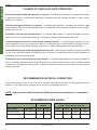
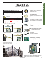
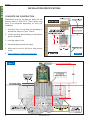
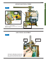
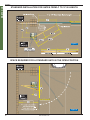
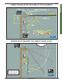
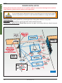
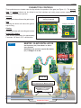
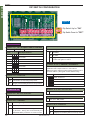
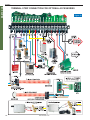
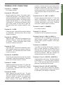
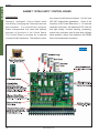
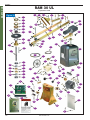
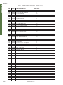
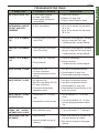
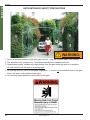
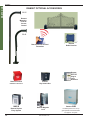
FOR CLASS I VEHICULAR GATE OPERATORS
www.ramsetinc.com
TABLE OF CONTENTS
Important Safety Requirements & Instructions …………………………………………….........……. 1
Responsibilities of Installers and Technicians …………………………………………………………. 2
Important Safety Requirements by UL Standards …………………………………….………………. 3
Classes of Vehicular Gate Operators/Recommended Electrical Connection …..………………….. 4
General Specifications ………………………………………………………………………………….... 5
Installation Specifications ………………………………………………………………………………... 6
Hookup Electrical Power - Gate Travel Adjustment …………………………………………………... 7
Standard Installation in Closed and Opened Position ……………………………………………..…. 8
Compact Installation in Closed and Opened Position ………………………………………………… 9
Sensor Installation ………………………………………………………………………………………..10
Pushbutton Controls & Master/Slave Installation ……………………………………………………..11
Dip Switch Configuration ……………………………………………………………………………. 12-13
Terminal Strip Connections for Optional Accessories …...............………………………………14-15
Ramset "Intelligate" Control Board ………………………………………………………....…………. 16
Wire Board Connections ………………………………………………………………………………... 17
Exploded View ……………………………………………………………………………………….…... 18
Bill of Materials ………………………………………………………………………………………. 19-20
Troubleshooting Table …………………………………………………………………………….......... 21
Gate Entrance Safety Precautions ……………………………………………………………………. 22
Important Information for The Homeowner………………………………..........……………………. 23
Optional Ramset Accessories …………………………………………………………………………. 24
Do not install this gate operator if you do not have experience or appropriate
WARNING: training with gate operators.
IMPORTANT SAFETY REQUIREMENTS & INSTRUCTIONS
WARNING To reduce the risk of injury or death:
1. READ AND FOLLOW ALL INSTRUCTIONS.
2. Never let children operate or play with gate controls.
Keep the remote control away from children.
3. Always keep people and objects away from the gate.
NO ONE SHOULD CROSS THE PATH OF THE MOVING
GATE.
4. Test the Vehicular Gate Operator monthly. The gate
MUST reverse on contact with a rigid object or stop
when an object activates the non-contact sensors.
After adjusting the limit of travel, retest the Vehicular
Gate Operator. Failure to adjust and retest the
Vehicular Gate Operator properly can increase the
risk of injury or death.
5. Use the Emergency Release only when power switch
or circuit breaker has been turned off. Using the Emergency Release during a power failure can be a
hazard if power is abruptly restored.
6. KEEP GATES PROPERLY MAINTAINED. Read the
Owner’s Manual. Have a qualified service person
make repairs to gate hardware.
7. The entrance is for vehicles only. Pedestrians must
use separate entrance.
8. SAVE THESE INSTRUCTIONS.
006.04.24
www.ramsetinc.com
1
RAM 30 UL
RAMSET
RAM 30 UL
RAMSET
RESPONSIBILITIES OF INSTALLERS AND TECHNICIANS
INSTALLATION:
• READ AND UNDERSTAND THE INSTRUCTION MANUAL BEFORE ATTEMPTING
ANY INSTALLATION.
• DO NOT EXCEED THE EQUIPMENT SPECIFICATIONS.
• INSURE A SAFE AND PROPER INSTALLATION.
• INSTALL THIS EQUIPMENT IN ACCORDANCE WITH THE UL 325 SPECIFICATIONS.
• MAKE SURE TO ELIMINATE ANY PINCH POINTS EXISTING ON THE INSTALLATION.
(ie. ROLLERS, ARMS…etc.)
SAFETY DEVICES:
• REMOVE OR PROTECT ALL PINCH POINTS FROM GATE OPERATORS ARMS.
• MAKE SURE EVERY INSTALLATION HAS A MINIMUM OF ONE SAFETY DEVICE
(SUCH AS A PHOTOELECTRIC EYE OR LOOP DETECTOR).
• CHECK THE E.R.D. SENSITIVITY.
• MAKE SURE THAT ALL AREAS AROUND THE GATE ARE SAFE AND SECURE.
(SUCH AS THE FRONT, REAR, AND TRAVEL AREA).
COMMUNICATE WITH THE END-USER
• INSTRUCT THE END USER ON HOW TO SAFELY OPERATE ALL FUNCTIONS
OF THE OPERATOR.
• INSTRUCT THE END-USER ON HOW TO SAFELY USE THE EMERGENCY
RELEASE.
• CLEARLY LABEL AND IDENTIFY THE CIRCUIT BREAKER FOR THE OPERATOR.
• SHOW THE END-USER THE LOCATION OF THE CIRCUIT BREAKER FOR THE
OPERATOR.
• THOROUGHLY EXPLAIN ANY AND ALL WARRANTIES ASSOCIATED WITH THE
OPERATOR AND INSTALLATION.
• KEEP A COPY OF EACH MANUAL HANDY FOR FUTURE REFERENCES.
• PROVIDE THE END-USER WITH THE "HOME OWNERS MANUAL PACKET"
(INCLUDED WITH EVERY OPERATOR).
2
www.ramsetinc.com
IMPORTANT SAFETY REQUIREMENTS BY UL STANDARDS
Prior to installation of a Ramset gate operator,
the following must be observed:
(per UL 325.51.8.4).
a) Install the vehicular gate operator only when:
1) The Vehicular Gate Operator is appropriate
for the construction of the gate and the usage
class of the gate.
2) All openings of a horizontal slide gate are
guarded or screened from the bottom of the
gate to a minimum of 4 feet (1.2 m.) above
the ground to prevent a 2 1/4 inch (57.15 mm.)
diameter sphere from passing through the
openings anywhere in the gate, and in that
portion of the adjacent fence that the gate
covers in the open position.
3) All exposed pinch points are eliminated or
guarded.
4) Guarding is supplied for exposed rollers.
b) The Vehicular Gate Operator is intended for
installation only on gates used for vehicles.
Pedestrians must be supplied a separate
access opening.
c) The gate must be installed in a location so that
enough clearance is supplied between the gate
and adjacent structures when opening and closing to reduce the risk of entrapment. Swinging
gates shall not open into public access areas.
d) The gate must be properly installed and work
freely in both directions prior to the installation of
the Vehicular Gate Operator. Do not over-tighten the
operator clutch to compensate for a damaged
gate.
e) Controls must be far enough from the gate so
that the user is prevented from coming in contact
with the gate while operating the controls.
Controls intended to be used to reset a Vehicular
Gate Operator after 2 sequential activations of
the entrapment protection device or devices
must be located in the line-of-sight of the gate.
Outdoor or easily accessible controls shall have
a security feature to prevent unauthorized use.
f) All warning signs and placards must be installed
where visible in the area of the gate.
g) For Vehicular Gate Operators utilizing a noncontact sensor in accordance with 30A.1.1 Type
B1 non-contact sensor (photo electric sensor or
the equivalent).
1) See instructions on the placement of noncontact sensors for each type of application.
2) Care shall be exercised to reduce the risk of
nuisance tripping, such as when a vehicle,
trips the sensor while the gate is still
moving, and.
3) One or more non-contact sensors shall be
located where the risk of entrapment or
obstruction exists, such as the perimeter
reachable by a moving gate or barrier.
h) For a Vehicular Gate Operator utilizing a contact
sensor in accordance with 30A.1.1
1) One or more contact sensors shall be located
at the leading edge, trailing edge, and postmounted both inside and outside of a vehicular
horizontal slide gate.
2) One or more contact sensors shall be located
at the bottom edge of a vehicular vertical lift
gate.
3) One or more contact sensors shall be located
at the pinch point of a vehicular vertical pivot
gate.
4) A hardwired contact sensor shall be located
and its wiring arranged so that the communication between the sensor and the vehicular
gate operator is not subjected to mechanical
damage.
5) A wireless contact sensor such as one that
transmits radio frequency (RF) signals to the
vehicular gate operator for entrapment protection functions shall be located where the
transmission of the signals are not obstructed
or impeded by building structures, natural
landscaping or similar obstruction. A wireless contact sensor shall function under the
intended end-use conditions.
www.ramsetinc.com
3
RAM 30 UL
RAMSET
RAM 30 UL
RAMSET
CLASSES OF VEHICULAR GATE OPERATORS
Vehicular horizontal slide-gate operator (or system) - A vehicular gate operator (or system) that controls
a gate which slides in a horizontal direction that is intended for use for vehicular entrance or exit to a drive,
parking lot, or the like.
Vehicular swing-gate operator (or system) - A vehicular gate operator (or system) that controls a gate
which swings in an arc in a horizontal plane that is intended for use for vehicular entrance or exit to a drive,
parking lot or the like.
Residential vehicular gate operator-Class I - A vehicular gate operator (or system) intended for use at a
home of one-to four single family dwellings, or a garage or parking area associated there with.
Commercial/general access vehicular gate operator-Class II - A vehicular gate operator (or system) intended for use in a commercial location or building such as a multi-family housing unit (five or
more single family units), hotels, garages, retail stores, or other buildings serving the general public.
Industrial/limited access vehicular gate operator-Class III - A vehicular gate operator (or system) intended
for use in an industrial location or building such as a factory or loading dock area or other locations not
intended to service the general public.
Restricted access vehicular gate operator-Class IV - A vehicular gate operator (or system) intended for
use in a guarded industrial location or building such as an airport security area or other restricted access
locations not servicing the general public, in which unauthorized access is prevented via supervision by
security personnel.
RECOMMENDED ELECTRICAL CONNECTION
For a single operator use a 3 wire, 120 VAC or 220 VAC electrical circuit with a 15 amp independent circuit
breaker. Loop wires and low voltage wires, should use separated conduit!
NOTE: Always consult and follow all local building and electrical codes prior to installation!
RECOMMENDED WIRE GAUGE
MAXIMUM CONDUIT DISTANCE IN FEET
USING COPPER WIRE BY WIRE SIZE
AMPERE
INPUT POWER
120V Single Phase
4
MOTOR HP
RUN
START
14ga.
12ga.
10ga.
8ga.
1/2
4.7
5.0
up to 100'
100-350'
350-650'
800'
www.ramsetinc.com
RAM 30 UL
RAMSET
RAM 30 UL
GENERAL SPECIFICATIONS:
Heavy Duty Torque-limiter:
Absorbs high impacts on gates to minimize
damage on gear reducer.
Maximum Gate Size & Weight: 12' @ 400 lbs.
Gate Traveling Speed: Approx. 90º opening in 16 sec.
Cycles: 30 per hour. / Shipping: 75 lbs.
Application: Residential.
Heavy Duty Worm Gear:
Lubricated by oil bath gives smooth and quiet
operation.
WARNING: Do not exceed the specifications.
Electric Motor:
1/2 hp 120 VAC 5.2 amp 1625 rpm 50/60Hz
continuous duty with high speed ball bearings
and resettable overload button.
I M P O R TA N T:
Always shut power Off before attempting to use the
emergency release.
POWER FAILURE RELEASE:.
Capacitor:
Aerovox 65µƒ 240V 50/60Hz protected
S 1000AFC.
Heavy Duty Pillow Block Assembly:
High speed sealed ball bearings.
1. Remove knob from top cap
2. Loose knob from clamp arm.
Limit Switches:
For accurate gate stop settings.
Ramset "Intelligate" Control Board
It is controlled by a programmable microprocessor
that reds and precisely executes all functions.
3. Slightly bend the arms at
the elbow and secure the gate
from free-movement to relieve the
pressure on the operator from the
gate.
4. Carefully lift off the clamp
release and arm.
5. Push gate open.
20"
13 1/ 2 "
13 1/ 2 "
Chassis: 3/16" Hot rolled metal. Cold/zinc plated to inhibit corrosion.
Cover: High-impact resistant charcoal grey polyethylene.
www.ramsetinc.com
5
RAM 30 UL
RAMSET
INSTALLATION SPECIFICATIONS
CONCRETE PAD CONSTRUCTION:
Dimensions given for the pad are based on soil
bearing shear of 2000 P.S.F. These figures may
have to be adjusted depending on local soil
conditions.
1. Construct form for mounting pad according to
dimensions shown in Figure 1 and 2.
STANDARD INSTALLATION
Gates from: 4' to 12' [ 23" ]
COMPACT INSTALLATION
Gates up to 10' [ 17" ]
2. Locate mounting pad according to dimensions
given in illustration.
3. Level top edge of form.
4. Set reinforcing bars and wire mesh.
5. Allow pad to cure for 48 hours, and remove
forms.
6. Note: conduits 6" above concrete pad.
Figure 1
Figure 2
6
www.ramsetinc.com
RAM 30 UL
RAMSET
HOOKUP ELECTRICAL POWER
Figure 3
Outlet
Leads
NOTE: Hookup your electrical 15 amp wires
direct to outlet.
GATE TRAVEL ADJUSTMENT
Figure 4
Cam
Slams
Limit
Switches
Gate travel is adjusted by loosening the
limit Cams and positioning them until
proper gate travel has been achieved.
www.ramsetinc.com
7
RAM 30 UL
RAMSET
STANDARD INSTALLATION FOR GATES FROM 4' TO 12' IN LENGTH
Figure 5
SPACE REQUIRED FOR A STANDARD GATE IN THE OPEN POSITION
Figure 6
8
www.ramsetinc.com
RAM 30 UL
RAMSET
COMPACT INSTALLATION FOR GATES UP TO 10' IN LENGTH
Figure 7
MINIMUM SPACE REQUIRED FOR COMPACT INSTALLATION
20" minimum space
required between, open
gate and wall for this
compact installation.
Figure 8
www.ramsetinc.com
9
RAM 30 UL
RAMSET
SENSOR INSTALLATION
Ramset Gate Operators should not be installed without non-contact sensing devices such as
Loop Detectors, photo electric sensors or the equivalent.
WARNING:
A non-contact sensor (photoelectric sensor or equivalent) and a contact sensor (edge
device or equivalent) is required on each individual installation to comply with UL325.
Reversing Loops on the ground floor, prevents gate from closing when vehicle is in loop area.
Exit Loops on the ground floor, opens gate when vehicle crosses loop area.
Photoelectric Safety Sensor (Photo Eye) prevents the gate from closing when any object interrupts
the beam.
Figure 9
10
www.ramsetinc.com
PUSHBUTTON CONTROLS
Three pushbuttons are located under the dip switches for operation of the gate (see Figure 11). The opening,
stop and closing buttons can be utilized to set limit switches and verify proper system operation when
installing or servicing an operator.
Opening
Pressing this button will cause the gate to open.
L.E.D.’s light up when Opening,
Closing or Stopped
Stop
Pressing this button will cause the gate to
stop moving.
Figure 10
"Intelligate" Control Board
Closing
Pressing this button will cause the gate to close.
Reset E.R.D. Board
Push all three pushbuttons for approximately
5 seconds. All three L.E.D.’s should blink.
Figure 11
MASTER / SLAVE INSTALLATION
Set Dip Switch (C8) "Slave Mode" to ON for
slave operator.
(RH) Right Hand operation requires Dip Switch
(C7) "Left/Right" to be ON.
Use jumper
JP7 to JP7
Use 3-stranded, shielded wires
(not supplied) from Master to Slave.
Route low-voltage wires for
Master/Slave in a conduit
separate from power.
Conduit for Power
www.ramsetinc.com
11
RAM 30 UL
RAMSET
RAM 30 UL
RAMSET
DIP SWITCH CONFIGURATION
Figure 12
Dip Switch Up for "ON"
Dip Switch Down for "OFF"
DIP SWITCH "A"
Dip Switch "A" 1, 2 & 3; AUTOMATIC TIMER TO CLOSE GATE
‘0’ is “OFF”
Switch
(Constant warning when gate is in motion).
‘1’ is “ON”
1 2 3
Gate Open Duration:
Sw.
1 1 1
60 seconds
OFF No effect.
1 1 0
45 seconds
1 0 1
30 seconds
1 0 0
15 seconds
0 1 1
10 seconds
0 1 0
05 seconds
0 0 1
00 seconds
0 0 0
Disabled - command required to close
ON
Function:
Triggers the prewarn relay to maintain a closed
contact while gate is in motion.
Dip Switch "B" 4 & 5; “ADDRESS 1 & ADDRESS 0”
Up to four separate entrance addresses are available for
installations with multiple entrance or exit locations.
Master and slave gates that work together should be set to
the same address. (Side gates use the address setup)
Sw. 4 5 Function:
Dip Switch "A" 4; 1/2 HP E.R.D.
Sw.
Dip Switch "B" 3; “CONSTANT WARN”
0 0 Default - Entrance 1
Function:
0 1 Entrance 2
OFF Most sensitive or when using 3/4 hp motor.
1 0 Entrance 3
ON
Stronger (Less sensitive) E.R.D. for 1/2 hp motors.
DIP SWITCH "B"
Dip Switch "B" 6; Not in use at this time.
Leave in the ‘Off’ position.
Dip Switch "B" 1; Not in use at this time.
Leave in the ‘Off’ position.
Dip Switch "B" 7; Not in use at this time.
Leave in the ‘Off’ position.
Dip Switch "B" 2; “PREWARN”
Sw.
Pre Warning Relay:
Dip Switch "B" 8; 3/4 HP E.R.D.
OFF Normal Operation
ON
12
1 1 Entrance 4
Adds a 3-second delay before the gate moves in
any direction. During This 3 second delay the
PREWARN Relay maintains a closed contact.
Sw.
Function:
OFF
Most sensitive or when using a 1/2 hp motors.
ON
Stronger (Less sensitive) E.R.D. for 3/4 hp motors.
www.ramsetinc.com
RAM 30 UL
RAMSET
DIP SWITCH "C"
Dip Switch "C" 7; “LEFT / RIGHT”
Dip Switch "C" 1; “SECURE CLOSE”
Sw.
Sw.
Function:
OFF Normal Operation
ON
When power is lost, then regained, control board
checks status of the gate. If open and safety
devices are cleared, gate will close automatically.
Function:
OFF Left hand installations - All operators come factory
set for left hand operation.
ON
Right hand installations - Reverses motor & limit
switches without moving any wires.
Dip Switch "C" 8; “SLAVE MODE” Master/Slave configuration
WARNING:
Sw.
When installing or servicing an operator, make sure switch
"C" 1 is ‘Off’. If switch "C" 1 is ‘On’, the gate will move
when power is applied and severe injury may occur.
Function:
OFF Master mode - single gate operation. All peripheral
devices are to be connected to the master operator.
ON
Dip Switch "C" 2; Not in use at this time.
Slave mode - used to synchronize operation between
two gates. Commands are received from the master
through a 3-wire, shielded cable.
(Not provided with unit).
Leave in the ‘Off’ position.
Dip Switch "C" 3; “RADIO CYCLE”
Sw.
Function:
OFF Normal Operation - gate only opens and closes on
the limit switches. If the gate is in travel then it will
always open.
ON
Cycle mode - gate opens and closes on the limit
switches, but if in travel, then it will stop with a first
command and reverse with a second command.
Dip Switch "C" 4; “ONE PASS”
Sw.
Function:
OFF Normal Operation - fully opens and closes
ON
One pass mode - The gate will open until “the reversing loop” is initially activated and then cleared, the
gate will then close. If the “reversing loop” is then
activated again, before the gate is fully closed, the
gate will stop until the “reversing loop” is cleared, then
continue to close.
Dip Switch "C" 5; “CLOSE DELAY”
One second delay on the closing of the gate.
Dip Switch "C" 6; “OPEN DELAY”
One second delay on the opening of the gate.
www.ramsetinc.com
13
RAM 30 UL
RAMSET
TERMINAL STRIP CONNECTION FOR OPTIONAL ACCESSORIES
Figure 13
14
www.ramsetinc.com
Terminal # 1 - COMMON:
Low voltage common.
sound for 6 minutes and the control board will not
accept any commands. After the 6 minutes the
24 VDC is removed from the alarm connection
and the board resets to normal operation.
Terminal # 2 - REV LOOP:
Used with safety edge mounted on post or back
of gate.
TERMINAL STRIP CONNECTIONS
Stops the gate from closing. If the gate is open,
it holds the gate open. If the gate is closing, it
stops and reopens the gate. If the gate is closed,
the gate will remain closed. The function can be
altered with Dip Switch "C" 4 (see “Dip Switch
Configuration”). Used with loop detectors, photo
eyes, safety edges on front side of gate etc.
Becomes active with a closed contact to common.
Terminal # 9 and 10 - LIMIT 1 & LIMIT 2:
Direction depends on Dip Switch "C" 7 (See “Dip
Switch Configuration”). Stops the motor from
moving in one direction. These wires are preset
in factory and should not be moved. Becomes
active with a closed contact to common.
Terminal # 11 and 12 - COMMON:
Low voltage common.
Terminal # 3 - CLOSE:
Closes the gate. Used with three button stations
or pushbuttons. Becomes active with a closed
contact to common.
Terminal # 13 - +24 VAC:
Provides 24 VAC for peripheral accessories.
Terminal # 14 and 15 - MAG (-) & MAG (+):
Terminal # 4 - FIREBOX:
Opens the gate. Used with fire department key
switches & controls. Opens with closed contact
to common. Closes immediately when closed
contact on common is removed.
Supplies 24 VDC to a Magnetic Lock when the
gate is closing or closed. If gate is opening or
opened, then no power is supplied. Leave open
if not used.
Terminal # 16 - M BRAKE:
Terminal # 5 - EXIT:
Opens the gate. Used with loop detectors, photo
eyes, keypads, phone entry systems, three-button stations…etc. Becomes active with a closed
contact to common.
Used ONLY on the Ram 50 Operator. If while the
gate is closed someone or something tries to
manually open the gate without a proper signal
(keypad, exit loop, radio signal…), the motor will
lock up for 6 minutes. After the 6 minutes, the
operator will then secure close the gate.
Terminal # 6 - PHANTOM:
Keeps the gate open when the open limit switch
is activated. Used with loop detectors. Becomes
active with a closed contact to common.
Terminal # 7 - RADIO:
Operation depends on dip switch "C" 3 (See “Dip
Switch Configuration”). Used with an RF receiver
or pushbutton. Becomes active with a closed
contact to common.
Terminal # 17 and 18 - MOTOR 1 & MOTOR 2:
Supplies power to the motor. Direction depends
on Dip Switch "C" 7 (see “Dip Switch Configuration”). These wires are preset and connected in
the factory and should not be moved.
Terminal # 19 and 20 - AC HOT & NEUTRAL:
110 VAC or 220 VAC to power the operator.
Voltage is predetermined at factory and cannot
be changed by the installer or technician.
Terminal # 8 - EDGE:
When triggered the gate will stop. The gate
will remain stopped until the detector is cleared.
Once the detector is cleared, the operator will
resume normal operation. If triggered twice
before reaching a limit switch, the alarm will
www.ramsetinc.com
15
RAM 30 UL
RAMSET
RAM 30 UL
RAMSET
RAMSET “INTELLIGATE” CONTROL BOARD
Introduction:
sary board modifications between 110 VAC and
Ramset’s “Intelligate” Control Board works
220 VAC single-phase applications.
with Sliding, Swinging and Overhead vehicular
functions of the Control Board are: 0 - 60 seconds
gate operators. It is controlled by a program-
automatic close timer, self adjusting E.R.D. with low
mable microprocessor that reads and precisely
and high setting, constant warning, prewarning,
executes all functions of the Control Board.
secure close, one pass, open & close delay, left/right
The Control Board is powered by a separate
hand operation, plug-in loop detectors and RS485
mounted 18 VAC transformer. This allows no neces-
three wire master/slave connection.
Some of the
Figure 14
JP10
JP9
JP3
JP7
JP6
16
www.ramsetinc.com
JP2
RAM 30 UL
RAMSET
WIRE BOARD CONNECTIONS
JP9 - Input Power:
1,2) 24 VAC power.
Connection from external transformer to
power Control Board.
JP3 - 3 Button:
1) Close
2) Stop 3) Open 4) Common
Used with a 3-button station to open,
stop, and close the gate. The open and close are
normally open connections and the stop is a normally closed connection, remove jumper wire when
connecting 3 button station. Common and stop are
also used with a photo eye used to protect the backplane of the operators.
JP7 - Master/Slave plug:
1) A
2) B
3) Common
4) 5 VDC
5) 24 VAC.
Used to synchronize the operation between two
gates. A three-wire, Shielded cable is needed to run
from the A, B, & Common (JP7) of the master P.C.B.
to the A, B, & Common (JP7) of the slave P.C.B.
JP6 - Battery back-up plug:
1) A
2) B
3) Common
JP2 - Relay Connections:
1)
2)
3)
4)
24 VDC.
24 VAC
5 VDC
Fully Open-N.O.
5) Relay Common
6) Fully Closed-N.C.
7-8) Constant/Prewarn
9-10) E.R.D. Alarm.
If E.R.D. is triggered twice before reaching a
limit, 24 VDC is supplied to sound an alarm (included
with operator).
Fully Open N.O. (works with relay common) Relay rated at 125 VAC, 2 amps. Normally open
connection. Open contact occurs until the open
limit is triggered. When the open limit is
triggered, a closed contact occurs.
Relay Common - Relay rated at 125 VAC, 2 amps.
The common of the Fully Closed N.C. relay and
the Fully Open N.O. relay.
Fully Closed N.C. (works with relay common) Relay rated at 125 VAC, 2 amps. Normally
closed connection. Closed contact occurs until
the closed limit is triggered. When the closed
limit is triggered, an open contact occurs.
4) 5 VDC
5) 24 VAC.
Use this plug when using optional battery
back-up system, Ramset Keypad.
JP10 - Loop Inputs:
1-2) Reverse 3-4) Exit 5-6) Phantom
Use with ILD-24 Loop wires
should be connected to this plug.
JP4, JP5 & JP8 - Reverse, Exit & Phantom
Sensor:
Used with the Ramset ILD-24 plug-in loop detector.
The Loop wires should be connected into the
“LOOP INPUTS” plug.
www.ramsetinc.com
17
RAM 30 UL
RAMSET
RAM 30 UL
Exploded View
57
Figure 15
8
46
62
74
17 2
3
23
28
27
20
15
25
16
26
52
33
68
10 8
11 4
18 4
17
67
32
26
22
21
47
61 2
42
24
17
19
65
50
18
5
40
29
51
56
61
61
53
61
61
53
39
61
19 2
41
38
39
3
63
41
64
55
10 2
1
84
38
9
12 4
66
31
58 2
14
61
4
44
43 2
36
82
37
45
94
70
42
10 4
34
14 2
2
84
35
69
6
59
60 2
49
13 2
48
30
14 4
18
www.ramsetinc.com
RAM 30 UL
RAMSET
BILL OF MATERIAL FOR: RAM 30 UL
ITEM
PART #
PART DESCRIPTION
RAM 30 UL
1
50-027
Gear Reducer Size 40 60:1
1
2
50-039
20 Pin Edge Connector
1
3
50-050
40 b 12 7/8" Sprocket
1
4
50-069
Limit Switch 00h-3
2
5
50-084
# 40 Drive Chain
1
6
50-091
# 6 x 1" Machine Screw
2
7
50-092
3/8-16 x 1 1/2" Hex Head Bolt
4
8
50-095
5/16-18 x 3/4" Hex Head Bolt
13
9
50-096
5/16" Lock Washer
8
10
50-097
5/16" Flat Washer
14
11
50-103
3/8-18 Hex Head Lock Nut
4
12
50-104
5/16" Hex Head Nut
4
13
50-105
# 6 Hex Head Nut
2
14
50-107
# 6 x 3/8" Machine Screw
8
15
50-110
1/2-14 x 2 1/2" Hex Head Bolt
3
16
50-111
1/2-14 x 3 1/2" Hex Head Bolt
1
17
50-112
1/2" Flat Washer
4
18
50-113
1/2-14 Nylon Lock Nut
5
19
50-114
1/4-20 Socket Head Screw
4
20
50-115
Polyethylene Cup Cover
1
21
50-117
1" x 2" x 32" Rectangular Metal Tube
1
22
50-118
1" x 2" x 42" Rectangular Metal Tube
1
23
50-126
Channel
1
24
50-127
2 1/2" Torque Limited Arbor
1
25
50-128
2 1/2" Torque Limited Washer
1
26
50-129
2 1/2" Torque Limited Friction Disc
2
27
50-130
2 1/2" Torque Limited Tension Washer
1
28
50-131
1-3/4" Torque Limited Nut
1
29
50-149
Access Door Lock
1
30
50-151
Warning Sign for Gate
2
31
50-168
Horn Alarm
1
32
50-172
3 1 1/2" Clamp Release
1
33
50-181
Torque Limited Bushing
1
34
50-183
Limited Switch Bracket
1
35
50-200
1/2 Hp 115 VAC Electric Motor
1
36
50-205
Capacitor
1
37
50-215
Rocker Switch
1
38
50-247
3/4" Sealed Ball Bearing
2
39
50-253
3/4" Collard Shaft
2
40
50-263
1/4" x 5" Key Way
1
41
50-265
3/16" x 3/4" Key Way
2
42
50-275
1 1/2" UHMW Spacer
1
43
50-295
#8 Self-Tap Sheet Metal Screw
2
44
50-299
Radio Receiver Terminal
1
www.ramsetinc.com
19
RAM 30 UL
RAMSET
BILL OF MATERIAL FOR: RAM 30 UL
20
ITEM
PART #
PART DESCRIPTION
RAM 30 UL
45
50-304
120/240 Intelligate Transformer
1
46
50-337
1/2" x 1-1/2" Hex Head Bolt
1
47
50-339
1" x 2" Plastic Cap
2
48
50-401
10 Ga Heavy Duty Metal Chassis
1
49
50-402
Board Lexan Glass Cover
1
50
50-403
Polyethylene Cover
1
51
50-404
3/4" x 10" Limit Switch Shaft
1
52
50-405
40A27 Sprocket
1
53
50-406
3/4" Limit Switch Cam
2
54
50-407
1/2" x 1" Cast Iron Pulley
2
55
50-408
6" Aluminum Pulley
1
56
50-409
4L V Belt #250
1
57
50-419
1/4" x 1 1/2" x 10" Ext. Gate Bracket
1
58
50-529
#6 x 2" Machine Screw
2
59
50-511
120 VAC Double Outlet
1
60
50-526
#6 x 1/4" Machine Screw
2
61
50-539
5/16" Socket Head Screw
9
62
50-546
Internal Gate Bracket Swing Arm
1
63
50-559
Access Door Frame
1
64
50-560
Access Door
1
65
50-563
1 1/2" x 1 1/2" x 3/4" Sq. Pivot
1
66
50-564
1/2" x 1 1/2" Iron Pulley
1
67
50-565
5/16" x 1 1/2" Knob
1
68
50-566
5/16" x 1/2" Knob
1
69
50-569
Instruction Manual
1
70
50-777
Intelligate Control Board
1
www.ramsetinc.com
RAMSET
CONDITION
RAM 30 UL
TROUBLESHOOTING TABLE
SOLUTION
POSSIBLE CAUSES
NO LIGHTS ARE 'ON'
1. Circuit breaker popped.
2. 1/2 amp. fuse blown.
3. Power supply damaged on
control Board.
1. Reset circuit breaker.
2. Replace 1/2 amp. fuse.
3. Return Control Board for repair.
GATE MOVES A COUPLE
OF FEET AND THEN
REVERSES
1. E.R.D. too sensitive.
1. A) for 1/2 hp motors: turn dip switch
"A" 4 'On'.
"EXIT" L.E.D. IS ALWAYS
'ON'
1. Faulty accessory connected
to the "Exit".
1. Disconnect all accessories, including
plug-ins, using the "Exit" input.
If problem persist, contact Ramset.
"REV LOOP" L.E.D. ALWAYS
'ON'
1. Faulty accessory connected
to the "Rev Loop".
1. Disconnect all accessories, including
plug-ins, using the "Rev Loop" input.
If problem persist, contact Ramset.
"RADIO" L.E.D. ALWAYS
'ON'
1. Stuck button on Transmitter
1. Check all transmitters.
2. Remove receiver.
If problem persist, contact Ramset.
B) for 3/4 hp motors: turn dip switch
"B" 8 'On'.
2. Faulty Receiver.
GATE DOESN'T OPEN
1. Radio L.E.D. 'On'.
2. 10 amp. fuse blown.
3. Opening accessory not functioning.
1. See above symptoms/solutions.
2. Check/replace 10 amp. fuse.
3. Check/replace opening accessory.
GATE DOESN'T CLOSE
1. No lights are 'On'.
2. Exit, Rev Loop, Radio L.E.D. 'On'.
3. 10 amp. fuse blown.
4. Thermal/overload button
popped on motor.
1.
2.
3.
4.
GATE DOESN'T CLOSE
AUTOMATICALLY
1. Dip switches "A" 1-3 are all
'Off'.
1. Set dip switches "A" 1-3 for auto
close.
2. Turn off dip switches "A" 1-3, then
turn the appropriate switches back
'On'.
2. Dip switch not on all the way.
GATE AUTOMATICALLY
OPENS, BUT DOESN'T
AUTOMATICALLY CLOSE
RADIO/RECEIVER HAS
NO RANGE
See above symptoms/solutions.
See above symptoms/solutions.
Check/replace 10 amp. fuse.
Reset thermal/overload button on the
back of the motor.
1. Motor direction wrong.
1. Turn on dip switch "C" 7 (left/right).
1. Signal blocked.
1. Make sure antenna is in proper position & not shorted to chassis.
2. May need to change to long range
receiver.
2. Area not suitable for type of
Receiver.
www.ramsetinc.com
21
RAM 30 UL
RAMSET
GATE ENTRANCE SAFETY PRECAUTIONS
WARNING:
1. Never let children operate or play with gate controls. Keep the controls away from children.
2. The entrance is for vehicles only. Pedestrians should use a separate entrance.
3. Always keep people, children and objects away from the gate while the gate is in operation.
No one should cross the area of a moving gate.
4. All opening devices, (such as a keypad, cardreader…), should not be installed close to the gate,
where the gate could possibly cause injury.
5. Use warning signs attached on both sides of the gate.
22
www.ramsetinc.com
RAM 30 UL
Opening the way…
Important information for the homeowner
Ask your technician about all the features of our new Ramset operator.
Safety devices, such as reverse loops, phantom loops, photo eyes, or miller edges must be
installed on your gate before the operator may be used. Ask your technician which safety devices best
suit your safety needs.
Read your warranty certificate and fill out your warranty extension card. Return the warranty
card, via certified mail, to Ramset within 90 days of purchase:
Ramset Automatic Gate Services, Inc.
9116 De Garmo Ave.
Sun Valley, CA. 91352
Never let children operate or play with gate controls. Keep the controls away from children.
The entrance is for vehicles only. Pedestrians should use a separate entrance.
Always keep people, children and objects away from the gate while the gate is in operation. No
one should cross the area of a moving gate.
Use the emergency release only when the gate is not moving. Make sure when using the foot
release or hand crank, the circuit breaker for the operator is turned off.
Have the technician give you a demonstration of how to use the emergency release.
Keep gates properly maintained. Have a qualified gate technician service the gate operator and
gate hardware every six months to a year. This includes checking of safety devices, E.R.D. and
battery back up systems.
Warning signs must be placed on every gate in a highly visible area.
To reset the audible alarm on the gate operator you must turn the circuit breaker for the operator
off for approximately 10 seconds, then back on. An exterior switch or button can also be
installed on the operator to shut off the audible alarm.
Always keep a good relationship with your technician and keep his or her number handy
for future maintenance or emergencies.
Ramset wishes to thank you for trusting us
to meet your gate operator needs.
www.ramsetinc.com
23
RAM 30 UL
RAMSET
RAMSET OPTIONAL ACCESSORIES
20-05
Ramset
Mounting
Post for
Access
Control
50-40
Ramset Remote Control
Transmitter
Ramset
Radio Receiver
Ramset
ILD-24
Plug-in
Loop
Detectors
Ramset Fire Box
EMERGENCY ENTRY BOX
RKLE
Ramset Keyless
Entry System
24
Ramset
Key Switch Box
Ramset Magnetic
Lock
www.ramsetinc.com
Ramset
RPI
Provides power for a 1/2 hp
gate operator and accessories.
For approx. 50 cycles.
www.ramsetinc.com


![PCR-258-Tip Kit Manual [110125]](http://vs1.manualzilla.com/store/data/005777628_1-f6da4e9104aae97408b67d66533e329f-150x150.png)