1
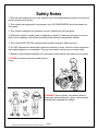
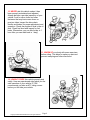
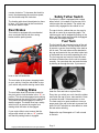
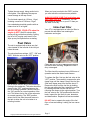
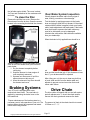
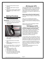
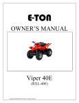
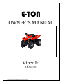
E-TON
OWNER’S MANUAL
Viper Jr.
(RXL-40)
Copyright ©2008-2009 ETON America, all rights reserved.
Copyright ©2008-2009 ETON America, all rights reserved.
Important Notices
READ and UNDERSTAND this owner’s manual
Both the operator and the adult supervisor should completely read and understand this
owner’s manual before operating this vehicle. This owner’s manual will instruct you in the safe
operation of the vehicle.
NO Passengers
This vehicle was designed for operation ONLY by the operator, (Driver). The load limit
and seat configuration is designed for the operator ONLY. It is not safe to carry passengers on
the vehicle.
ADULT Supervision and Instruction are REQUIRED.
This vehicle MUST NOT be operated by a youth without Adult supervision and
instructions. Unattended operation without adult supervision could result in injuries. E-TON
recommends that both the operator and the adult supervisor attend an ATV safety instruction
course.
ALWAYS Wear Protective Clothing
While operating this vehicle, the driver must always wear protective clothing. Protective
helmet with face shield, elbow and knee pads, long leg pants, gloves and hard soled boots
should always be worn when operating this vehicle.
OFF ROAD Use ONLY
This vehicle is designed and manufactured for off-road use only. Operation on public
streets, roads or highways is illegal and very dangerous.
OBEY all State and local laws and regulations
Each state and local governing agency has laws and regulations for ATV operations. It
is the owner’s responsibility to know, understand and obey these laws and regulations.
SPEED RESTRICTION Devices
This vehicle is equipped with electronic speed limiting devices. Any attempt to change,
over-ride or bypass these devices may cause dangerous operating conditions.
Copyright ©2008-2009 ETON America, all rights reserved.
Page 1
Table of Contents
Safety notes
Vehicle identification number location
Controls, switches and feature locations
Control feature operations
Engine stop switch
Remote Stop Switch
Throttle lever
Rear Brakes
Parking brake
Safety Tether Switch
Fuel System
Fuel tank
Fuel valve
Inline Fuel Filter
Engine Oil
Tires & Wheels
Tire inspection
Tire pressure
Spark Plug
Air Filter
Braking Systems
Drive Chain
Throttle Lever
Transmission Oil
ATV Break-In Procedure
Pre-Operation Inspection
Starting procedure
Driving
Turning
Parking
10
10
10
10
11
11
12
13
13
13
14
15
15
15
Specifications
Maintenance Schedule
Wiring Diagram
Manufacture’s Warranty
Owner’s notes
15
17
18
19
21
Copyright ©2008-2009 ETON America, all rights reserved.
Page 2
3
6
6
7
7
7
8
8
8
8
9
9
10
Safety Notes
1. Both the adult supervisor and youth operator must fully understand everything in this manual
before operating this vehicle.
2. This vehicle was designed for the operator only. NO PASSENGERS should be allowed on
this vehicle.
3. This vehicle is designed for operation on level, obstacle free off-road areas.
4. Riding this vehicle on public roads or highways is illegal. If it becomes necessary to cross a
public road or highway, the vehicle should be pushed across using extreme caution.
5. This vehicle MUST NOT be operated without adult supervision and instruction.
6. DO NOT operate this vehicle while under the influence of drugs, alcohol or other medication
that impairs judgment or coordination. Doing so can result in serious injury or even death.
7. Maintain a safe distance between your vehicle and other vehicles with whom you are riding.
8. READ the owner’s manual carefully before
riding.
9. ALWAYS wear a helmet, face shield, elbow &
knee pads, hard-soled boots, gloves, and protective
clothing while operating this vehicle.
Copyright ©2008-2009 ETON America, all rights reserved.
Page 3
10. NEVER ride this vehicle unless it has
been properly maintained and adjusted.
Always perform a pre-ride inspection of your
vehicle. Look for wires, bolts and other
fasteners that may have come loose on
previous rides. Inspect the drive chain,
throttle and brakes for proper adjustment and
operation. Check the engine oil level in the oil
tank. Check fuel level and inspect for fuel
leaks. (Remember, you can ride further in 1
hour than you can walk back in 1 day!)
11. WARM UP your body with some exercises
before riding. This helps to make you alert and
prevent cramping and other discomfort.
12. LEARN TO RIDE this vehicle properly and
safely. Have an experienced rider teach you the
safe operation of your vehicle. E-TON
recommends you take an ATV riding course
before you first ride your vehicle.
Copyright ©2008-2009 ETON America, all rights reserved.
Page 4
13. NEVER REFUEL this vehicle when hot. Ask
your adult supervisor to refuel your vehicle.
Gasoline is extremely flammable and will ignite if
spilled on a hot engine or muffler. Never smoke
or expose the fuel to an open flame or spark
while refueling your vehicle. Always refuel your
vehicle in a safe place free of any ignition source.
14. NEVER run the vehicle in an enclosed area. The
exhaust gases from the engine contain CARBON
MONOXIDE which can be fatal if breathed in high
concentrations for an extended time.
15. HOT! The engine and exhaust system on
your vehicle become very hot during normal
operation. Touching these hot surfaces can
cause severe burns. Always assume that your
unit’s engine and exhaust system are HOT
unless you know that they are not.
Copyright ©2008-2009 ETON America, all rights reserved.
Page 5
Vehicle Identification Numbers
Vehicle Identification Number (VIN)
is located at the front of the unit under
the front fender on a plate mounted
between the main frame rails.
Engine serial number
is located on the left-hand side of the
engine on the crankcase housing.
Your VIN RFZ______________ Eng. No. _______________
Controls, Switches & Feature Locations
Locations of controls and features
1. Fuel Tank filler and vent tube
2. Fuel Valve
3. Throttle lever
4. Rear/Parking brake lever
5. Engine stop switch
6. Safety Tether switch
7. Pull Starter
Copyright ©2008-2009 ETON America, all rights reserved.
Page 6
Control feature operations
Engine Stop
Switch
The remote switch has two buttons, a Stop
button which will stop the engine when pressed.
The effective range of the switch is 30 feet
unobstructed.
Once the unit has been stopped with the remote
switch you must press the run button in order for
the unit to be restarted. This action resets the
remote receiver on the unit.
Safety Note: Always test the remote switch
The stop switch is a red colored rocker switch
located on the left-hand handle bar.
before beginning a riding session. The remote
switch is operated by a battery which should be
replaced once a year. You can obtain a
replacement battery at your local department
store.
To start and run the engine, this switch must
be placed in the on, “O”, position.
The vehicle is also equipped with a safety
brake switch which will prevent the engine
from starting until the parking brake is
engaged.
To stop your engine, place the switch to the
stop, “X”, position.
In the stop, “X”, position the ignition system is
grounded preventing the spark plug from
firing.
This switch can also be used as a safety or
emergency stop switch.
Throttle lever
The throttle lever is located on the right-hand
handle bar below the grip. To operate the throttle
lever, place your right thumb on the lever and
press forward to increase your speed. To
decrease your speed, reduce your pressure on
the lever and the spring tension will
automatically reduce your speed.
The travel of the throttle lever is controlled by the
throttle stop bolt.
Remote Stop Switch
The Viper Jr. comes equipped with a remote
Stopt key ring switch.
Copyright ©2008-2009 ETON America, all rights reserved.
As your operator gains more experience, you
can increase the throttle travel to allow for
additional speed to be obtained.
To increase the throttle’s travel, thus increasing
the maximum speed, turn the throttle stop bolt
Page 7
counter clockwise. To decrease the throttle’s
travel, thus decreasing the maximum speed,
turn the throttle stop bolt clockwise.
The throttle cable should be adjusted so there
is 2mm, (1/8”) free travel at the lever before
the throttle starts to open.
Rear Brakes
This vehicle is equipped with a mechanical
drum rear brake that is both the running
brakes and the parking brake.
Safety Tether Switch
The Viper Jr. model is equipped with a safety
tether switch. It is located on at the rear of the
vehicle under the rear fender. The switch cap
must be fully engaged for the vehicle to run.
The cap is tied to a tether that can be worn by
the ride or control by a supervising adult. The
vehicle engine can be stopped by pulling on the
tether until the switch cap becomes disengaged.
This action will stop the engine.
Fuel Tank
The fuel tank fill cap is located on top of the unit
just ahead of the seat. The cap contains a vent
to prevent a vacuum from forming in the tank as
fuel is used. The vent tube must be attached to
the cap and inserted in the vent tube holder hole
of the handle bar cover while operating the unit.
The fuel cap vent and vent tube must be clean
and clear of obstructions for the unit to operate
normally. You can check the vent and vent tube
by blowing air through the tube. If you can not
The brake is controlled by the long brake
lever on the left-handle bar.
The rear brake is the primary stopping brake
on your vehicle. Using the rear brake to stop
your vehicle will prevent steering control loss.
Parking Brake
The rear brake lever has a button located at
the pivot point to lock the brake in the, “O”, on
position. This should be engaged as a parking
brake whenever the vehicle is not in operation.
This feature should be engaged in order to
start the engine. The brake lever has a safety
switch built in to prevent the engine from
starting while the brake is disengaged.
If your engine fails to start, ensure that the
engine stop switch is in the on, “O”, position
and that the parking brake is engaged.
Copyright ©2008-2009 ETON America, all rights reserved.
blow through the vent tube and cap you must
clean the vent and tube or replace them.
Every time you refuel your unit, check the rubber
seal inside the cap for cuts, tears and dirt. Clean
or replace the seal if it becomes worn or torn.
The seal must be in good condition to insure a
proper seal of the cap to the tank to prevent fuel
spills. DO NOT allow dirt or other debris to enter
the tank when refueling.
Replace the cap if damaged or if it will not seal
to the tank.
Page 8
Tighten the cap snugly, being careful not to
over tighten. Over tightening the cap can
cause damage to the cap or seal.
The fuel tank capacity is 4.5 liters, 1.2 gal,
including a reserve of 0.8 liters, 0.2 gal.
When you have to switch to the “RES” position
you must refuel the unit as soon as possible.
ALWAYS CHECK YOUR Fuel level before you
start riding your ATV. Remember: You can
drive further in one hour on your ATV than you
can walk in one day.
Use unleaded automobile gasoline with an
octane level of 91 or higher.
NEVER REFUEL YOUR ATV when the
engine is HOT. Wait 30 minutes after
turning off the unit before refueling. Spilling
fuel on a HOT engine could cause a fire.
Wipe up any fuel spills before re-starting.
Inline Fuel Filter
Your ATV is equipped with an inline fuel filter to
prevent dirt and debris from entering the
carburetor and engine.
Fuel Valve
The unit is equipped with a three way fuel
valve located on the left side of the unit just
below the seat.
The valve has three settings; “OFF”, “ON” and
“RES”. With the valve in the “OFF” position
Check the filter for dirt or damage before each
ride and at each refueling. Replace the filter if
dirty or damaged.
The filter should be replaced every 600 hours of
operation and at the start of each season.
fuel is held in the tank and is prevented from
flowing to the carburetor. The valve should be
placed in the “OFF” position whenever the
unit is not being operated. Place the valve in
the “ON” position for normal operation of the
unit. This allows fuel to flow to the carburetor
for normal operating. The “RES” position
allows fuel to flow from the small reserve in
the tank to allow the unit to be taken to a
refueling location.
Copyright ©2008-2009 ETON America, all rights reserved.
To replace the filter, first turn the fuel valve to the
“OFF” position. Then carefully compress the wire
clamp rings until the clamp is free of the fuel line.
Slide each clamp away from the filter about ¾”.
Remove the filter from the fuel line by holding
the line and pulling the filter. Install the new filter
by inserting the filter into the fuel line and
returning the clamps to the original position. Turn
the fuel valve to the “ON” position and check for
leaks. Inspect the fuel lines for cuts, abrasions
and deterioration. Replace fuel lines as needed.
DO NOT start or operate the engine if the fuel
filter or lines are leaking. Leaking fuel can cause
a fire.
Page 9
Engine Oil
2 Cycle Engine
Your ATV uses 2 cycle oil to lubricate the
engine. The oil is mix with the fuel prior to
refueling the unit. Use a synthetic 2 cycle oil
and mix at a 50:1 ratio with the fuel.
(About 2.5oz to a gallon)
Never run the engine with straight fuel as
sever engine damage will occur requiring
the engine to have to be rebuilt or
replaced.
Tires and Wheels
Tire & Wheel inspection
It is important to inspect your tires and wheels
for damage and wear before each riding
Check your tire pressure before each riding
session and at each refueling operation. Always
check the pressure when the tires are cool. Use
the tire pressure gauge that came with your ATV
to check the tire pressure.
Tire Pressure
Recommended tire pressure is:
7psi Maximum (Hot after riding)
2psi Minimum (Cold before riding)
Wheel Nut torque 24-30 N/m (18-22 lb/ft)
Spark Plug
Replace spark plug at the beginning of each
season with a replacement plug
NGK BPM6Y/NGK
Disconnect spark plug wire.
Clean dirt from around spark plug base with
brush or air.
Remove spark plug with spark plug wrench.
Set the spark plug gap on the new plug to 0.023”
Install the new by plug screwing it in finger tight
and then use the plug wrench to screw the plug
in another ½ turn.
Inspect the spark plug wire for cuts, nicks or
other damage. Replace as needed.
Air Filter
session. Inspect each tire for cuts, tears and
punctures. Inspect the wheel rim for dents
and separation of the wheel from the tire bead.
Replace any tire or wheel found to be
damaged.
Operating your ATV with damaged tires or
wheels is dangerous. Damaged tires or
wheels can result in a sudden loss of tire
pressure and control which could result in
injuries.
Copyright ©2008-2009 ETON America, all rights reserved.
Air Filter Maintenance
To maintain the highest performance from your
engine and to reduce excessive wear that could
cause engine failure, the engine requires a
continuous flow of clean air. Air is taken into the
engine through an air filter to clean the air prior to
mixing it with fuel and oil in the carburetor.
During normal operation the filter accumulates
dirt from the air and will need to be cleaned to
maintain the proper air flow. The filter should be
cleaned every 30 days, more often if you ride in
a dusty or dirty environment and the element
should be replaced every year.
The air filter box is located on the left side of the
engine. To access the air filter you must remove
Page 10
the left side engine shield. The cover is about
3x4” box and is attached to the crankcase with
two bolts
To clean the filter
Remove the air filter box cover. Remove the
filter element from the air box. Clean the screen
located in the mounting box behind the element.
Rear Brake System Inspection
Visually inspect the brake cable for any signs of
wear, kinking, corrosion or other damage.
Test the brake by applying pressure to the brake
lever and trying to push the unit forward. If the wheel
rotates while the brake is applied, check your brake
cable, brake adjustment and brake pads. If the brake
lever feels hard to squeeze the brake cable may
need to be lubricated or may be damaged.
Lubricate the cable with a cable lubricant available
from your dealership.
When the brake is fully applied there should be a
Wash the element in a non-flammable solvent
such as Air-Filter cleaner from your local auto
parts dealer.
1. Dry the element completely before
continuing.
2. Soak the element in clean engine oil
until completely saturated.
3. Squeeze out the excess oil until the
element does not drip any oil.
4. Allow the element to dry then reinstall
the element and cover.
minimum clearance of ½” of clearance between the
lever and the handle bar grip. If this clearance is less
that ½” your brakes should be adjusted
After riding your unit, be sure to clean any build up
of mud, sand and dirt from the brake cable and
adjuster to prevent rust and corrosion that could
cause cable failure.
Braking Systems
Your ATV unit is equipped with a rear
mechanical drum brake. The rear brake is
applied by squeezing the brake lever on the
left-handle bar.
Proper maintenance of the brake system is a
necessary part of safe operation of your unit. The
brake systems should be inspected and tested
before each riding session.
Copyright ©2008-2009 ETON America, all rights reserved.
Drive Chain
The drive chain will stretch with use and will require
periodic adjustments. To check the chain tension,
remove the chain guard and measure the slack.
The amount of slack in the chain should not exceed
10-20mm or ¼” - ½”.
Page 11
Inspect the drive and axle sprockets for worn,
damaged or broken teeth. Replace as needed.
Inspect the chain links for damaged, worn or
loose rivets. Repair or replace as needed.
Throttle Lever
The throttle lever is located beside the righthandlebar grip and is operated by using the righthand thumb. The lever is spring loaded and will
return to the idle position when you remove your
Chain Slack Adjustment
thumb from the lever. To accelerate the unit, simply
Loosen the axle position lock bolt slightly and turn press the lever forward to open the throttle slide in
the chain adjuster nut to take up the excess slack the carburetor. To slow the unit, reduce the pressure
in the chain. Once the chain has been adjusted
on the lever or remove your thumb and the throttle
to the proper tension retighten the axle position
will return to the idle position automatically.
locking bolt.
The chain should be kept well lubricated to
prevent excess wear and premature failure. We
recommend that you lubricate the chain every 15
hours of operation, or more frequently if needed,
with a high quality chain lubricant.
Adjusting the throttle
The cable should be adjusted to allow for ⅛” free
travel before the throttle engages the carburetor
throttle slide. To adjust the cable’s free travel, loosen
the locking nut of the cable adjuster, and turn the
adjuster wheel until there is ⅛” free travel in the
lever. Tighten the locking nut to secure the adjusting
ring.
The speed of the unit can be adjusted by adjusting
the throttle stop screw to limit throttle travel.
Loosen the throttle stop screw locking nut and turn
the throttle stop screw clockwise to reduce the
Copyright ©2008-2009 ETON America, all rights reserved.
Page 12
throttle travel thus reducing the maximum
speed of the unit. Turning the stop screw
counter clockwise will increase the throttle
travel thus increasing the maximum speed of
the unit. Tighten the stop screw locking nut
when the desired throttle travel has been
established.
NOTE: Your unit includes an electronic speed
control that is set to limit the maximum speed of
the unit to the standards set by the CPSC for
the age of the rider for which the unit was
designed for.
Changing Transmission Oil
ATV Break-In procedures
Your ATV requires a break-In period just as with
all other internal combustion engines. This
period allows the engine parts to seat and wear
properly without undue strain which can cause
premature failure.
1. For the first two weeks of operation do
not run your ATV at full throttle for
extended periods of time.
2. You should only fill the fuel tank with a
premix of fuel and synthetic 2cycle oil at
a 50:1 ratio (Approximately 2.5oz of oil
per each gallon of fuel). Use unleaded
fuel only with an octane rating of at least
89.
3. Do not operate the unit at more than 85%
of maximum speed.
4. Do not over rev the engine.
5. Use light braking pressure to allow the
brake shoes to seat to the drum.
Pre-Operation Inspection
procedure
1. Place an oil catch pan under the unit
directly below the transmission box.
2. Remove the transmission box drain
plug located on the bottom of the
transmission box on the underside of
the unit.
3. Remove the transmission box fill hole
plug locate on top of the transmission
box near the oil tank bracket on the
left hand side of the unit.
4. Allow the oil to drain completely (15-30
min).
5. Reinstall the drain plug and tighten.
Torque to 7-10lbf-ft
6. Fill the transmission box with 70cc of
SAE 80-90 gear oil.
7. Reinstall the fill hole plug finger tight.
8. Dispose of used oil at a proper
recycling station as required by law.
Copyright ©2008-2009 ETON America, all rights reserved.
The following procedure must be performed
before each operating session.
Checking your ATV takes only a few minutes
and may save you from serious injuries and
costly repairs.
1. Check engine fuel level.
2. Check brake & brake cable operations.
3. Check tire condition and pressure.
4. Check drive chain condition and slack.
5. Check throttle operation and free play
adjustment.
6. Check engine stop switch for proper
operation.
7. Check steering system. Look for free and
smooth operation. Check all fastening
hardware.
8. Check all nuts, bolts and other fasteners
for loose conditions.
9. Inspect unit for any broken or damaged
parts.
10. Check all indictor lights and switches for
proper operation.
Page 13
11. Test remote Stop switch for proper
operation.
12. Test safety tether switch for proper
operation.
13. Insure you are wearing proper clothing
and protective gear. Helmet, Gloves
Pads etc.
Starting Procedure
The following procedure must be followed
each time you start your unit.
Park the unit on a level surface and lock the
parking brake.
1. Turn the fuel valve to the “ON” position.
2. Turn the engine stop switch to the
“ON” position.
Driving your ATV
Your ATV should only be driven in an area that
is designated for this use. Insure that the area is
free of obstacles and other dangers that could
cause a loss of control. Check with your local
authorities for any regulations regarding the use
of your ATV.
Always keep your feet on the footrests and your
hands on the handle bar grips while operating
your ATV. Doing so will give you the best control
of the unit.
Start your ATV by following the starting
procedure above and allow the engine a few
minutes to warm up before releasing the parking
brake.
Start the unit by slowly increasing the throttle
until the unit begins moving.
Turning your ATV
Learning to turn your ATV requires you to learn
to shift your weight and control the throttle to
allow the rear wheels to turn properly. When
making a turn, the wheels on the outside of the
turn must travel a wider radius and thus a
greater distance than the inside wheels of the
turn. Since the rear axle does not permit a
different rate of rotation, it is not enough to
merely steer your ATV into the turn.
3. Set the carburetor choke to closed,
“ON”, position by pushing the choke
lever up fully.
4. Apply slight pressure to the throttle
lever.
5. Pull the starter handle sharply on the
left-handle bar.
Your unit should start within 1 or 2 pulls of the
starter handle. If the unit fails to start check
the following.
1. Engine stop switch is “ON”.
2. Parking Brake Locked “ON”.
3. Tether switch is fully inserted.
4. If you used the remote switch to stop
the unit you must press the run button
to reset the receiver stop switch.
Copyright ©2008-2009 ETON America, all rights reserved.
To turn properly, steer in the direction of the turn
and lean your body to the inside of the turn while
supporting your weight on the outer footrest. Use
the throttle to maintain power throughout the turn.
If you do not use this turning technique the unit
will have a tendency to continue in a straight line.
If this occurs, release the throttle lever to allow
the unit to stop.
Avoid braking or accelerating until you have
regained directional control.
Page 14
3. Set the engine stop switch to “OFF”
position.
4. Engage the parking brake locking button.
5. Turn the fuel valve to the “OFF” position.
6. Remove the ignition key to prevent
unauthorized use or theft of your ATV.
Parking Your ATV
1. Always park your ATV on a level
surface.
2. Turn the ignition key to the “OFF’”
position to stop the engine.
2004 Viper Jr. RXL-40 Specifications
Viper Jr. (RXL-40)
Engine
Type
Displacement
Bore / Stroke
Compression
Power
Two cycle air cooled pre mix fuel/oil
41.5cc
φ40.0 * 33.0mm
6.6 : 1
2.2ps @ 7000rpm
Transmission
Type
Single Speed Centrifugal Clutch
Chassis
Overall Length
Overall Width
Overall High
Wheel Base
Dry Weight
1120mm / 44.0"
630mm / 24.8"
727mm / 28.6"
768mm / 30.2"
64kg / 134lbs
Suspension
Front
Rear
A-Arms Dual Shocks
Swing Arm / Single Shock
Brakes
Front
Rear
N/.A
Mechanical Drum
Tires
Front
Rear
Front
Tire Pressure
Rear
Min
Max
Min
Max
145/70-6
145/70-6
2psi / 0.14kg/cm2 (Cold)
7psi / 0.49kg/cm2 (Cold)
2psi / 0.14kg/cm2 (Cold)
7psi / 0.49kg/cm2 (Cold)
Wheels
Bolt Pattern
Direct attach
Carburetor
Make/Size
Main Jet
Pilot Jet
Idle Speed
HC 16mm (Manual Coke)
64mm
18mm
Idle 2500rpm
Copyright ©2008-2009 ETON America, all rights reserved.
Page 15
Sprockets
Front
Rear
Chain
14 teeth
36 teeth
#420
Battery
N/A
Fluids
Fuel
Engine Oil
Transmission
Type
Volume
Type
Unleaded Gasoline 89 octane
3.5 liters / 0.9 gal
High grade synthetic 2 cycle oil
Volume
Type
Volume
Pre Mix 50 : 1
SAE 80/90 weight
70cc / 2.4oz
Spark Plug
NGK
Nipendenso
Champion
Electrode Gap
Maximum Rider Weight
Minimum Rider Age
BPM6Y/NGK
W22MP-U
CJ7Y (Not Recommended)
0.6-0.7mm / 0.023"
36.3kg / 80lbs
6 years
Copyright ©2008-2009 ETON America, all rights reserved.
Page 16
Maintenance Schedule
First week
Every 30 Days
Every Year
I
Fuel Lines
Throttle Operation
Air Filter
Fuel Filter
Spark Plug
Drive Chain
Brake Shoes
Brake System
Bolts, Nuts & Fasteners
Wheels
I
I
C
I, L
R
R
R
I
I, L
I
I
I
I
I
I
I
I
Inspect as part
of pre-ride
inspection
I
Steering system
Every 6 months
Suspension System
Transmission Oil
Choke
Spark Arrester
Battery
Notes
Replace Fuel & Vent
Lines every 2 years
Inspect as part
of pre-ride
inspection
Inspect as part
of pre-ride
inspection
Inspect as part
of pre-ride
inspection
Inspect as part
of pre-ride
inspection
I
R or 100 hrs
I
C every 100 hrs R every 200 Hours
I, C
I = Inspect, Clean, Adjust, Lubricate or Replace as needed
C= Clean
L = Lubricate
R = Replace
Owners Maintenance Records
Maintenance Preformed
Copyright ©2008-2009 ETON America, all rights reserved.
Date
Page 17
Preformed By
Copyright ©2008-2009 ETON America, all rights reserved.
Page 18
ETON AMERICA, LLC.
LIMITED VEHICLE WARRANTY
ETON America warrants all new ETON vehicles sold by authorized Eton Dealers to be free
from defects in materials and workmanship, subject to the following exclusions and
limitations. New vehicles sold by an authorized dealer to original retail consumers are covered
by this policy for a period of six (6) months from the date of delivery. There is no mileage
limitation.
Vehicles used in rental service or for certain commercial purposes are specifically excluded
from this policy. (Check with your dealer for warranty application.)
Items and conditions that are specifically excluded from this warranty program are;
1. Damage caused by accidents, misuse, negligence, improper vehicle operation.
2. Any modification or alteration to any standard specifications or equipment.
3. Any repairs made by an unauthorized dealer or service firm.
4. Use of non-ETON genuine parts for repairs or alteration to standard specifications.
5. Damage caused by failure to perform factory scheduled service maintenance.
6. Damage which occurs as a result of improper storage.
7. Damage caused by the use of improper fuel or lubricants, and/or failure to use proper
oil/gas mixture on two stroke models.
The following normal wear parts are specifically excluded from warranty coverage:
1. Rubber parts
2. Tires
3. Belts
4. Brake linings
5. Normal wear item
6. Brake parts
7. Cables
8. Filters
9. Spark plugs
10. Bulbs
11. Batteries
12. Sprockets
13. External springs
14. Seat and hand grips.
Copyright ©2008-2009 ETON America, all rights reserved.
Page 19
ETON AMERICA, LLC.
LIMITED VEHICLE WARRANTY
Scheduled maintenance service is the responsibility of the owner during and after the warranty
period. In the event of a failure or required repair, the owner should take vehicle to an
authorized dealer for repair without undue delay and within a maximum of thirty, (30), days of
the occurrence of the problem. All eligible warranty repairs must be made at any authorized
dealer’s normal place of business. Any transportation costs, or other expenses which may
occur in order to obtain warranty service, are the responsibility of the owner. All eligible
repairs covered under this warranty will be paid to the servicing dealer only, by ETON
America, and no additional payments shall be made for authorized warranty repairs.
Dealer and/or ETON America are not responsible for loss of use, other damage or
inconvenience due to warranty repairs. It is the customer/buyer’s responsibility to review with
the selling dealer the pre-delivery service schedule to assure machine is properly serviced prior
to delivery acceptance. It is recommended that the buyer take a test ride to familiarize
themselves with the machine and to make certain the unit is in proper operating condition. The
dealer is responsible for checking and performing all items on the “set-up and pre-delivery
checklist” prior to delivery to the customer.
This warranty is valid at any authorized ETON Dealer in the United States only. In the event
you experience any problem obtaining prompt service, contact ETON America, customer
service department for assistance. Always consult first with your selling dealer and/or service
personnel for assistance with any service work or repairs. In the event you have a problem
obtaining service send your name, address, and vehicle identification number to Eton America
for assistance.
The above stated policy is the only policy offered and backed by ETON America, and no other
organization or individual is authorized to make or offer any different arrangements. Some
states prohibit certain limitations or conditions or do not allow exclusions or limitations. You
may be eligible for additional consideration, so check with your local dealer or appropriate
state agency for assistance. Rights vary from state to state, and you may have other rights not
offered in this warranty.
ETON America warrants all new vehicles comply with applicable US regulations.
Copyright ©2008-2009 ETON America, all rights reserved.
Page 20
Owner’s Notes:
Copyright ©2008-2009 ETON America, all rights reserved.
Page 21
Copyright ©2008-2009 ETON America, all rights reserved.
Page 22