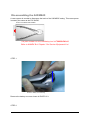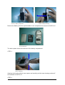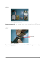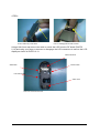
1
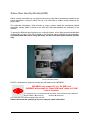
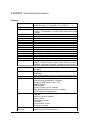
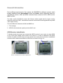
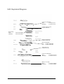
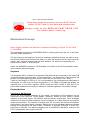
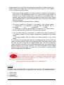
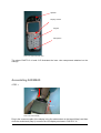
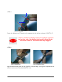
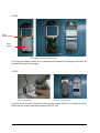
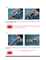
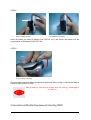
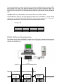
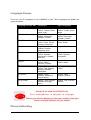
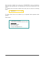
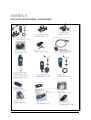
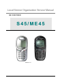
Local Service Organization Service Manual BE INSPIRED S45/ME45 Version 1.0 i S I E M E N S C O M M U N I C AT I O N S L I M I T E D Table of Contents CHAPTER 1 GPRS (General Packet Radio Services) 1 Subscriber Identity Module 2 ANNEX A Exploded View – Accessories 31 CHAPTER 2 Level 2 Service Guide 3 Introduction 3 S45/ME45 Technical Information 4 Technical Data 5 Original Accessories 6 General Information 8 S45 Exploded Diagram 9 ME45 Exploded Diagram 10 Mechanical Concept 11 Power Supply & Integrated Charging 13 Disassembling the S45/ME45 17 Assembling the S45/ME45 22 International Mobile Equipment Identity 27 Mobile Software Programming 28 Language Groups 29 Phone Unblocking 30 Our Innovation Shapes the Future ii Chapter 1 GPRS (General Packet Radio Services) Overview. G PRS is a new non-voice value added services that allows information to be sent and received across a GSM mobile telephone network. It supplements today’s Circuit Switched Data (CSD) and Short Message Services (SMS). GPRS involves overlaying a packet based air interface on the existing circuit switched GSM network. This gives the option to use a packet-based data service. The information is split into separated but related “packets” before being transmitted and reassembled at the receiving end. Theoretically, maximum speeds of up to 171.2 kilobits per second (kbps) are achievable with GPRS using all eight timeslots at the same time. This is about 3 times as fast as the data transmission speed possible over today’s fixed telecommunications networks and 10 times as fast as current Circuit Switched Data services on GSM networks. Example: Cell with 1 Frequency channel: 1 physical channel for signalling, 4 physical channels for Circuit switched and 3 physical channels for Packet switched Figure1. Example of GPRS data transmission iii Subscriber Identity Module(SIM) SIM is a smart card which has a computer and memory chip that is permanently installed in the mobile equipment. It comes in either the size of a credit card or smaller version known as the plug-in SIM. The subscriber information, which includes a unique number called the International Mobile Subscriber Identity (IMSI) is stored in the SIM card. SIM card identifies the subscriber to the network. To protect the SIM card from improper use, a security feature, a four digits personal identification number(PIN), is built in. The PIN is stored in the card and can be changed by the subscriber. Any deactivated SIM, due to wrong PIN entry, can be re-activated by the network operator only. PHOTO.1 SIM CARD ACCESS PHOTO 1 illustrates the steps for inserting the SIM card into the S45/ME45. S45/ME45 only support 3V or 1.8V SIM card. S45/ME45 will prompt for “Insert SIM card” when a 5V SIM card is inserted. For Singapore Only: To distinguish between Phase 1(5V) and Phase 2(3V) SIM card. Singtel: Phase 1 Fxxxxxxxx Phase 2 GAxxxxxxx M1: at the back of the SIM card label Phase 2 & 16K. Please check with the operator(s) in your country for detail information. Chapter Level 2 Service Guide 2 Introduction This chapter serves as a guideline to help the respective service personnel in the repairing of S45/ME45 mobile phones up to Level 2. The repair for S45 and ME45 are identical unless otherwise noted, therefore the description herein is confined to S45 only. S45/ME45 is the first dual band(GSM 900 and GSM 1800) with GPRS capability handset. All repairs have to be carried out in an environment set up according to ESD regulations defined in international standards. S45/ME45 Technical Information Features System/Standards Speech Codec Display Standby Time Talk Time Battery Capacity Silent Alert Weight Volume Dimension SIM Type Antenna Phonebook Address book Dialing Voice Dial SMS Intelligent Typing Ringer Clock SAT Data Services Organizer Digital Voice Recorder / DUAL BAND EGSM900 / GSM 1800 GSM PHASE 2 / PHASE 2+ & GPRS Triple Rate (HR/FR/EFR) High resolution graphical display with 7 lines x 16 characters (101 x 80 pixels) with extreme high contrast Up to 300h (with standard Li-Ion battery) Up to 6h (with standard Li-Ion battery) LiIon 850mAh Integrated vibrator Approx. 93 g, including standard battery Approx. 69 cm3 109 x 46 x 20mm (L x W x H) Plug in (1.8/3V) Integrated Up to 250 entries (Dependent on SIM card) Up to 300 addresses 10 redial numbers; 10 missed calls, 10 last incoming calls Voice Dialing / Voice Commands & Voice Memo MO, MT, CB Intelligent Typing (T9) in following languages: English, German, French, Italian, Dutch, Danish, Finnish, Swedish, Norwegian, Spanish, Portuguese and Chinese 38 ringer tones plus 4 individual ringer melodies; melody composer Clock / Alarm / Date / World Clock Stopwatch Date & Time Stamp for last 10 missed and incoming calls SIM Application Toolkit Class 3 Mobile Internet Access (WAP 1.2) Data Services @ 9.6kbps & 14.4kbps Fax @ 14.4kbps & Fax class 2, G3 Built-in Modem IrDA Interface Remote Control (via AT Cellular) Data Download OTA (ringer tones, bitmap) Flexible Memory Management Organizer functionality with Calendar Alarm list (up to 50 entries) Address book Send business card Calculator Appointments / Tasks Currency Converter Microsoft Outlook synchronisation Screensaver with PIN protection Dictaphone Exciting games Available colour variants: Sapphire Blue, Diamond Silver (vary country by country) High speed data transfer, speedy internet access using GPRS Built-in dictionary Technical Data •GSM Phase 2+ specification •Dual band EGSM specification : 880MHz ~ 960MHz GSM 1800 specification : 1710MHz ~ 1880MHz •Triple rate vocoder (Half rate, full rate and enhanced full rate) •Power Output: Class 4 (2 Watt) for EGSM and Class 1 (1 Watt) for GSM 1800 •User Interface: High resolution graphical display •Battery: Standard 850mAh Li-Ion •GPRS data transmission • SMS/Phonebook Management remote control conforms to ETSI GSM 07.05 and 07.07 • FAC code (digit 7 and 8 of the IMEI-number): Leipzig Shanghai Bocholt Kamp-Lintfort Pandrup • ▪ -> 32 and following -> 37 and following -> 41 and following -> 51 and following -> 70 and following ISO date code (Manufacturing date): Format: K1 Code Year K 1998 L 1999 M 2000 N 2001 P 2002 R 2003 S 2004 T 2005 U 2006 V 2007 W 2008 X 2009 Month January February March April May June July August September October November December Code 1 2 3 4 5 6 7 8 9 O N D Example ▪ Phones : J5 = May 1997, M3 = March 2000 Batteries and accessories : 9825 Year and Calendar Week Original Accessories • 850 mAh Li-Ion battery (standard) L36880-N4501-A100 • Car cradle standard L36880-N4501-A102 • Car cradle with antenna cap L36880-N4501-A103 • Belt Clip L36880-N4501-A105 • Plug-In power Sup Euro S45 L36280-Z4-C351 • Plug-In power Sup UK S45 L36280-Z4-C352 • Desktop Charger L36880-N4501-A101 • Car Charger L36880-N4001-A123 • Leather Holster L36880-N4001-A154 • Belt Case L36880-N4801-A116 • Neoprene Case L36880-N4001-A155 • Grip Case L36880-N4501-A132 • Loop Case L36880-N4501-A133 • Leather Case L36880-N4501-A131 • Basic Car Pack L36880-N4501-A107 • Car Kit Comfort L36880-N4501-A104 • Car Kit Portable L36880-N3015-A117 • Car Kit Professional Voice II L36880-N4501-A109 • Car Kit GPService Pilot L36880-N4501-A116 • Soft Data Link 5.0 L36880-N4501-A115 • Headset with PTT key L36880-N4001-A123 • Retractable Headset L36880-N4001-A160 • Car data adapter L36880-N4501-A134 • Data Cable Ll36880-N3015-A148 • Multi Media Card 32MB L36880-N4501-A137 Colour Variants ( May vary by country ) S45/6618 • Sapphire Blue • Diamond Silver ME45 • Pebble Grey • Safari Grey Standard Package for S45/ME45 Phone Charger Battery Cover Battery (no laser label) Accessory leaflet User Manual Mini CD-ROM Data cable Mini CD-ROM (capacity 129MB) contains: PC-Sync software, GPRS driver, User Manual, Accessories, Product demonstration General Information Due to different requirements of the markets, the S45/ME45 has different variants, which broadly classified under International version and Asian version. Marketing name for international version is S45 and ME45, whereas Asian version for S45 is 6618 and for ME45 is 3618. The Asian version (6618/3618) comes with Chinese strokes keypad with the Upper housing without the silk print of “S45”. International version will comes with normal keypad with the printed “S45” Upper housing. The main differences between the S45 and ME45 are: 1. The housings 2. ME45 is shock and water splash proof and S45 is not. GPRS Services Indentification To identify whether the phone has a located the GPRS services in your region, the sign GPRS on top of the phone display will be shown as in Picture 2. In order to attached to the GPRS services, the phone must be camp-on to the network once and virtual connection is established and there will be dotted lines beside the GPRS icon as shown in Picture 2.1. PHOTO 2 S45 GPRS service located on Singtel network PHOTO 2.1 S45 GPRS service attached S45 Exploded Diagram Upper Case Shell S45 Silver L36158-A56-A1 Dark Blue L36158-A56-A2 Cushion (Display) S45 L36158-A56-C32 Keypad S45 Silver Dark Blue L36158-A56-B600 L36158-A56-B601 Display Module S45 L36851-Z1508-A80 RF Control Board S45 L36880-A4500-B10 6618 L36880-A4500-B33 Vibra-Alert Unit L36453-Z5-C109 Lower Case Shell S45 Silver L36158-A56-A210 Dark Blue L36158-A56-A211 Battery Cover S45 Silver L36158-A56-B500 Dark Blue L36158-A56-B501 FIGURE 2 S45 EXPLODED DIAGRAM. ME45 Exploded Diagram Upper Case Shell ME45 Grey-Beige L36158-A55-A11 Grey-Black L36158-A55-A7 Cushion (Display) ME45 L36158-A55-C32 PCB for Keypad L36880-Q4595-A2 RF Control Board ME45 L36880-Q4600-B10 3618 L36880-Q4600-B33 Vibra-Alert Unit L36453-Z5-C109 Lower Case Shell ME45 Grey-Beige L36158-A55-A215 Grey-Black L36158-A55-A213 Figure 2.1 ME45 EXPLODED DIAGRAM Please take note that the number(s) used here IS NOT the part number, DO NOT used it in your spare parts purchase order. Always refer to the SERVICE PART PRICE LIST for spare parts ordering. Mechanical Concept Note: All part numbers are referred to mechanical drawing in Figure 2.2 for S45 & 2.3.for ME45 The mechanical concept of the S35/ME45 differs in various points from the one of the other Siemens mobile telephones. The first thing you will experience is how the housing is locked No screws are used to keep the housing closed even internal of the phone To open the housing, which is kept closed by catches only, a special opening tool has been defined. For details on disassembly tool please refer to Photo 2. in this chapter. Inside, the S45/ME45 consists of 2 PCB boards; on of which is the RF board and the other is the interface with the Keypad. Keyboard The Keyboard will be realised via a separate PCB which will be connected to the main PCB via board-to-board connector with 12 interconnections. The illumination of the keypads will be done via high-brightness LEDs (colour: amber 590 nm, driven by 5 mA / LED). Target for the number of LEDs is 4. If it is not possible to get a homogenious illumination of the keypad, the LED count must be increased to 6. The LEDs for keypad and display are supplied from a 2.9V linear regulator (REG1) inside the ASIC. Unlike in P35 there is no pulse-width-modulation necessary to maintain a constant brightness over battery voltage. Display Modules Overview of HW Structure Due to the LCD-controller shortage in the market, four different LCD-controllers can be connected to the K45-PCB. Three (Hitachi, Samsung, Rohm) do have nearly a similar interface to the power supply, the EGOLD+ and the passive components. Thus, all display modules from various module suppliers can be connected to a single interface by using the mentioned controllers. The interface is realised by a ZIF connector with 28 interconnections. Unfortunately, the fourth display controller (Epson type) has a completely different interface pinning as compared to the three others. Therefore, a separate PCB with a 26-pin ZIFconnector is essential. The different displays can be identified by hardware coding on the FPC in combination with resistors on PCB. The displays will be shipped as complete modules from the suppliers. The design consists of the LCD-cell with a Tape Chip Carrier foil (TCP) and the lightguide. The LEDs for the backlight will be placed on the K45 PCB. The display controllers will be driven with a supply voltage of VDD = 2.65V. For the display module the 4 side-shooter LEDs are mounted on the K45 PCB. The LED colour is amber with a typical wavelength of 590nm. The maximum current per LED will be about 5mA. Different LED types are under evaluation. The luminance is targeted to be ≈1.5 cd/ m² with homogeneity fluctuations of max. ≈25%. The luminance will be comparable to the C25 backlight. The S45 Backlight will be better than the S35. The Display module is connected to the board by a flexible cable which is inserted into a socket connector. In case the display is defective electrically or mechanically it can be exchanged easily. In opposite to the MMI board of other phones (e.g. S6 and E10) the Speaker/Receiver is not soldered to the board, but is mechanically fixed on to the Upper housing and electrically connected to the board by the Speaker’s spring. To be able to do measurements on and software update of the telephone, an adapter cable between Molex- and Lumberg connector will be available. See photos in Additional Tools of Chapter 3. S45/ME45 comes with an integrated antenna and it is built-in to the back of the lower housing. The dust protection frame and the display window are included in the display module. IrDA Low-Power infrared data interface, compatible to “IrDA - Infrared Data Association; Serial Infrared Physical Layer Specification, Version 1.3”, supporting transmission rates up to 115.2kbps (slow IRDA). As a Low-Power-Device, the infrared data interface has a transmission range of - 20cm to other Low-Power-Devices and - 30cm to Standard-Devices The viewing angle is +/-15° (resulting in 30° viewing cone). The transmitting diode fulfils the requirements of IEC825-1 Class 1M Eye-Safety. SIM SIM cards with supply voltages of 1.8V and 3V are supported. Vibration Motor The vibration motor is mounted in the lower case. The electrical connection to the PCB is realised with pressure contacts. Power Supply and Integrated Charging Overview of HW Structure All the important functions for the power supply of the phone are carried out by the supply ASIC. The POWER-pin of the I/O-Connector is for charging the battery with an external power supply. For accessories which provide a variable charge current, the current will be set via a further pin SB (current byte) (e.g. S25 chargers corresponding to CarKits etc.). The standard K45 power supply is unregulated and therefore does not react to the SB signal, but the SB signal will still be used to distinguish the various power connections. The following restrictions must be observed: • The phone cannot be operated without battery inserted. • The phone will be damaged if the battery is inserted with wrong polarity (the mechanics of the phone prevent the battery from being put in the wrong way round. The electrics system assumes that the battery has been inserted correctly. This must be ensured via suitable QA measures). Inside the LiIon-battery-pack is a protection-circuit, consisting of a small elecronic circuit and a polyfuse, to prevent the battery from overcharging, deep discharge and overcurrent Battery As a standard battery an Li-Ion battery with a nominal capacity of 840mAh@1 CA, 830mAh @GSM 2.0/0.2A will be used. Charging Concept The battery is charged in the unit itself. The hardware and software is designed for Li-Ion with 4.2V technology. Charging is started as soon as the phone is connected to an external charger. If the phone is not switched on, then charging shall take place in the background (the customer can see this via the “Charge” symbol in the display). During normal use the phone is being charged (restrictions: see below). Charging is enabled via an MOS switch in the phone. This MOS switch closes the circuit for the external charger to the battery. The processor takes over the control of this switch depending on the charge level of the battery, whereby a disable function in the STVASIC hardware can override/interrupt the charging in the case of overvoltage of the battery (only for NEC Batteries). A third line (SB) shall be used for recognition and control of the S2x charger The SB will be set at a constant 141, which corresponds to a current of 600mA. To distinguish the charging units the C25 charger (150mA charging current) will have a short circuit to the ground, whereas the rapid charger, S25 (1A maximum charging current) will have a high impedance input. The K45 NAG and the P35 NAG will also be fitted with a high impedance input and will therefore be recognised as a rapid charger. The charging software is able to charge the battery with an input current within the range of 350-600mA. If the Charge-Fet is switched off, then no charging current will flow into the battery (exception is trickle charging, see below). For controlling the charging process it is necessary to measure the ambient (phone) temperature and the battery voltage. The temperature sensor will be an NTC resistor with a nominal resistance of 10kΩ at 25°C. The determination of the temperature is achieved via a voltage measurement on a voltage divider in which one component is the NTC. The NTC for the ambient temperature will be in the phone on the main component group. Recognition of the Battery Type The battery code will be an resistor with a resistance of 8.2kΩ up to 56kΩ depending on the manufacturer: 8.2kΩ corresponds to Panasonic 15kΩ corresponds to NEC 27kΩ corresponds to Sanyo 56kΩ not allocated If no resistance is recognised, then the battery will not be charged. Charging Characteristic of Lithium-Ion Cells Li-Ion batteries are charged with a U/I characteristic, i.e. the charging current is regulated in relation to the battery voltage until a minimal charging current has been achieved. The maximum charging current is approx. 600mA, minimum about 100mA. The battery voltage may not exceeds 4.2V ±50mV. The temperature range in which charging of the phone may be started ranges from 5...40°C, and the temperature at which charging takes place is from 0...45°C. Outside this range no charging takes place, the battery only supplies current. Above 50°C the battery no longer supplies any current. Trickle Charging The power supply ASIC is able to charge the battery at voltages below 3.2V without any support from the charge SW. The current will by measured by a shunt resistance and linearly regulated inside the ASIC by means of the external FET driven in it´s active region of the transfer characteristic as a typical linear pass element. The current level during trickle charge for voltages <2.8V is in a range of 20-50mA and in a range of 50-100mA for voltages up to 3.75V. The maximum trickle time is 1 hour. Matching up In order to guarantee a correct working of the charge control, the measurement hardware in the phone must be matched up. The matching up is done by means of a self-test. Restrictions • A battery which has completely run down can not be re-charged quickly because the battery voltage is less than 3.0V and the logics which implements the charge control cannot be operated at this low voltage level. In this case the battery is recharged via trickle-charging. However, the charging symbol cannot be shown in the display because at this time logic supply voltages are not operating. The charging time for this trickle-charging (until the battery can be fast-charged from then on) is in the range of 1 hours. If, within this time, a voltage of 3.2V is exceeded, then the ASIC switches on the mobile and charging continues in the Charge-Only Mode. In some circumstances it can happen that after tricklecharging and the usually initiated switch-on procedure of the mobile, the supply voltage collapses so much that the mobile phone switches off again. In this case trickle charging starts again with a now raised threshhold voltage of 3.75V instead of 3.2V, at maximum for 20 minutes. • A phone with a fully charged Li-Ion battery cannot be supplied in the standby or talk modus in the beginning because any input current would cause an increase in the battery voltage above the maximum permissible value. If, through using the phone, the battery has been run down to the tune of about 95% (estimated value), it can be supplied with current normally and the battery can be re-charged. • The phone cannot be operated without a battery. • The phone would be destroyed if the battery were wrongly poled: ⇒ design-wise it is impossible to wrongly pole the phone. This is prevented by mechanical means. ⇒ electrically, a correctly poled battery is presumed, i.e. correct poling must be guaranteed by suitable QA measures at the supplier • If an unsuitable charger is connected, the mobile phone can be destroyed: ⇒ a charger voltage >15V can destroy resistances or capacitors in the current supply ⇒ a charger voltage >20V can destroy the switch transistor in the current supply. If, in so doing, the transistor fails, then the overvoltage switch-off in the ASIC will cease to function and the ASIC will be destroyed. Then the battery safety switch will come into play. In the case of voltages smaller than 15V and an inoperative current restriction, the battery can be permanently damaged. A protection against grossly negligent use by the customer (e.g. direct connection of the charge contact to the electricity supply in a motor car) is not foreseen. Customer safety will not be affected by this restriction. If the temperature is too high or too low, there is a high probability that the battery is not charged. To enable the charging process again, battery and phone needs to cools down or warm up. Battery replacement is not required. Avoid shorting the battery terminals. Charging The battery can be charged when it is inserted into the phone. The charging process is completely controlled by the mobile. Charging can be done with any of the following accessory: 1. 2. 3. 4. Rapid charger Travel charger Car charger Desktop charger Deep Discharge In case of a deeply discharged battery, the phone can not be turned on and the normal charging process can not be started. In this case, charging the battery is divided into two different steps, which have to be run subsequently: a) Trickle charge Trickle charge mode is automatically started if the battery voltage is below a certain value when the charger is connected to the mobile. This mode is not terminated automatically but has to be terminated by disconnecting the charger. Trickle charge mode has to last minimum until the battery voltage has exceeded a certain level. During trickle charge the charging symbol will not be visible and the telephone can not be turned on. This is because the battery voltage is too low to operate the telephone Action: Insert battery into handset and connect travel charger to the telephone. Wait for appr. 1 hour, then disconnect and reconnect charger. If the battery voltage is high enough again, the charging symbol will come up. If the battery is discharged very deeply, the symbol may not come up and the trickle charge time possibly has to be extended up to 24 hours. b) Normal charge When the battery voltage is above the a.m. value (e.g. by trickle charge) the mobile will start the normal charging mode and show a charging symbol in the display. Action: Connect charger to the telephone. The charging symbol will come up as an indication that the normal charging process has been started by the mobile. Dis-assembling the S45/ME45 A case opener is needed to disengage the latch of the S45/ME45 casing. This case opener is exactly the same as the P35 Series. PHOTO 2.2 S4/ME45 CASE OPENER The part number for this mandatory tool is F30032-P46-A1 Refer to ANNEX B of Chapter 3 for Service Equipment List. STEP 1: Photo 2.3 Battery cover removing Remove the battery cover as shown in PHOTO 2.3. STEP 2: Photo 2.4. Battery compartment Photo 2.5 Battery Removing Remove the Battery from the right handside for the compartment as shown in PHOTO 2.5. Photo 2.6 Backview The above photo shows the backview of the battery compartment STEP 3: Photo 2.7 Opening Opening the housing with the case opener and carefully pull the lower housing section off as illustrated in PHOTO 2.7 STEP 4: Photo 2.8 Lower case removng Remove the lower casing as shown in PHOTO 2.8 STEP 5: Photo 2.9 RF board removing Remove the RF board from the upper casing as illustrated in PHOTO 2.9 STEP 6: Photo 2.10 Keypad PCB and Shield removing Remove the Keypad PCB from the Upper casing and the shielding from the RF Board as illustrated in PHOTO 2.10 STEP 7 Shield latch Photo 2.11 Shielding removing The latch at the side of the shield can be separated from the RF board using a tweezer or finger as illustrated in PHOTO 2.11 STEP 8 Photo 2.12Removing of LCD latches Photo 2..13Disengage the flex cable connector Using a little force and remove the latch to unlock the LCD from the RF board (PHOTO 2.12) and using your finger or tweezer to disengage the LCD connectors to remove the LCD display as shown in PHOTO 2.13 Internal antenna Side button Memo button Infra red window Vibra motor Photo 2.14 Lowercase inner view Speaker Display cushion Keypad Microphone Photo 2.15 Upper case inner view The above PHOTO 2.14 and 2.15 illustrates the inner view components attached on the casings. Assembling S45/ME45 STEP 1: Step 2 Step 1 Photo 2.16 LCD Assembly Plug in the connector cable of the display in the flex cable socket on the board (Step1) and then close the socket latch (Step 2) to secure the LCD display as shown in PHOTO 2.16 STEP 2: Photo 2.17 LCD latches Fasten the display to the RF board and by snapping the side latches as shown in PHOTO 2.17. In order to position the display exactly, the synthetic projection on the lower side of the display frame must be fitted into the hole in the screen lid. The catches must fully engaged. STEP 3: Photo 2.18 Shield placement Photo 2.19 Shield latch snapping Align the shield starting from the side (PHOTO 2.18) and using your finger to snap the latch at the other end to secure the shield (PHOTO 2.19) STEP4: Step 1 Display Cushion Step 2 Keypad Step 3 Keypad PCB Photo 2.20 Keypad and Display cushion assembly First, place the Display cushion on the uppercase and followed by the keypad. Next place the keypad PCB on top of the keypad STEP 5: Photo 2.21 Dust cleaning Photo 2.22 RF board placement Using an air gun or similar equipment to clean the dust residue (PHOTO 2.21) and place the RF board onto the cleaned uppercase as shown (PHOTO 2.22) STEP 6: Photo 2.23 Top assembly Photo 2.24 Bottom assembly Secure the upper and the lowercase shell by snapping the upper part (PHOTO 2.23) and next the lower part (PHOTO 2.24). Precaution must be taken seriously to make sure all components have been in place before assemble the housings! STEP 7: Photo 2.25 Side assembly Photo 2.26 Finish Snap both sides of the casings to secure and to complete the assembly as illustrated in PHOTO 2.25 and 2.26. A L L C A T C H E S M U S T E N G A G E C O M P L E T E L Y ! STEP 8: Photo 2.27 Battery placement Photo 2.28 Battery compartment Insert the battery by sliding it sideway first (PHOTO 2.27) and secure the battery into the compartment as illustrated in (PHOTO 2.28). STEP 9: Step 1 Step 2 Photo 2.29 Battery cover closing Close the battery cover by sliding the lid into the lowercase shown in Step 1 and lock the latch as shown in Step 2 (PHOTO 2.29). The battery contacts must not be dirty, damaged or bent! International Mobile Equipment Identity, IMEI The mobile equipment is uniquely identified by the International Mobile Equipment Identity, IMEI, which consists of 15 digits. Type approval granted to a type of mobile is allocated 6 digits. The final assembly code is used to identify the final assembly plant and is assigned with 2 digits. 6 digits have been allocated for the equipment serial number for manufacturer and the last digit is spare. S45/ME45 IMEI label is accessible by removing the battery cover and the battery. On this IMEI label, Siemens has also includes the date code for production or service, which conforms to the industrial standard DIN EN 60062. The date code comprises of 2 characters: first character denotes the Year and the second character denotes the Month. Example: KD Year 1998 1999 2000 Date Code K L M Month December January February Date Code D 1 2 TABLE 2.1 DIN EN 60062 DATE CODE Mobile Software Programming The software of the mobile, S45/ME45 is loaded from a PC directly. Hardware interconnection between the mobile and the PC is shown in Figure 2.4. The peripherals for the interconnection is defined in the ANNEX page FIGURE 2.4 S45/ME45 SOFTWARE PROGRAMMING SETUP Flow chart 2.1 illustrates the software programming process. Plug in the Boot Adaptor to the PC and Mobile Connect the AC Faulty Check Faulty AC adaptor toBoot the BootAdaptor Adaptor No Yes Power up the PC in DOS environment Check Execute the= H/W setup Correct settings. “Mobile S/W” Yes No S/W Software upgrading in progress Yes Feedback Take noteError of error to Tech. and Supp. repeat Test Mobile END process Dep.again Error ? No Power up Boot Adaptor & Check LED Error ? Yes Ok ? No Ok ? Yes Ok ? FLOWCHART 2.1 SOFTWARE PROGRAMMING. PROCESS No Language Groups There are over 20 languages for the S45/ME45 in total. These languages are divided into groups as follows Language groups K45 Languages Tegic Languages LG 1 International English, German, French, Turkish, Dutch, Italian, Arab English, German, Danish, Norwegian Swedish, Finnish English, German, French, Turkish, Dutch, Italian LG 2 Nordic English, German, Danish, Norwegian, Swedish, Finnish English, German, Czech, Polish LG 3 Eastern Europe English, German, Czech, Polish, Slovak, Russian, Hungarian LG 4 Mediterranean English, Turkish, Greek, Hebrew, Russian, Bulgarian, Arab English, Turkish, Greek LG 5 Iberia English, German, French, Spanish, Portuguese, Catalan, Braz.Port English, German, French, Spanish, Portuguese LG 6 South East Europe English, German, French, Italian, Slovene, Croatian English, German, French, Italian LG 7 South East Asia English, German, French, Thai, Bahasa Malaysia, Bahasa Indonesian English, German, French LG 8 Asia English, Simpl. Chinese, German (if enough place) English, Simpl. Chinese, German LG 9 Taiwan English, Trad. Chinese, German (if enough place) English, Trad. Chinese, German Group 8 & 9 is used for 6618/3618 only. This information is subject to change! Contact your Service Manager for the order number of the right version of mobile software for your market. Phone Unblocking When the phone is disable due to wrong entry of PHONECODE, it can be re-activated by entering the right unblocking code. This unblocking code is derived from the IMEI number of the mobile. The unblocked code, also known as Master Phone Code, has to be entered in the following format: * # 0 0 0 3 * - - - - - - - - # The Master Phone Code can be obtained by your responsible Hotline department within Siemens, Please contact : PT. DIAN GRAHA ELEKTRIKA Jl. Rawa Gelam III no.8 Kawasan Industri Pulo Gadung JAKARTA TIMUR Phone no. 62-21-46826081 Fax no. 62-21-4615080 E-mail [email protected] 1. Internet Solution A password protected homepage where LSO can enter IMEI number of a disable phone. The generated Master Code will then be presented for unblocking purpose. This service is offered to all LSOs. PHOTO 2.30 INTERNET PAGE PHOTO 2.31 INTERNET PAGE: MASTER PHONE CODE Contact your Service Manager for more information regarding setting up of the INTERNET SOLUTION & its installation procedure ANNEX A EXPLOSION VIEW DIAGRAM – ACCESSORIES