1
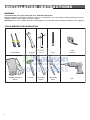
SINGLE CAVITY GAS RANGE
for residential use only
Models:
VEFSGG 365 ..
• INSTALLATION INSTRUCTIONS
IMPORTANT - PLEASE READ AND FOLLOW
IMPORTANT - PLEASE READ AND FOLLOW
✓ Before beginning, please read these instructions completely and carefully.
✓ Do not remove permanently affixed labels, warnings, or plates from the product. This
may void the warranty.
✓ Please observe all local and national codes and ordinances.
✓ Please ensure that this product is properly grounded.
✓ The installer should leave these instructions with the consumer who should retain
for local inspector's use and for future reference.
✓ The electrical plug should always be accessible.
Installation must conform with local codes or in the absence of codes, the National Fuel
Gas Code ANSIZ223.1 - Iatest edition. Electrical installation must be in accordance with the
National Electrical Code, ANSI/NFPA70 - latest edition and/or local codes. IN CANADA:
Installation must be in accordance with the current CAN/CGA-B149.1 National Gas
Installation Code or CAN/CGA-B149.2, Propane Installation Code and/or local codes.
Electrical installation must be in accordance with the current CSA C22.1 Canadian
Electrical Codes Part 1 and/or local codes.
INSTALLATION IN MANUFACTURED (MOBILE) HOME: The installation must conform with
the Manufactured Home Construction and Safety Standard, Title 24 CFR, Part 3280 [formerly the Federal Standard for Mobile Home Construction and Safety, Title 24, HUD (Part
280)] or, when such standard is not applicable, the Standard for Manufactured Home
Installations, ANSI/NCSBCS A225.1, or with local codes where applicable.
INSTALLATION IN RECREATIONAL PARK TRAILERS: The installation must conform with
state or other codes or, in the absence of such codes, with the Standard for Recreational
Park Trailers, ANSI A119.5.
Installation of any gas-fired equipment should be made by a Iicensed plumber. A manual
shut-off valve must be installed in an accessible location in the gas line external to the
appliance for the purpose of turning on or shutting off gas to the appliance (In
Massachusetts such shutoff devices should be approved by the Board of State Examiners
of Plumbers & Gas Fitters).
If an external electrical source is utilized, the appliance, when installed, must be electrically grounded in accordance with local codes or, in the absence of local codes, with the
national Electrical Code, ANSI/NFPA 70.
This range is supplied with a protective film on steel and aluminium parts.
This film must be removed before installing/using the appliance.
FOR INSTALLER ONLY
THIS RANGE IS FOR RESIDENTIAL USE ONLY
WARNING
• ALL RANGES CAN TIP
• INJURY TO PERSON COULD RESULT
• INSTALL ANTI-TIP DEVICE PACKED
WITH RANGE
• SEE INSTALLATION INSTRUCTIONS
WARNING: IF THE INFORMATION IN THIS MANUAL IS NOT
FOLLOWED EXACTLY, A FIRE OR EXPLOSION MAY RESULT
CAUSING PROPERTY DAMAGE, PERSONAL INJURY, OR DEATH.
✓ Do not store or use gasoline or other flammable vapors and liquids
in the vicinity of this or any other appliance.
✓ WHAT TO DO IF YOU SMELL GAS:
• Do not try to light any appliance.
• Do not touch any electrical switch; do not use any phone in your
building.
• lmmediately call your gas supplier from a neighbor's phone.
Follow the gas supplier's instructions.
• lf you cannot reach your gas supplier, call the fire department.
✓ Installation and service must be performed by a qualified installer,
service agency, or the gas supplier.
2
DATA PLATE
CONVERSION LABEL
This appliance is designed and manufactured solely for the cooking of domestic (household)
food and in not suitable for any none domestic application and therefore should not be used
in a commercial environmement.
The appliance guarantee will be void if the appliance is used within a none domestic
environnement i.e. a semi commercial, commercial or communal environment.
3
INSTALLATION INSTRUCTIONS
WARNING!
THIS APPLIANCE HAS TO BE INSTALLED BY A QUALIFIED INSTALLER.
Improper installation, adjustment, alteration, services, or maintenance can cause injury or property damage. Consult a
qualified installer, service agent, or the gas supplier.
IMPORTANT: The use of suitable protective clothing/gloves is recommended when handling, installing of this appliance.
TOOLS NEEDED FOR INSTALLATION
4
Screwdriver
2 - Wrench
Suitable protective
gloves
Hammer
T-handle
wrench
Pencil
Adjustable
wrench
Adjustable
pliers
Tape
measure
Drill
GENERAL INFORMATION
1. Installation must conform with local codes or, in the
absence of local codes, with the National Fuel Gas Code,
ANSI Z223.1-Latest Edition.
2. Installation in manufactured (mobile) home: installation
must conform with the Manufactured Home Construction
and Safety Standard, Title 24 CFR, Part 3280 [formerly
the Federal Standard for Mobile Home Construction and
Safety, Title 24, HUD (Part 280)] or, when such standard
is not applicable, the Standard for Manufactured Home
Installations, ANSI/NCSBCS A225.1, or with local codes
where applicable.
3. Installation in Recreational Park Trailers: installation must
conform with state or other codes or, in the absence of
such codes, with the Standard for Recreational Park
Trailers, ANSI A119.5.
4.
WARNING!!
WARNING!!
ELECTRICAL GROUNDING INSTRUCTIONS
The range must be electrically grounded in accordance
with local codes or, in the absence of local codes, with the
National Electrical Code, ANSI/NFPA No. 70-latest edition.
Installation should be made by a Iicensed electrician.
FOR PERSONAL SAFETY, THIS APPLIANCE MUST BE
PROPERLY GROUNDED.
If an external electrical source is utilized, the installation must
be electrically grounded in accordance with local codes or, in
the absence of local codes, with the national Electrical Code,
ANSI/NFPA 70.
This appliance shall not be used for space heating. This
information is based on safety considerations.
This appliance is equipped with a three-prong grounding plug
for your protection against shock hazard and should be
plugged directly into a properly grounded socket.
5. AlI openings in the wall behind the appliance and in the floor
under the appliance shall be sealed.
Do not under any circumstances cut or remove the third
(ground) prong from the power plug.
6. Keep appliance area clear and free from combustible
materials, gasoline, and other flammable vapors.
7. Do not obstruct the flow of combustion and ventilation air.
REPLACEMENT PARTS
8. Disconnect the electrical supply to the appliance before
servicing.
Only authorized replacement parts may be used in performing
service on the range. Replacement parts are available from
factory authorized parts distributors. Contact the nearest parts
distributor in your area.
9. When removing appliance for cleaning and/or service;
A. Shut off gas at main supply.
B. Disconnect AC power supply.
C. Disconnect gas line to the inlet pipe.
D. Carefully remove the range by pulling outward.
CAUTION: Range is heavy; use care in handling.
10. Electrical Requirement
Electrical installation should comply with national and local
codes.
11. Air Supply and Ventilation
The installer must refers to local/national codes.
12. Gas Manifold Pressure
Natural gas - 4.0” W.C.P.
LP/Propane - 11.0” W.C.P.
13. The misuse of oven door (e.g. stepping, sitting, or leaning
on them) can result in potential hazards and/or injuries.
14. When installing or removing the range for service, a rolling
lift jack should be used. Do not push against any of the
edges of the range in an attempt to slide it into or out of
the installation. Pushing or pulling a range (rather than using
a lift jack) also increases the possibility of bending the leg
spindles or the internal coupling connectors.
5
쐃
installation
PROXIMITY TO SIDE CABINETS
1. This range may be installed directly adjacent to existing 36"
(914 mm) high base cabinets.
Range dimensions:
• width: 35” 7/8 (911 mm)
• depth: 23” 31/32 (609 mm)
• height (without backguard / island trim): MIN 35” 7/16
(900 mm) MAX 37” 13/32 (950 mm)
• backguard (height): 8” (203 mm)
• island trim (height): 3” (76 mm)
Gas line opening:
Wall - 7” 15/32 (190 mm) from the floor; 17” 15/16 (455.5 mm)
from the rear left side to centre of the range.
3. The maximum upper cabinet depth recommended is 13” (330
mm). Wall cabinet above the range must be a minimum of 30”
(762 mm) above the countertop for a width of minimum 35”
7/8 (911 mm): it has to be centred with the range. Side wall
cabinets above the range must be a minimum of 18” (457
mm) above the countertop.
(76 mm)
Island trim
23"
(60 31/32
9m
m)
MAX 37" 13/32 (950 mm)
3"
MIN 35" 7/16 (900 mm)
(203 mm)
Installation with island trim: There must be a minimum of 12”
(305 mm) clearance from the back of the island trim to such
combustible surface on the back of the range above the 36”
(914 mm) high countertop.
Backguard
23"
(60 31/32
9m
m)
MAX 37" 13/32 (950 mm)
MIN 35" 7/16 (900 mm)
8"
Grounded outlet: the electric cord with 3-prong ground plug
has a length of 72” (1830 mm). Grounded outlet should be
located 17” 15/16 (455.5 mm) from the right side to centre of
range and from 6” 11/16 (170 mm) to 8” 21/32 (220 mm)
[depending on feet regulation] from the floor.
2. The range CANNOT be installed directly adjacent to sidewalls, tall cabinets, tall appliances, or other side vertical surfaces above 36” (914 mm) high.
There must be a minimum of 11” 13/16 (300 mm) side clearance from the range to such combustible surfaces TO THE
LEFT or TO THE RIGHT above the 36” (914 mm) high countertop.
IMPORTANT: One side (left or right) above the 36” (914
mm) high countertop must always be kept clear.
7/8
35"
)
mm
(911
7/8
35"
)
mm
(911
Fig. 1.1b
Fig. 1.1a
6
햲
GAS AND ELECTRIC CONNECTION
Rif.
inch
mm
A
7” 15/32
190
B
17” 15/16
455.5
C
D
6” 11/16 ÷ 8”
21/32 (*)
17” 15/16
170 ÷ 220 (*)
455.5
* : Depending on feet regulation
Dotted line showing the position
of the range when installed
Area for GAS connection
B
Area for ELECTRICAL
connection
D
A
C
Fig. 1.2
7
햲
13" max.
PROXIMITY TO SIDE CABINETS
(330 mm)
min. (300
mm)
30" min.
(762 mm)
11" 13/16
18" min.
(457 mm)
RANGE WITH BACKGUARD
20" min
. (500 m
36"
(914 mm)
m)
Fig. 1.3a
0"
(0 mm
)
0"
(0 mm
13" max. (3
)
30 mm)
18" min.
(457 mm)
30" min.
(762 mm)
OVEN
11" 13/16
min. (300
mm)
)
00 mm
. (5
20" min
OVE
36"
(914 mm)
N VE
0"
m)
(0 m
0"
)
(0 mm
8
Fig. 1.3b
NT
VENT
햲
13" max. (3
30 mm)
PROXIMITY TO SIDE
CABINETS
min
. (30
5m
18" min.
(457 mm)
12"
30" min.
(762 mm)
RANGE WITH ISLAND TRIM
m)
11" 13/16
min. (300
mm)
m)
. (500 m
36"
(914 mm)
20" min
Fig. 1.3c
0"
m)
(0 m
0"
)
(0 mm
13" max.
(330 mm)
ENT
min. (300
mm)
30" min.
(762 mm)
11" 13/16
18" min.
(457 mm)
OVEN V
m)
12"
5m
. (30
min
20" min
. (500 m
m)
ENT
36"
(914 mm)
NV
OVE
0"
(0 mm
)
0"
(0 mm
)
Fig. 1.3d
9
햲
Fig. 1.4
Fig. 1.5
FITTING THE ADJUSTABLE FEET
The adjustable feet must be fitted to the base of the cooker before use.
Rest the rear of the cooker on a piece of the polystyrene packaging exposing the base
for the fitting of the feet.
ATTENTION: Most important! Pay special attention not to damage the range during this operation.
Fit the 4 legs by screwing them tight into the support base as shown in picture 1.5.
0 mm
0"
+ 1" 31/32
+ 50 mm
LEVELLING THE COOKER
Fig. 1.6
The cooker may be levelled by screwing the lower ends of the feet IN or OUT (fig. 1.6).
It is important to observe the directions of figure 1.6.
MOVING THE COOKER
WARNING
When raising cooker to upright position always ensure two people carry out this
manoeuvre to prevent damage to the adjustable feet (fig. 1.7a).
WARNING
Be careful: do not lift the cooker by the door handle when raising to the upright
position (fig. 1.7b).
WARNING
When moving cooker to its final position DO NOT DRAG (fig. 1.7c).
Lift feet clear of floor (fig. 1.7a).
Fig. 1.7a
10
Fig. 1.7b
Fig. 1.7c
햲
ASSEMBLING THE BACKGUARD
OR THE ISLAND TRIM
It is mandatory to install the
backguard or the island trim
B
• Assemble the backguard or the island trim as
shown in figure 1.8 or 1.9 and fix it by screwing the 5 screws “A” (which are already fixed
on the back of the cooktop).
• Do not remove the 3 spacers "B" already fitted on the back of the backguard or island
trim.
A
A
B
Fig. 1.8
B
A
A
B
Fig. 1.9
11
햲
YOU MUST USE STABILITY
ANTI TIP BRACKET TO
PREVENT UNIT FROM
TIPPING.
ANTI-TIP STABILITY DEVICE INSTALLATION INSTRUCTIONS
1. The anti-tip bracket has to be attached as shown on figure below, it has to be fixed
on the rear wall by no. 2 (two) suitable screws (supplied with the anti-tip kit).
2. After fixing the anti-tip bracket, slide range into place. Be sure the anti-tip bracket is
fully inserted in the slot of the range back.
15/16
Dotted line showing the position
of the range when installed
from top of cooktop
with range installed
in final position
ANTI-TIP STABILITY
DEVICE FIXING
26" 11/16 (678 mm)
17"
(455.5 mm)
17" 15/16
(455.5 mm)
Anti-tip
stability device
Slot for inserting
the anti-tip bracket
Fig. 1.10
12
쐇
gas connection
All gas connections must be made according to national and local codes. This gas
supply (service) line must be the same size or greater than the inlet line of the
appliance. Sealant on all pipe joints must be resistant to te action of LP/Propane
gas.
The range is equipped for the use with NATURAL gas. It is design-certified by CSA
International for NATURAL and L.P. gases with appropriate conversion.
The model/serial rating plate, located on the inner side of the storage compartment
pivoting panel, has information on the type of gas that can be used. If this information
does not agree with the type of gas available, check with the local gas supplier. See
page from 19 to 23 for L.P. gas conversion inctructions.
Explosion Hazard
Use a new CSA or UL approved
gas supply line.
1. Manual Shut-off Valve
(fig. 2.1):
A manual shut-off valve must be installed in an accessible location in the gas line
external to the appliance for the purpose of turning on or shutting off gas to the
appliance (In Massachusetts such shutoff devices should be approved by the Board
of State Examiners of Plumbers & Gas Fitters). This valve should be located in the
same room as the range and should be in a location that allows ease of opening
and closing (in a position where it can be reached quickly in the event of an
emergency).
Do not block access to the shutoff valve. The valve is for turning on or shutting off
gas to the appliance.
Shutoff valve
“open” position
Install a shut-off valve.
Securely tighten all gas connections.
If connected to LP, have a qualified person make sure gas pressure does not exceed 14" water
column.
Examples of a qualified person
include licensed heating personnel, authorized gas company personnel, and authorized
service personnel.
Failure to do so can result in
death, explosion, or fire.
To range
Gas supply line
Fig. 2.1
2. Pressure Regulator:
a) All heavy duty, commercial type cooking equipment must have a pressure regulator
on the incoming service line for safe and efficient operation, since service pressure
may fluctuate with local demand.
Before installing the regulator mount the 1/2” NPT (conical) male connector to the
regulator (see picture 2.2a). Gasket supplied have to be placed between 1/2” NPT
(conical) connector/extension pipe male pipe fitting (see picture 2.2b).
The regulator supplied with this range must be installed before any gas connections
are made.
Use supplied pressure regulator only.
b) Assemble the extension pipe + pressure regulator group to the range manifold
interposing the gasket supplied.
13
햳
PRESSURE REGULATOR INSTALLATION
STEP 1
Mount the 1/2” NPT (conical) male connector to the pressure
regulator and tighten by using a wrench.
Do not over tighten the connector.
Over tightening may crack regulator.
LOCK
Arrow
Fig. 2.2a
STEP 2
Assemble the 1/2” NPT connector + pressure regulator group to the
extension pipe interposing the gasket supplied. The regulator cover
must be ordiented toward the front side of the range.
IMPORTANT: use two spanners to tighten the connection.
Regulator
cover
Fig. 2.2b
14
햳
STEP 3
Insert the extension pipe + pressure regulator
group in the “A” bracket.
A
A
Fig. 2.2c
STEP 4
Assemble the extension pipe + pressure
regulator group to the range manifold
interposing the gasket supplied. The
regulator cover must be ordiented toward
the front side of the range.
IMPORTANT: use two spanners to tighten
the connection.
Fig. 2.2d
15
햳
STEP 5
Fix the “B” bracket on the back of the range by the 2 (two) screws
supplied with the kit for gas connection.
The regulator cover must be ordiented toward the front side of
the range.
B
B
Fig. 2.2e
16
햳
GAS CONNECTION SPECIFICATION
To range
Range
manifold
Manifold male
pipe fitting
1/2” G cylindrical
(ISO 228-1) male
Gasket
1/2” G cylindrical
(ISO 228-1) female
Extension
Extension
pipe
pipe female
pipe
pipe fitting
fitting
To mains
connection
Extension
pipe
Pressure
regulator
Gasket
1/2” NPT
female
Extension
pipe male
pipe fitting
1/2” NPT
(conical)
male
1/2” NPT
female
Arrow
Connector
1/2” G cylindrical
(ISO 228-1) male
1/2” G cylindrical
(ISO 228-1) female
WARNING: check the right
positioning of the gas regulator.
The arrow on the gas regulator must
be oriented toward the connector.
Fig. 2.3
17
햳
TEST POINT ADAPTER
The Test Point adapter is available from
the After-Sales Service.
c) Any conversion required must be performed by your dealer or a qualified licensed
plumber or gas service company. Please provide the service person with this
manual before work is started on the range. (Gas conversions are the responsibility
of the dealer or end user.)
d) This range can be used with NATURAL or LP/PROPANE gas. It is shipped from
the factory adjusted for use with NATURAL gas.
e) Manifold pressure should be checked with a manometer and by operating as below
detailed:
- Remove the injector from the front left burner and mount the proper test point
adapter which is available from the After-Sales Service (see side figure and the
“OPERATIONS TO BE PERFORMED WHEN SUBSTITUTING THE INJECTORS”
chapter).
- Turn the front left burner control knob to the maximum position (
position)
- Press the knob and keeping it pressed check the manifold pressure with a
manometer; NATURAL gas requires 4.0” W.C.P. and LP/PROPANE requires 11.0”
W.C.P.
- Incoming line pressure upstream from the regulator must be 1” W.C.P. higher
than the manifold pressure in order to check the regulator.
- The regulator used on this range can withstand a maximum input pressure of
1/2 PSI (14.0” W.C.P). If the line pressure is in excess of that amount, a stepdown regulator will be required.
f) The appliance, its individual shut-off valve, and pressure regulator must be
disconnected from the gas supply piping system during any pressure testing of
that system at pressures in excess of 1/2 PSI (3.5 kPa).
g) The appliance must be isolated from the gas supply piping system by closing its
individual manual shut-off valve during any pressure testing of the gas supply
piping system at test pressure equal to or less than 1/2 PSI (3.5 kPa).
3. Flexible Connections:
Fig. 2.4
If local codes permit, CSA design-certified, flexible metal appliance connector is
recommended for connecting this range to the gas supply line. Do Not kink or damage
the flexible connector when moving the range. The pressure regulator has 1/2" NPT
female pipe threads.You will need to determine the fittings required, depending on
the size of your gas supply line, flexible metal connector and shutoff valve.
4. Rigid Pipe Connections:
If rigid pipe is used as a gas supply line, a combination of pipe fittings must be used
to obtain an in-line connection to the range. All strains must be removed from the
supply and fuel lines so range will be level and in line.
• Use joint compounds and gaskets that
propane gas on all male pipe threads.
are resistant to action of natural or
• Do not over tighten gas fitting when attaching to pressure regulator. Over
tightening may crack regulator.
5. Leak Testing:
IMPORTANT: Leak testing of the appliance shall be conducted as follows:
• After final gas connection is made, turn on manual gas valve and test all
connections in gas supply piping and appliance for gas leaks with a soapy water
solution. During this test all appliance gas valves have to be closed.
• In order to avoid property damage or serious personal injury, never use a Iighted
match. If a leak is present, tighten joint or unscrew, apply more joint compound,
tighten again and retest connection for leak.
18
햳
CONVERSION TO LP/PROPANE GAS
Every range is provided with a set of injectors for the various types of gas.
Select the injectors to be replaced according to the “INJECTORS TABLE”.
The nozzle diameters, expressed in hundredths of a millimetre, are marked on the
body of each injector.
SETTING THE PRESSURE REGULATOR
(fig. 2.5)
The pressure regulator is accessible through the storage compartment by opening
the bottom pivoting panel; the pressure regulator is positioned on the rear left side
of the range.
To set the pressure regulator:
1. Unscrew the regulator cover;
2. Unscrew the A component, reverse and screw it according to the LP/PROPANE
regulation.
Pressure
regulator
REGULATOR
COVER
1
2
A
component
LP/PROPANE
REGULATION
NATURAL GAS
REGULATION
Fig. 2.5
19
햳
INJECTORS TABLE
NOMINAL POWER
REDUCED POWER
BTU/hr
BTU/hr
LP/PROPANE
11” W.C.P.
NATURAL GAS
4” W.C.P.
BURNERS
Ø injector
Ø injector
[1/100 mm]
[1/100 mm]
Semi-rapid (R)
6000
1500
72
118
Triple ring (TC)
12000
5000
102
170
Inner crown
2800
3500
for NATURAL GAS (*)
16000
15000
for NATURAL GAS (#)
1000 (*)
for LP/PROPANE GAS (*)
55
80
(no. 1 central)
(no. 1 central)
Dual (D)
Outer crowns
for LP/PROPANE GAS (#)
6500
4500
for NATURAL GAS (#)
for LP/PROPANE GAS (#)
72
130
(no. 2 outer)
(no. 2 outer)
Oven burner
21000
2700
135
247
Broil burner
15000
-
115
200
(*) Power calculated only with inner crown operating
(#) Power calculated with inner and outer crowns operating
OPERATIONS TO BE PERFORMED WHEN SUBSTITUTING THE INJECTORS
Triple ring
burner
Semi-rapid
burner
J
J
✓ Remove the gratings and the burner
covers;
✓ Using a wrench substitute the nozzle
injectors “J” (figs. 2.6a - 2.6b - 2.6c)
with those most suitable for the kind of
gas for which it is to be used.
The burner are conceived in such a
way so as not to require the regulation
of the primary air.
Fig. 2.6b
Fig. 2.6a
DUAL
burner
J
Injector for inner crown
J
Injectors for
outer crowns
Fig. 2.6c
20
햳
SETTING THE BURNER MINIMUM
When switching from one type of gas to another, the minimum flow rate must also be
correct: the flame should not go out even when passing suddenly from maximum to
minimum flame.
To regulate the flame follow the instructions below:
Semirapid and triple ring burners
–
–
–
–
Light the burner
Set the gas valve to
position
Remove the knob
With a thin screwdriver turn the screw F until adjustment is correct (fig. 2.7).
regulation
screw
Fig. 2.7
Inside crown of DUAL burner
–
–
–
–
Light the DUAL burner
Set the gas valve to
position
Remove the knob
Using a screwdriver turn the screw H until the correct setting is obtained (fig. 2.8).
H
G
Outside crowns of DUAL burner
–
–
–
–
Light the DUAL burner
Set the gas valve to
position
Remove the knob
Using a screwdriver turn the screw G until the correct setting is obtained (fig. 2.8).
For LP/PROPANE gas, tighten the adjustment screws completely.
Fig. 2.8
21
햳
OPERATIONS TO BE EXECUTED FOR THE
REPLACEMENT OF THE INJECTORS OF THE
OVEN AND BROIL BURNERS
a) Oven Burner
– Lift and remove the lower panel inside the oven.
– Remove the burner securing screw (fig. 2.9).
Fig. 2.9
– Withdraw the burner as shown in figure 2.10 and rest it inside
the oven. Take care not to damage the wire to the ignition
electrode and the safety valve probe.
– Using a 7 mm box spanner, unscrew the injector (indicated by
the arrow in fig. 2.10) and replace it by the proper one according to the kind of gas.
Then replace the burner repeating the above steps in reverse
order.
b) Broil Burner
Fig. 2.10
– Remove the burner by unscrewing the front screw (fig. 2.11).
Gently suspend the burner as shown in figure 2.12. Be
careful not to damage the wire of the electric ignition and
the probe of the safety valve.
– Using a 7 mm box spanner, replace the injector (indicated
by the arrow in fig. 2.12) by the proper one according to the
kind of gas.
– Replace the burner repeating the above steps in reverse
order.
Fig. 2.11
Fig. 2.12
22
햳
ADJUSTMENT OF THE OVEN BURNER MINIMUM
G
This needs to be done only for the oven burner (the broil is a fixed capacity) by acting
on the thermostat in the following way:
– Turn on the burner by setting the thermostat knob on position
.
– Remove the knob and unscrew the by-pass screw "G" (fig. 2.13) about three times by
passing a small flat screwdriver (Ø 3 mm blade, 100 mm length) through the panel
opening.
– Re-mount the knob and let the oven heat up for about 10 minutes, then bring the knob
to position
(minimum) to operate the thermostat by-pass.
– After having removed the knob again and being very careful not to turn the tap rod,
slowly screw the by-pass screws “G” (fig. 2.13) until you obtain a flame of 3-4 mm in
height.
Fig. 2.13
N.B. For LP/PROPANE gas the by-pass screw must be fixed thoroughly.
After regulation repeat the operations indicated in paragraph “2. Pressure regulator” at
pages 13 and 18.
If the range has been disconnected and then connected again to the gas supply line
repeat the operations indicated in paragraph “5. Leak Testing” at page 18.
IMPORTANT:
After conversion to LP/PROPANE gas has been carried out affix inside the drawer, near
the data plate, the conversion label supplied and also affix a conversion label at page 3
of this instruction manual.
23
�
electrical connection
WARNING
If codes permit and a separate ground wire is used, it is recommended that a
qualified electrician determine that the ground path is adequate.
Check with a qualified electrician if you are not sure whether the range is properly grounded.
Do Not ground to a gas pipe.
A 120-volt, 60-Hz, AC-only, 15-ampere, fused electrical supply is required. A time-delay
fuse or circuit breaker is recommended. It is recommended that a separate circuit serving only this appliance be provided.
Electrical Shock Hazard
Plug into a grounded 3-prong
outlet.
Do not remove ground prong.
Do not use an adapter.
Failure to follow these instructions
can result in death, fire, or
electrical shock.
Fig. 3.1
The outlet must be checked by a qualified electrician to see if it is wired with correct
polarity.
This appliance, when installed, must be electrically grounded in accordance with local
codes.
Recommended ground method
For your personal safety, this range must be grounded. This range is equipped with a
3-prong ground plug. To minimize possible shock hazard, the cord must be plugged
into a mating 3-prong ground-type outlet, grounded in accordance with the National
Electrical Code ANSI/NFPA 70 latest edition and local codes and ordinances. If a mating outlet is not available, it is the personal responsibility and obligation of the customer
to have a properly polarized and grounded, 3-prong outlet installed by a qualified electrician.
WARNING
VERY IMPORTANT
Before any operation of maintenance
disconnect the appliance from the
electrical mains supply.
3-prong polarized
ground-type outlet
3-prong
ground plug
power
supply cord
ground
prong
Fig. 3.2
24
WIRING DIAGRAM
햴
25
26
27
The manufacturer cannot be held responsible for possible inaccuracies due to printing or transcription errors in
the present booklet.
The manufacturer reserves the right to make all modifications to its products deemed necessary for manufacture
or commercial reasons at any moment and without prior notice, without jeopardising the essential functional and
safety characteristics of the appliances.
Cod. 1103631 - ß1