1
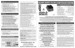
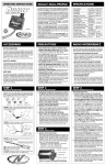
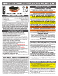
STEP 5 - INSTALL ESC & Receiver
STEP 4 INSTALL BRUSHLESS MOTOR (Continued)
2.ATTACH HEAT SINK TO ADAPTER PLATE
Using a 2.0mm Hex Wrench and four M3x8 FH screws, attach the
motor’s heat sink on to the motor adapter plate — the motor’s
back endbell (end with sensor harness) must be on the side of the
engraved name. Screw thread locking agent should be used
on these screws to prevent loosening — see Figure 11.
figure 11:
Motor Heat Sink
Installed on
Motor Adapter
Plate
1.INSTALL NOVAK HV BRUSHLESS ESC
BRUSHLESS CONVERSION KIT INSTRUCTIONS
a. Select mounting position for ESC — refer to Figure 14 (on
specifics sheet).
CONVERSION KITS AVAILABLE
•For OFNA & Kyosho Dual Battery Setups: refer to Figure 15
•For Losi 8ight: refer to Figures 20 & 21 (on specifics sheet).
Note: Be sure there is adequate
ventilation over ESC’s heat sink!
b. Using the included double-sided tape, mount ESC to chassis.
Back endbell must be on
same side as engraved
name on motor plate
Motor fan mounts square and
flush on heat sink using four
4-40x1/2” socket cap screws.
Fan shown above heat sink
to show screw detail.
The following Novak Brushless Conversion Kits are available (Refer to
www.teamnovak.com for additional and/or updated kit compatibility information)
#5010 Associated® RC8TM for Team Associated RC-8 Buggy
#5011 CEN® MatrixTM for CEN Matrix C-1 Buggy
#5012 Hot Bodies® LightningTM for Hot Bodies Lightning2 Evo Pro Buggy
#5013 Kyosho® InfernoTM for Kyosho Inferno 777, 777 SP-1, SP-2,
SP-2WC, and Sport ST-R Buggies
#5014 Mugen® MBX5TM for Mugen MBX5 and MBX5R Buggies
#5015 OFNA® 9.5TM/UltraTM for OFNA 9.5 Series Buggies (ViolatorTM,
RavengerTM and Jammin X1TM) and the OFNA Ultra Series Buggies (MBXTM,
CompTM and LX1TM)
#5016 OFNA® Hyper 8TM for OFNA Hyper 8 and Hyper 8.5 Buggies
#5017 OFNA® Hyper 7TM for OFNA Hyper 7 Buggies
#5018 XRAY® XB8TM for X-Ray XB8 TQ and XB8 EC Buggies
#5019 Losi® 8ightTM for Team Losi 8ight Buggy
• ESC can be mounted to chassis with the included #6x1”
Phillips FH self-tapping screws (see Figure 13) — chassis
and/or stone guard will need to be drilled and holes
countersunk to do this.
c. Refer to the ESC instructions for further installation instructions.
2.INSTALL RECEIVER AND ANTENNA MOUNT
a.Select mounting position for receiver and antenna — refer to
Figure 14 (on specifics sheet).
•For OFNA & Kyosho Dual Battery Setups: refer to Figure 15
•For Losi 8ight: refer to Figure 14 (on specifics sheet).
b.Install Receiver: refer to receiver instructions.
c.Using a 2.0mm Hex Wrench, install plastic antenna mount (in
Add’l Hardware Bag — refer to Figure 13), using the M3x8 FH
screw. Drill out the other hole (as needed) to fit the antenna
tube that came with nitro vehicle.
M3x8 FH
screws (4)
3.INSTALL MOTOR PINION GEAR
Install a Mod 1 pinion gear to the output shaft. A hardened steel,
high-strength pinion gear is recommended with a 5mm bore. Novak
offers these pinion gears in 11T-16T (Novak #5100-#5105). Refer to
Figure 14 (on specifics sheet) for recommended pinion gear.
figure 13: Additional Hardware Bag Contents (#65-5010-3)
4-40x1/2” Socket Cap Screw (4)
4.INSTALL BRUSHLESS MOTOR ASSEMBLY
Each kit has a unique motor adapter plate.
• Slotted Plates: require four M4x10 FH screws and four M4
Nylon insert lock nuts — see Figure 12.
• Non-Slotted Plates: require the four screws (and cupped washers
depending on model) that were originally used to mount the nitro engine
to the chassis. Use thread-locking agent on these screws.
Antenna Mount (1)
Servo Stand-Offs (4)
M3x8 FH Screw (1)
The Ultimate Conversion Kit to Convert Nitro Buggies to Electric Power!
Novak’s Brushless Conversion Kits allow drivers to experience the benefits of brushless with a leaner, cleaner, less noisy 1/8-scale car with faster acceleration and
speeds comparable to nitro. The Novak Brushless Conversion Kits were designed specifically for Novak’s 550-size, HV-Series of sensored brushless motors and
include all of the necessary conversion components. A Novak High-Voltage Brushless ESC and HV Brushless Motor are not included but required for completion.
INCLUDED ITEMS
PRECAUTIONS
figure 1: Included Items
PLEASE READ ALL INSTRUCTIONS BEFORE STARTING
VEHICLE CONVERSION. The instructions for this
conversion kit are guidelines for installation. Some
customization and variance may be needed.
There are four Hardware Bags included and are detailed in the
relevant instruction sections.
c
a
Installation of this kit requires the use of power tools. Adult supervision is
required for users under the age of 18.
b
NOVAK 550-SIZE MOTORS ONLY
GEARING setup
Refer to Vehicle Specifics Sheet for Novak’s
recommended Gearing Starting Points.
figure 12: Motor Adapter Plate Installation (slotted plate shown)
Motor operating temperature is the
ONLY way to set vehicle gearing
Note: Motor and Heat Sink removed to show screw detail
BE SURE TO CREATE
SUFFICIENT VENTILATION
For slotted plates, use
four, M4x10 FH screws
and four M4 lock nuts.
d. BATTERY BOX
STRAPS (2)
• Using a 3/32” Hex Wrench, screw four 4-40x1/2” socket cap
screws (in Add’l Hardware Bag) through fan into heat sink — see
Figure 11 & Figure 14 (on specifics sheet).
Novak Electronics, Inc.
P4
Monday-Friday: 8:00am-5:00pm (PST) • (949) 833-8873 • FAX (949) 833-1631
E-MAIL: [email protected] • WEB: www.teamnovak.com
NOVAK HV BRUSHLESS SYSTEM REQUIRED
This kit requires a Novak HV Brushless ESC and
a 550-size HV Brushless Motor for completion.
LEAD-FREE 3% SILVER SOLDER [Novak kit #5830]
tools needed
• 3.6mm or 9/64” DRill bit
• 4mm or 5/32” drill bit
• 3/32” HEX WRENCH
f. Y-HARNESS
THERMAL PASTE,
MOUNTING TAPE
& ZIP TIES*
*not shown
HV BRUSHLESS MOTOR 5MM UPGRADE KIT [Novak #5924]
• Power hand drill
Quality Racing Electronics since 1978
e
ACCESSORIES
• Rotory/dremel tool
with cut-off wheel and
sanding drum
For optimal performance, place the included 40x40mm fan square
and flush on top of heat sink (refer to label on fan for direction).
d
HIGH QUALITY BATTERIES ONLY!
SUPER-FLEX SILICONE 14G WIRE [Novak kits #5500 & 5508]
5.INSTALL MOTOR FAN ON HEAT SINK
f
Stick type or pre-assembled NiMH sport packs are NOT RECOMMENDED.
Novak recommends using high quality (20C minimum) Li-Poly battery packs
for better balance, lower vehicle weight and longer run times.
Change the gearing to avoid overheating!
DO NOT FREE-REV MOTOR!
Note: For non-slotted plates, use the hardware that was included with
your Nitro engine. Do not use M4x10 FH screws of M4 lock nuts.
FOLLOW ESC & MOTOR PRECAUTIONS
Refer to Novak’s “Precaution” sections of instruction manuals.
mod 1 pinion gears for 5mm shaft [Novak #5100-5105]
Free-running your brushless motor in a no-load condition can cause rotor
failure & ESC transistor damage and will void the product’s warranty.
e. MOTOR
COOLING FAN
Refer to the warranty statement of your vehicle’s owner’s manual.
The Motor and Speed Control should not exceed
160-170°F MAX at end of the run!
a. MOTOR
HEAT SINK
b. MOTOR
ADAPTER
PLATE
c. BATTERY
BOXES (2)
The motor heat sink included in this kit was specifically developed for Novak
550-size, HV-Series of Brushless Motors. Use of the heat sink on other
motors may cause damage to the motor.
MAY VOID VEHICLE’S WARRANTY
• For Losi 8ight Vehicle: refer to Figures 17-19 (on specifics sheet).
• Use included Y-harness (see Figure 1) to plug the motor fan and
ESC fan into the Novak HV High-Voltage Brushless ESC.
Car models listed are the registered trademarks of their respective company.
MUST BE 18 YEARS OR OLDER
#6x1” Phillips FH Self-Tapping
Screw (2)
Mount motor assembly to chassis with the proper screws and
adjust gear mesh before tightening, being sure that the two
clamping screw holes in the heat sink face the outside of the
buggy. The motor’s solder tabs should face in the direction that
will provide the shortest wire length from the ESC to the motor.
#55-5010-1 • 4/2008
*HV4.5 is for high-speed runs only
Compatible Novak HV Brushless Motors:
• HV4.5*, HV5.5, HV6.5, or HV7.5 High-Voltage
Brushless Motor with 5mm shaft (#3524-3527)
• HV4.5* & HV6.5 High-Voltage Brushless Motors
(#3424 & #3426) and HV4400 (original). These
motors have a 1/8” shaft and need to be updated
with a 5mm rotor with Novak #5924 Upgrade Kit.
Product Warranty
• 3.0mm hex wrench
This product is guaranteed to be free from defects in materials or workmanship for a period of
120 days from the original date of purchase (verified by dated, itemized sales receipt). Warranty does not cover incorrect installation, components worn by use, or any damage caused
by a crash, flooding or natural disaster. Because Novak has no control over the installation of
this conversion kit, no liability may be assumed nor will be accepted for any damage resulting
from the use of this product. By the act of installing the components of this conversion kit, user
accepts all resulting liability. In no case shall our liability exceed the product’s original cost. We
reserve the right to modify warranty provisions without notice.
• 2.5mm hex wrench
• 2.0mm hex wrench
• PHILLIPS SCREWDRIVER
• 90o Counter sink tool
• Thread-locking agent
P1
©2008 Novak Electronics, Inc. • All Rights Reserved • No part of these instructions may be
reproduced without the written permission of Novak Electronics, Inc.
STEP 1 - Remove Nitro Components
STEP 3 - INSTALL BATTERY BOX
1.REMOVE NITRO COMPONENTS
For optimal side-to-side balance and vehicle performance,
Novak recommends installing one battery box. Novak’s battery
box can accommodate two, 2S Li-Po packs, which provides excellent
power and runtime.
Remove the following items from your buggy (see Figure 2).
• Nitro Engine
• Muffler
• Fuel Tank
• Radio Box (keep for Losi 8ight)
• Throttle Servo
•Steering Servo and Mount
(keep for all conversions)
•Mechanical brake assembly
parts
• Other parts specific to the fuel
engine (keep mounting screws)
STEP 3 INSTALL BATTERY BOX (Continued)
For Dual Battery Box Setups: Refer to Figure 15 on the backside
of the vehicle-specific sheet for dual battery box instructions for the
OFNA 9.5 (#5015) and Kyosho Inferno (#5013) series buggies. The
other buggies require major modifications to mount a second battery
box, and we don’t recommend it.
figure 2:
M4x16 BH Screw (2)
battery box with a 3.6mm (or 9/64”) drill.
b.Position the battery box in the buggy. The front of battery box and
the battery wires must clear the steering servo and its linkages.
The back of the battery box must go inward as far as possible
so that it will clear the body. Box must be at least 4mm (or 5/32”)
away from the spur gear. Refer to Figure 14 (on vehicle specifics
sheet) for correct location.
Body Clip (1)
M4x20 BH Screw (2)
Rubber Foot (1)
Sample Location
of Drilled Mounting
Holes for Battery
Box.
Hole in metal
chassis*
M3x8 BH Screw (2)
If you are starting with an old buggy that is full of greasy dirt, we
highly recommend that you thoroughly clean your buggy.
Battery
Box
spacers
STEP 4 - INSTALL BRUSHLESS MOTOR
Plastic Spacer (2)
M4x9 Washer (6)
For STEPS 2-5: Refer to the vehicle-specific sheet that
is located in the bag with the motor adapter plate.
Hardware Bag contents in Figures
5, 9 & 13 are actual size and can be
used for comparison.
The following instructions are for a single battery box installation.
STEP 2 - INSTALL STEERING SERVO
1.LOCATE POSITION FOR BATTERY BOX
For the best side-to-side balance, we recommend installing the
battery box on the right side of vehicle (left side for Losi 8ight).
For Losi 8ight Vehicle: refer to Figure 16 (on specifics sheet).
1.REMOVE & MODIFY SERVO TRAY
2.SELECT PROPER BATTERY BOX & HARDWARE
Cut off the part of the servo tray that holds the throttle servo. This is
best done with a Dremel Tool with a carbide cutting wheel. Round
off the sharp corners where necessary — see Figures 3 & 4.
Make sure that the three or four (depending on kit) servo tray
mounting post holes remain intact.
On the bottom of the battery box, there is a LEFT and RIGHT
notation. Follow the list below to know which box and what hardware
is used to correctly mount the battery box in your vehicle.
Model Number
Battery
Box(es)
Screw
Front*
Screw
Rear*
Front/Rear
#Washers
Rubber
Foot
Left
BH
FH
0/6
1
Left
FH
FH
6/6
1
Right
FH
FH
6/6
0
#5012 Hot Bodies Lightning
Left
BH
FH
2/6
1
#5013 Kyosho Inferno
Left
BH
FH
3/6
1
figure 4:
#5013 Kyosho Inferno (Dual)
Both
BH (2)
BH (2)
0/0
0
Modified Servo Tray*
Be sure to smooth
sharp corners and keep
mounting holes intact.
#5014 Mugen MBX5
Right
BH
FH
2/4
1
#5015 OFNA 9.5 / Ultra
Right
FH
FH
6/6
1
#5015 OFNA 9.5/Ultra (Dual)
Both
BH (2)
BH (2)
0/0
0
*OFNA Hyper 7 Servo Tray shown
#5016 OFNA Hyper 8
Left
BH
FH
0/5
1
#5017 OFNA Hyper 7
Left
BH
FH
0/5
1
#5018 XRAY XB8
Left
BH
FH
0/8
1
#5019 Losi 8ight
Left
FH
BH
5/4
1
figure 3:
#5010 Associated RC8
Servo Tray*
Cut servo
tray along
line with a
Dremel Tool
(Horiz)
#5010 Associated RC8 (Vert)
#5011 CEN Matrix
* BH is for M4x16 button head screw; FH is for M4x20 flat head screw.
P2
M3x8 BH
Screw
Hole in plastic
stone guard*
*hole location for typical battery
box location.
2.CLEAN BUGGY
Note: The M4 post should be placed on whichever end of the battery
box that has body clearance for it, which is usually the back.
figure 8: Battery Box with Thin Batteries
XRAY XB8 buggy
shown. Refer also to
Figure 14 on insert.
XRAY XB8 Buggy Shown
2.RE-INSTALL STEERING SERVO ASSEMBLY
Install steering servo assembly to chassis and hook up steering
linkage. Refer to Figure 14 on specifics sheet (or Figure 15 for
dual battery set-ups if applicable).
• For Associated RC-8: You can either mount the steering
servo upright (vertical) or on its side (horizontal).
figure 6:
M4 Post (1)
M4x20 FH Screw (2)
a. With a 2.5mm Hex Wrench, screw one end of the battery strap
into battery box with a M4x20 BH screw — refer to Figure 7.
b At the other end, screw in an M4 post and use a body clip to
fasten the battery strap.
c. The size of the batteries will determine which direction you place
the strap on the box. For thin batteries, attach one of the included
plastic spacers with an M3x8 BH screw on each 3mm spacer
hole — refer to Figure 8. Tighten using a 2.0mm Hex Wrench.
a Drill completely through the two mounting screw holes in the
figure 5: Battery Box Hardware Bag Contents (#65-5010-1)
Note: There are two bags included — one for each battery box.
Buggy with Components Removed
5.INSTALL BATTERY BOX HOLD DOWN STRAP
3.LOCATE & DRILL BATTERY BOX MOUNTING HOLES
(continued)
A Novak 550-size brushless motor is required for this
conversion kit. If the motor does not have a 5mm output shaft,
the motor needs to be upgraded (Novak Kit #5924). This step uses
parts from the Motor Hardware Bag — see Figure 9.
c.With the battery box in the correct location (refer to Figure 14
on specifics sheet and double check this location), spot drill the
first hole (front or back) with a 3.6mm (or 9/64”) drill bit, going
down through the hole in the battery box — Refer to Figure 6.
d.From one of the Battery Box Hardware Bags, gather the needed
screws and washers — see table & Figure 5. A button head (BH)
screw mounts the battery box to the plastic stone guard, and the
flat head (FH) screw mounts battery box to the metal chassis.
e.After you have marked the hole, remove box and drill a 4mm hole
in this location. Using a 2.5mm Hex Wrench, mount box with the
proper screw (see table) and correct number of washers. Snug up
screw. This allows you to more accurately locate second hole.
figure 9: Motor Hardware Bag Contents (#65-5010-2)
Completed
Battery Box
e
d
b
a
M4 Nylon Insert Lock Nut (4)
550-size brushless motor by removing the three 4-40 cap head
screws, using a 3/32” Hex Wrench and sliding off the endbell
— being careful not to lose any shim washers.
b.Using the included cotton swab, apply a thin coat of thermal
paste to outside of the motor’s stator and to the inside of the
heat sink sleeve.
a.M4x20 BH
Screw
b.SPACER
HOLES
c.Route
Battery
Wires in
Cut-out
d.M4 POST &
BODY CLIP
e. 2S LI-PO
BATTERY
PACKS (2)
c.Slide heat sink onto motor, being sure that the two clamping
screw holes in the heat sink face the outside of buggy — see
Figure 10. Refer to Figure 14 (or Fig. 15 for applicable dual
setups) on the specifics sheet for direction of motor solder tabs.
figure 10:
Motor
Heat Sink
Installation
(not shown)
4.MOUNT BATTERY BOX
Remount the battery box with the proper screws, washers and
Slide heat sink
on to motor
Apply thin coat of thermal
paste to stator.
Clamping holes in
heat sink face toward
outside of buggy.
rubber foot (if needed).
• Screw from the bottom of the chassis.
• If a rubber foot is used, it will go under the inside rear corner of
the battery box for more rigidity, except Losi 8ight — see Figure
14 (on vehicle specifics sheet) for correct location.
Note: In some installations, some of the stone guard screw posts
may interfere with the ribs on the bottom of the battery box. Simply
remove that portion of the rib until you have proper clearance.
When you are done, you should have a stable battery box with
little rocking motion.
(continued)
M3x8 FH Screw (4)
a. Remove front endbell (end with output shaft) and sleeve of Novak
Note: If hole is in the metal chassis, the hole must be countersunk
on the bottom of the chassis.
fig. 7:
M4x10 FH Screw (4)
1.INSTALL MOTOR HEAT SINK
f. Repeat steps c through e for the second battery box hole — see
Figure 7 for completed battery box.
c
M3x16 BH Screw (2)
P3
d.Replace front endbell and tighten the three motor screws.
e. Slightly re-loosen the three motor screws (one turn each) and,
using a 2.0mm Hex Wrench, tighten the M3x16 BH heat sink
clamping screws.
f. Re-tighten the three 4-40 cap head screws
(continued on back)
on the motor’s front endbell.