1
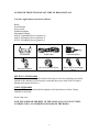
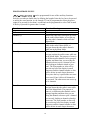
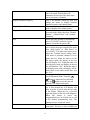
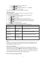
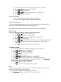
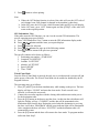
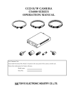
CS4000 AND CS4001 USERS MANUAL
FM HANDHELD TRANCEIVER
CONNECT SYSTEMS INCORPORATED
1802 Eastman Ave., Suite 116
Ventura CA 93003
VERSION 1.00
Copyright 2010 by Connect Systems Incorporated
GUIDE FOR THOSE THAT DO NOT LIKE TO READ MANUALS
You have eight items in your box as follows:
Radio
Fixed Bracket
Power Cable
Hand Microphone
Microphone Hanger
M4*10 Combination Screw (quantity 4)
M4*16 Self-tapping Screw (quantity 2)
M5*16 Self-tapping Screw (quantity 4)
Fixed bracket
Power Cable
Hand Microphone
Microphone Hanger
M4*10 Combination Screw
M5*16 / M4*16 Self-tapping
Screw
SETTING UP THE RADIO
Please use the service of a qualified radio technician as it involves attaching an external
antenna to the antenna jack and requires connecting the power cable to the car battery
through some protection device.
USING THE RADIO
Press the PTT switch on the hand microphone to talk and release to listen. Change
channels as necessary.
Wasn’t that easy!
NOW PLEASE READ THE REST OF THE MANUAL SO YOU WON’T KILL
YOURSELF OR A CO-WORKER AND DAMAGE THE RADIO.
2
Thank You
We are very grateful for you purchasing the Connect Systems Inc. brand professional
two-way radio. This radio incorporates the latest technology and can bring great
convenience to your life and work. The quality and function of this radio will meet your
demands for reliable communication.
Models Covered By This Manual
•
•
CS4000 UHF FM Mobile Transceiver
CS4001 VHF FM Mobile Transceiver
Notices To The User
•
•
•
Government laws under the FCC regulations prohibits radio communication with this
radio without being licensed.
Unlicensed use is illegal and subjects the user to punishment by fines and/or
imprisonment.
If this radio needs service, contact a qualified technician.
General Warnings
Do not use your radios under the following circumstances:
•
•
•
•
In the presence of potentially explosive atmospheres such as gas stations.
While being in any location where there is gasoline or other types of fuels.
In or near a site using explosives.
In a location where there is a potential for explosion because of the environment such
as grain elevators.
3
Warning on Danger of Radio Frequency and Magnetic Energy
The Model CS4000 and CS4001 generates both radio frequency energy and magnetic
energy while transmitting. Any transmitter has the potential to cause heating and other
thermal effects in your body. The amount of heating and other thermal effects is
determined by the power out from the radio and the distance from the body. To minimize
exposure the radio frequency energy and magnetic energy the user should use the radio
the minimum time required to achieve satisfactory communication, use minimum power,
and keep the radio as far away as possible.
This radio is classified as “Occupational Use Only”. That means the user of the radio is
aware of the potential hazards of using radios and is in a position to and familiar with
ways to minimize the hazards. This radio should not be used by the general public
because the general public has no knowledge of the hazards of two way radios and how
to minimize risk and might not be in a position to minimize those risks.
To minimize exposure to radio frequency energy and magnetic energy, the following
list should be observed:
•
•
•
When the PTT (push to talk) switch is pressed and you are transmitting, keep the
antenna away from any part of your body or the body of any bystanders. Normally
this is not a problem because the radio is in the vehicle and the antenna is on the
outside of the vehicle
Keep the transmission time to a minimum. Normal operation of a radio of this type is
five percent transmitting, five percent receiving, and the rest of the time in standby
mode. Any amount in excess of fifty percent of the available time in transmit mode is
considered excessive and should be avoided.
Use only an external antenna attached to the outside of the vehicle.
Other Warnings on Operation of the Radio
•
•
•
•
•
•
•
Do not expose the radio to long periods of direct sunlight or place the radio too close
to a heating appliance.
Do not place the radio in excessively dusty areas, humid areas, or on an unstable
surface.
Do not modify this radio for any reason.
Have this radio serviced only by a qualified technician.
If the radio emits smoke or strange odors, immediately turn off the radio and then
contact your local authorized service dealer.
This radio is not designed to work underwater. If your radio is in your vehicle and it
is underwater you might have serious problems such as breathing.
While this radio is waterproof, please keep windows closed during heavy rains.
4
FCC Warnings
This equipment generates or uses radio frequency energy. Changes or modifications to
this equipment may cause harmful interference unless the modifications are expressly
approved in the instruction manual. The user could lose the authority to operate this
equipment if an unauthorized change or modification is made.
This equipment has been tested and found to comply with the limits for a Class B digital
device, pursuant to Part 15 of the FCC rules. These limits are designed to provide
reasonable protection against harmful interference in a residential installation.
This equipment generates, uses and can generate radio frequency energy and, if not
installed and used in accordance with the instructions, may cause harmful interference to
radio communications. However, there is no guarantee that the interference will not occur
in a particular installation. If this equipment does cause harmful interference to radio or
television reception, which can be determined by turning the equipment off and on, the
user is encouraged to try to correct the interference by one or more of the following
measures:
• Reorient or relocate the receiving antenna.
• Increase the separation between the equipment and receiver.
• Connect the equipment to an outlet on a circuit different from that to which the
receiver is connected.
• Consult the dealer for technical assistance.
Other Warnings
Electronic devices such as pacemakers, medical equipment, and navigation equipment on
an airplane are susceptible to the energy generated from radios such as the CS4000 and
CS4001 if they are not adequately shielded. However this is not a portable device
because it requires a large battery so those warning normally do not apply.
• If there are signs posted in a hospital or some other health facility that says not to use
radios or cell phones, turn off your radio because they might interfere with the
sensitive medical equipment.
• If you are on board an aircraft it is recommended you not use this product because of
the potential to interfere with the aircraft navigation systems and other electronics on
board. Failure to do so without the express permission of the crew could cause you to
be detained by the FBI when you disembark from the plane. It also has the potential
to cause the plane to crash.
• This radio is heavy. If it falls on your toes it might require you to seek medical help to
repair a broken toe.
5
INSTRUCTIONS FOR THE RADIO TECHNICIAN
Connection of Power Cable
Check whether there is a hole for the power cable on the insulating board. If not, bore the
board with the suitable drill bit and fix a rubber grommet on it.
Have the cable pass through the insulating board into the car engine. Connect the red
conductor to the positive terminal of the Battery or an equivalent point and connect the
black conductor to the negative terminal of the battery or an equivalent point.
Make sure the wires are firmly attached and apply insulation as necessary.
Make sure the power cable is not too tight to allow convenient disassembly of the radio
while it is still connected to the power. This will allow you to attach the antenna to the
antenna jack without disconnecting the power cable.
Installing the Radio in the Vehicle
For passengers’ safety, fix the radio firmly on the fixed bracket so that the radio will not
be loosened in case of collision.
1)Mark a position on the instrument panel for the fixed bracket then drill a small hole
where it was marked. Install the fixed bracket with the 4 M5*16 self-tapping screws.
(Note: fix the radio at the position convenient for operation and control, and leave an
enough space for connection of the power cable and antenna cable.)
2)Slide the radio into the fixed bracket and attach it with 4 M4*10 combination screws
Use plus plain washers and spring washers as necessary. Different combinations of
holes are selectable to adjust the radio to the proper height and visual angle.
3)Connect the antenna and the power cable to the radio.
4)Install the microphone hanger at a position easy to use with the 2 M4*16 self-tapping
screws. (The microphone and its cable should be at a position not affecting safe
driving.)
5)Connect the microphone to the microphone jack on the front panel of the radio and
put it on the hanger.
Note: When replacing the protective fuse for the power cable, please use the one of the
same specification.
6
Radio Overview
Front Panel
⑾
( 1)
power button
Press this button for a long time (more than 1.5 seconds) to start or close the radio.
( 2) LED indicator
The red indicator will light when it transmitting. The green indicator will light when
it receiving.
The indicator will flicker and give an orange light when it receives DTMF, 2Tone,
or MDC signal indicating some selective call feature.
The red indicator flashes in the scanning process.
( 3)
/
button (programming button)
( 4) LCD display screen
For details, see “LCD Display”.
( 5) Volume Control knob
To be used to adjust volume.
( 6) Microphone/Programming Interface
( 7)
button (programming button)
( 8)
button (programming button)
( 9)
button (programming button)
( 10) button (programming button)
( 11) PTT button (on the hand microphone)
Press the PTT button first, and then speak to the microphone to transmit your voice
to the other radio. Do not press this button if you want to listen to the other some
other radio.
7
Display Screen
Display
Description
It means the receiving signal strength. 4 lines mean the strongest signal.
Transmission power level
”L” means the transmission of signal for the radio at the lower power;
”M” means the transmission of signal for the radio at the medium power;
”H” means the transmission of signal for the radio at the high power;
Receive Call display
The radio receives a selective call/call reminder.
Monitoring State display
Scanning State display
Companding State display
Talkaround State display
Interference State display
Decimal Point when displaying frequency
OST State display
Decimal Point when displaying CTCSS tone
P1
P2
P3
Rear Panel
⑷
⑶
⑵
⑴
( 1) Antenna Interface
( 2) Power Interface
( 3) 15Pin Extended Serial Interface
( 4) External Speaker Interface
8
BASIC OPERATION
1. Startup:
Press the red POWER button for at least 1.5 seconds to start or close the radio.
2. Volume
Press the “MONITOR” or “Squelch” button to listen to the background noise first,
and then adjust the volume by turning the volume control knob. Turning the Volume
knob to the right (clockwise) increases the volume and turning the Volume knob to
the left (counter-clockwise) decreases the volume.
3. Channel
The radio can provide 512 conventional channels (There are totally 16 groups and
each has at most 16 channels per group). Press the “CHANNEL UP” or “CHANNEL
DOWN” button to select the channel. Press the “GROUP UP” or “GROUP DOWN”
button to select the group you require.
4. Transmission
To send a call, press the PTT button and speak to the microphone in the normal voice.
Please keep the microphone close to your mouth. After speaking, please release the
PTT button.
5. Receive
The radio will return to the receiving state after you release the PTT button.
The radio dealer may have set the QT/DQT/LTR signaling in the program of your
radio. When QT/DQT/LTR is programmed, you can only hear calls from the other
radios if your QT/DQT/LTR matches the QT/DQT/LTR from the other radio.
9
PROGRAMMABLE KEYS
, , , , can be programmed for one of the auxiliary functions.
,
Each key can take on double duty by defining the length of time the key has to be pressed
to utilize the extra function. As an example, P2 can be programmed to select the power
output if its pressed for less than 1 second and can be programmed to select Talk Around
if the key is pressed for greater than 1 second.
Function
Function Meaning
Off
Channel Up
This key not used
Allows the radio-user to navigate up, while
in the radio's Menu Mode, or navigate up
thru the radio's channels while not in the
Menu Mode.
Allows the radio-user to navigate down
while in the radio's Menu Mode, or
navigate down thru the radio's channels
while not in the Menu Mode.
This key will allow the radio-user to
navigate up thru the radio's zones while not
in the Menu Mode. The purpose of zones is
so different radio channels can be grouped
together and then when you are using the
channel selector to pick a channel you are
only looking at channels related to your
zone. The Zone number or alias will be
near the top left of the display in small
characters and the channel number or alias
will be below in much larger characters.
Every time the key is pressed the next zone
is accessed. Zone 0 allows all channels to
be accessed. The other zones can access up
to 16 channels.
Channel Down
Zone Up
Zone Down
This key will allow the radio-user to
navigate down thru the radio's zones while
not in the Menu Mode. The purpose of
zones is so different radio channels can be
grouped together and then when you are
using the channel selector to pick a channel
you are only looking at channels related to
your zone. The Zone number or alias will
be near the top left of the display in small
characters and the channel number or alias
will be below in much larger characters.
10
Every time the key is pressed the previous
zone is accessed. Zone 0 allows all
channels to be accessed. The other zones
can access up to 16 channels.
This is an alternate action key that will
change the mode of display between
channel frequency and channel name
When this key is pressed, it will change the
mode of display to the channel name.
This is an alternate action key that switches
the mode on the display between “Channel
Number”, “Channel Alias”, and “Channel
Frequency”.
Allows the radio operator to dynamically
select CTCSS/DCS codes for a given
channel. Overrides the preset code.
This is an alternate action key allows the
user to select the power output of the radio
from “High Power” to “Mid Power” to
“Low Power”. This allows the radio-user to
adjust the Transmit Power setting radiowide unless a particular channel is set to
ignore this key. When the radio is in the
low power mode, the display on the top
line will display “LO”. When the radio is in
the mid power mode, the display on the top
line will blink the “LO”. When the radio is
in the high power mode, the display will be
blank where in the other modes there was
the “LO”.
Pressing this button enters the “Squelch
/
Level Adjustment Mode” Press the
button to adjust the level and then
press the button to save the selected
squelch level and quit this mode.
This is an alternate action key. When the
key is first pressed the LCD display will
show a picture of a lock near the top right
of the display. When the key is pressed
again the picture of the lock will disappear.
When this feature is active, the
programmable keys are locked out as well
as the manual programming keys. The
channel selector switch still works.
This allows the radio-user to enter or exit
scan mode. The key is only available for
Display Channel Frequency
Display Channel Name
Display Mode Switch
OST
Power Level
Squelch Level
Key Lock
Scan
11
Scan Lists where the User Programmable
field has been enabled. When the scan
mode is enabled the display will say
“SCAN” in large characters in the bottom
middle of the display. The purpose of the
scan function is to allow the user to
monitor multiple channels and stop at the
channel that is active. This would be useful
for a supervisor who needs to monitor the
activity among different groups of users.
When the radio lands on an unwanted
channel during scanning, pressing this key
will delete this channel temporarily. When
exiting scan mode and entering it again, the
channel will be restored. It is possible to
delete all the channel except the priority
channel.
This is an alternate action key that enables
or disables the Compander option.
Compander is a new standard feature in the
cellular phone industry and is supported
industry-wide. The purpose of Compander
is to reduce radio and airway noise, thus
enhancing audio clarity. When the
Compander option is enabled, a small “p”
will appear on the top of the display.
Nuisance Delete
Voice Compander
Public Address
You can enable or disable public address
function by this key. When enabled, the
text "PA" will be displayed on the LCD
and the radio can be used as a public
address system and your voice will be
heard by the surrounding people when you
press the PTT switch on the microphone.
This is an alternate action key that enables
or disables the Scrambler function. The
scrambler makes the voice unintelligible to
most people who do not have a compatible
radio. This prevents a third party from
listening in. When the radio is in the
scrambler mode, the display will show a
small box with a “T” inside in the top
middle of the screen.
This function selects a channel the dealer
has preprogrammed. The dealer can
preprogram either one channel or two
Scrambler
Home Channel
12
channels. If a single channel has been
preprogrammed, then pressing the key will
select the preprogrammed channel. If the
dealer has preprogrammed two channels,
then pressing the key will alternate between
the two preprogrammed channels. The
display will show the channel selected.
This is an alternate action key that selects
between talkaround mode and repeater
mode. In repeater mode, the radios talk
directly to another radio. In repeater mode,
the radios talk to the repeater and the
repeater in turn talks to another radio.
Repeater mode extends the range of the
radios. Talkaround mode is useful when the
repeater is out of range or the signal
strength of the repeater is not sufficient to
penetrate inside a building such as when
you have a firefighting incident.
For this key to work, the transmit and
receive frequencies must be different and
the key must not be disabled for the
channel you are using. When the key is
pressed and it goes in the talk around
mode, the display will show “Talkarnd
Mode” for a few seconds. When the key is
pressed and it goes in the repeater mode,
the display will show “Repeater Mode” for
a few seconds.
Talk Around
VOX
This is an alternative action key that
enables or disables VOX. When VOX is
enabled, the user only has to speak to
transmit. The PTT switch in this mode does
not have to be pressed. VOX is useful
when the operator of the radio cannot free
his hands to use the radio as what might
happen if you are driving. When the VOX
mode is enabled, the second line of the
display will show “Vox”.
Pressing the Monitor Momentary/Call
Cancel key allows monitoring the channel
for any voice traffic. The incoming signal
has to have the required squelch level
before anything can be heard. Releasing the
switch puts in back in the normal mode.
Monitor Momentary/Call Cancel
13
While the key is pressed, the display will
show MON on the second line of the
display. This key will also cancel the
current incoming call.
Normally the user will only hear messages
with the proper CTCSS or DCS codes. This
is to prevent the user from fatigue by
hearing all messages sent to everybody.
This switch bypasses that protection and
allows the user to hear all traffic on that
channel as long as the key is pressed.
This is an alternative action key that
enables or disables the monitor mode.
While in the monitor mode, any voice
traffic which has the required squelch level
will be heard. While in the monitor mode,
the display will show “MON” on the
second line of the display. This key will
also cancel the current incoming call.
Normally the user will only hear messages
with the proper CTCSS or DCS codes. This
is to prevent the user from fatigue by
hearing all messages sent to everybody.
This switch bypasses that protection and
allows the user to hear all traffic on that
channel as long as the radio is in the
monitor mode.
Pressing the “Squelch Off Momentary/Call
Cancel” key allows monitoring the channel
for any voice traffic. The incoming signal
does not to have any signal before anything
can be heard. That means if there is no
signal you will hear squelch noise.
Releasing the key puts it back in the
normal mode. While the key is pressed, the
display will show MON on the second line
of the display. This key will also cancel the
current incoming call.
By turning off the squelch, the user can
hear a weaker signal than if the squelch
was already enabled. This is both a
diagnostic tool and a feature. If the
transmitter from the originating user is
weak and does not get past the squelch,
then disabling the squelch will allow the
user to hear weak signals.
Monitor/Call Cancel
Squelch Momentary/Call Cancel
14
Squelch/Call Cancel
This is an alternative action key that
enables or disables the squelch mode.
While in the squelch mode, any voice
traffic will be heard no matter what the
squelch level. That means if there is no
signal you will hear squelch noise. While
the key is pressed, the display will show
“MON” on the second line of the display.
This key will also cancel the current
incoming call.
By turning off the squelch, the user can
hear a weaker signal than if the squelch
was already enabled. This is both a
diagnostic tool and a feature. If the
transmitter from the originating user is
weak and does not get past the squelch,
then disabling the squelch will allow the
user to hear weak signals.
Pressing the “Emergency” key will cause
the radio to transmit an emergency
message. The display will show in large
letters “EMERGENCY”.
Pressing the key designated as “emergency
alarm” will cause the radio will go into an
emergency mode and depending on the
dealer programming, will either generate a
local alarm or transmit an alarm to another
radio or both.
This has a similar function as the Lone
Worker mode. The biggest difference is the
user must press a key to start this function
verses the Lone Worker where not doing
something starts the function. This could be
used in situations where you want someone
to know there is an emergency but talking
over the radio might jeopardize the safety
of the user.
Pressing the “Cancel Emergency” key will
cancel the emergency transmission,
generate two beeps, and the cause the
“EMERGENCY” on the display to
disappear. This key would normally be
pressed if the emergency alarm condition is
resolved or the emergency alarm key has
been pressed by accident.
Emergency
Cancel Emergency
15
Radio Call
The Radio Call key is a multifunction key
that has the ability to generate Selective
Calls, Call Alerts, Radio Check, Kill, and
Active. The exact function(s) allowed is
determined by the dealer.
When the “Call 1” key is pressed, a
preprogrammed two tone, DTMF, or MDC
page will be sent. If the dealer programmed
the radio for side tone, the two tone,
DTMF, or MDC page will be heard as it is
being transmitted.
This is a paging feature that is used to
contact individual radio or sometimes to set
off certain types of alarming features.
When you set it for DTMF, two tone, or
MDC the other radio has to be able to
receive the corresponding code. Not all
radios have the ability to respond to
paging.
When the “Call 2” key is pressed, a
preprogrammed two tone, DTMF, or MDC
page will be sent. If the dealer programmed
the radio for side tone, the two tone,
DTMF, or MDC page will be heard as it is
being transmitted.
This is a paging feature that is used to
contact individual radio or sometimes to set
off certain types of alarming features.
When you set it for DTMF, two tone, or
MDC the other radio has to be able to
receive the corresponding code. Not all
radios have the ability to respond to
paging.
When the “Call 3” key is pressed, a
preprogrammed two tone, DTMF, or MDC
page will be sent. If the dealer programmed
the radio for side tone, the two tone,
DTMF, or MDC page will be heard as it is
being transmitted.
This is a paging feature that is used to
contact individual radio or sometimes to set
off certain types of alarming features.
When you set it for DTMF, two tone, or
MDC the other radio has to be able to
receive the corresponding code. Not all
radios have the ability to respond to
Call 1
Call 2
Call 3
16
paging.
When the “Call 4” key is pressed, a
preprogrammed two tone, DTMF, or MDC
page will be sent. If the dealer programmed
the radio for side tone, the two tone,
DTMF, or MDC page will be heard as it is
being transmitted.
This is a paging feature that is used to
contact individual radio or sometimes to set
off certain types of alarming features.
When you set it for DTMF, two tone, or
MDC the other radio has to be able to
receive the corresponding code. Not all
radios have the ability to respond to
paging.
Enables or disables Horn Alert function.
When enabled, an external DTMF or Two
Tone code can be used to set of the Horn
Alert.
When the “Lease Time” key is pressed, the
remaining time the radio can be used will
be displayed. The radio will show the
number of days, the number of hours, and
the number of minutes. Pressing any other
key will erase the remaining time from the
display.
This is an alternative key that enables or
disables the Lone Work mode. When the
Lone Work mode is enabled, a single beep
will be heard and the top line of the display
will show “SVC”. When the lone work
mode is disabled, a double beep will be
heard and the “SVC” will be erased from
the display. When the radio goes into the
emergency mode, the display will show in
large letters, “EMERGENCY”. The only
way to get out of the emergency mode is to
turn off the power.
The purpose of this function is to call for
help if the person holding this radio does
not press a key on the radio every so often.
Once the radio is set for the Lone Worker
mode, a timeout timer is started. At the end
of this time an alarm on the radio will
sound telling the user to press either the
Lone Worker reset key or any key,
Call 4
Horn Alert
Lease Time
Lone Work
17
depending how the unit is preprogrammed.
If the user does not press the appropriate
key soon after the radio starts to alarm, the
radio will go into an emergency mode and
depending on the dealer programming, will
either generate a local alarm or transmit an
alarm to another radio or both.
Enables or disables the speaker for
purposes of generating an alarm. When
enabled, an external DTMF or Two Tone
code can be used to set of the Speaker
Alert.
This allows the radio-user to edit a Scan
List. Scan List editing is only available for
Scan Lists where the User Programmable
field has been enabled
It's used to look over the GPS information
with GPS mobile.
This key is used to adjust the level of the
VOX. Level 1 is the least sensitive and
Level 10 is the most sensitive.
Pressing this button enters the “Vox Level
Adjustment Mode” Press the
/
button to adjust the level and then press
the button to save the selected Vox level
and quit this mode.
In/Out Speaker
Scan List Edit
GPS Information
Vox Level
Missed Call
The Missed calls key is used to display the
list of missed calls. As an example, you
leave your radio, and while you were gone
you received three calls.. When you come
back you can use the missed calls key to
see who have called you and then call those
parties back. This feature is not currently
supported.
This feature allow the users to change the
mode of the GPS Auto Tx . An alert tone
heard will enable the feature, and two alert
tone heard will disable the feature
GPS Auto Tx
18
CHANGING THE PARAMETERS FROM THE KEYPAD
Send Selective Call
A. Press “Menu Selection/Enter” button to enter the menu mode.
/
button until “RADIOCAL”.
B. Press
C. Press
button to select “SEL CALL”.
/
button until the required call list appears.
D. Press
E. Press “PTT” button to send the selective call.
F. Press “PTT” button and speak to the microphone in normal voice. Please keep the
microphone about 3 to 4 cm far from your mouth. After speaking, please loosen the
“PTT”.
G. Press
button to return to the previous operation.
Receive Selective Call
Receiving a selective call, you will hear the prompt tone and find the orange indicator
flashes.
icon flashes and the calling party’s ID code or name displays.
Press PPT button for callback.
Call Prompt
After the radio receives the call prompt, the prompt tone will sound and the orange
indicator flicker.
icon flashes and the calling party’s ID code or name shows until
someone answers. Press the “PTT” button for callback or other buttons for cancellation.
A. Press “Menu Selection/Enter” button to enter the menu mode.
B. Press
/
button until “RADIOCAL”.
button to select “CALL ALT”.
C. Press
D. Press
/
button until the required call list is showed.
E. Press “PTT” button to utter the selective call.
F. After calling, press
button to return the previous operation.
Select Group
According to the setup of the communication network, the vehicle mounted radio can be
distributed to different groups. Select the proper group to realize calling with the vehicle
mounted radio of different groups. Select the group through menu as follows:
A. Press the “Menu Selection/Enter” button to enter the menu mode.
/
button until “ZONE”.
B. Press
C. Press
button for selection.
D. Press
/
button until the group name you require is appeared.
button for selection.
E. Press
Select the group through “GROUP UP” or “GROUP DOWN”.
Talkaround
In the communication network, you can expand communication range through the
repeater, but when the mobile radio is out of the communication range, you can connect
with other radio in the talkaround method. The talkaround function can be showed by
.
Select talkaround by menu as follows:
A. Press the “Menu Selection/Enter” button to enter the menu mode.
19
B. Press
/
button until “RPTRTALK”.
C. Press
button for selection.
D. Press
/
button until “REPEATE” or “TALKRND”.
E. Press
button for confirmation.
Switch the talkaround or repeater mode through “talkaround”.
Miscellaneous Items
The miscellaneous items can help you customize some setups of the radio.
The operating steps go as follows:
A. Press the “Menu Selection/Enter” button to enter the menu mode.
B. Press
/
button until “UTILITY”.
C. Press
button for selection.
D. Press
/
button until the items you require are showed.
button for confirmation. The radio will show the current setup.
E. Press
F. Press
/
button to show all items that can be set with this item.
G. Press
button to select this setup.
button to return to the previous operation.
H. Press
Change the setup items in the following table as per the previous steps.
Items
Selectable Setups Functions
Squelch Level
SQL 0 ~ 9
Change the squelch level of the radio.
"SQL LEV "
Transmission Power
"PWR LOW "
Select transmission power among high,
"PWR LEV "
"PWR MID ",
medium and low levels.
"PWR HI "
VOX Level
VOX 0 ~ 9
Change the VOX level of the radio.
"VOX LEV "
Backlight
“BLED OFF"
Select among such modes of backlight as
"BACK LED"
"BLED ON "
“turnoff”, “normal turn-on” or “auto”.
"BL AUTO "
MCU software version ……
Show the software version.
display
Eg. “R01.00”
"SOFT VER"
Scan
In order to receive the calls from many channels, the radio can be programmed to scan
these channels. At most there are 16 channels in each scan list. Each channel can use a
scan list together with others or alone.
Start/Close Scan Function
You can press “SCAN” button directly from the menu to activate the scan function.
When the scan function is started, icon and your channel will display at the same time.
In the scan state, the red indicator will flicker. When the scan is stopped, the indicator
will stop flickering. During the period from the scan state the menu mode, the radio will
stop scanning. After the menu is quitted, the scanning will go on.
Enter the scan state through menu mode
20
A.
B.
C.
D.
E.
Press the “Menu Selection/Enter” button to enter the menu mode.
Press
/
button until “SYS SCAN”.
Press
button for selection.
/
button until “SCAN ON?” or “SCAN OF?”
Press
button for confirmation.
Press
Use the scan button
A. Press “SCAN” button to activate the scan function.
B. Press “SCAN” button again to close the scan function.
Cancel Noise Channel
If a channel continuously produces noise or interference, press the “Nuisance Delete”
button to cancel this channel from the scan list temporarily.
Note: the priority channel and the last one in the scan list cannot be canceled.
Edit Scan List
Press the “Menu Selection/Enter” button to enter the menu mode.
A. Press
/
button until “PROG LST”.
B. Press
button to select “SCAN LIST”.
C. Press
/
button until “ADD LST?” or DEL LST?”.
D. Press
button for selection.
/
button until the channel you want to add or cancel displays.
E. Press
F. Press
button to complete operation and the show “CHN SAVE” or
“CHN DEL”.
button to return to the previous operation.
G. Press
Set Priority Channel
A. Press the “Menu Selection/Enter” button to enter the menu mode.
B. Press
/
button until “PROG LST”.
button to select “SCAN LIST”.
C. Press
/
button until “ED PRIO?”.
D. Press
E. Press
button for selection.
F. Press
/
button until “PRIO#1?” or “PRIO#2?”.
G. Press
button to select the type of the required priority channel.
For example, in Step 7, the type of priority channel is “DES?”. Press
button to select the required priority channel.
H. Press
button to complete operation.
I. Press
button to return to the previous operation.
/
OST
In a certain specific channel, you can revise the QT/DQT encoding setup of current
channel. The operating steps go as follows:
A. Press the “OST” button to enter the OST menu mode.
/
button until the QT/DQT code/decode shows.
B. Press
21
C. Press
button to select quitting.
Note:
¾ Where the OST backup function is selected, the radio will save the OST code of
each channel even if the channel is changed or the machine is shut down.
¾ In the OST state, the LCD of the vehicle mounted radio and P2 icon will display.
¾ In the OST state, press “OST” button again and the QT/DQT of the radio will
return to the original position.
GPS Information View
If the radio starts the GPS function, you can view the current GPS information. The
specific operating steps go as follows:
A. Press “GPS Information View” button to enter the GPS information display mode.
/
button until the items you require displays.
B. Press
C. Press
button for selection.
/
button for page up of the following content.
D. Press
E. Press
button to return to the previous operation.
The specific content can be shown as follows:
1. Positioning star number: “STAR NUM”
2. Longitude “LONGITUD”
3. Latitude “LATITUDE”
4. Altitude “ALTITUDE”
5. Speed “SPEED”
6. Time “TIME”
7.
Wired Clone Mode
Once the Wired Clone Mode is entered, the only way to exit that mode is too turn off and
on the power of the radio. The Wired Clone Mode can be enabled or disabled by the PC
Program Software.
The operating steps go as follows:
1 Press [P1] and [P2] on the host simultaneously while turning on the power. The host
display will show “CLONE” and enter the clone mode. If such a mode is not
allowed, it will enter the user mode.
2 Connect the two radios together with the cloning cable and then turn on the power
for the destination radio.
3 Press the [P4] button on the host to start the clone. At this time the red indicator will
light, the Display will say “CLONING” and the data will be transmitted to the
destination radio from the host. During the period when the destination is receiving
the data, it will show “PROGRAM” and the green indicator light will be illuminated.
After completion the host will show “SUCCESS” and the destination radio will
automatically restart.
4 Press the [P4] button and the host will return to the clone mode. To program another
radio start from Step 2.
22