1
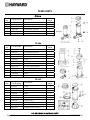
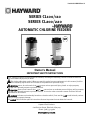
Part No ISCLSERIES Rev: B
SERIES CL100/110
SERIES CL200/220
by
AUTOMATIC CHLORINE FEEDERS
Owner’s Manual
IMPORTANT SAFETY INSTRUCTIONS
Basic safety precautions should always be followed, including the following: Failure to follow instructions
can cause severe injury and/or death.
This is the safety-alert symbol. When you see this symbol on your equipment or in this manual, look for
one of the following signal words and be alert to the potential for personal injury.
WARNING warns about hazards that could cause serious personal injury, death or major property
damage and if ignored presents a potential hazard.
CAUTION warns about hazards that will or can cause minor or moderate personal injury and/or property
damage and if ignored presents a potential hazard. It can also make consumers aware of actions that are
unpredictable and unsafe.
DANGER indicates an imminently hazardous situation which, if not avoided, will result in death, serious
injury, or major property damage.
The NOTICE label indicates special instructions that are important but not related to hazards.
Hayward Pool Products
620 Division Street, Elizabeth, NJ 07207
Phone: (908) 351.5400
www.haywardpool.com
WARNING - Read and follow all instructions in this owner’s manual and on the equipment.
Failure to follow instructions can cause severe injury and/or death.
WARNING – Suction Entrapment Hazard.
Suction in suction outlets and/or suction outlet covers which are, damaged, broken, cracked, missing, or unsecured can cause
severe injury and/or death due to the following entrapment hazards:
Hair Entrapment- Hair can become entangled in suction outlet cover.
Limb Entrapment- A limb inserted into an opening of a suction outlet sump or suction outlet cover that is damaged, broken,
cracked, missing, or not securely attached can result in a mechanical bind or swelling of the limb.
Body Suction Entrapment- A negative pressure applied to a large portion of the body or limbs can result in an entrapment.
Evisceration/ Disembowelment - A negative pressure applied directly to the intestines through an unprotected suction outlet
sump or suction outlet cover which is, damaged, broken, cracked, missing, or unsecured can result in evisceration/
disembowelment.
Mechanical Entrapment- There is potential for jewelry, swimsuit, hair decorations, finger, toe or knuckle to be caught in an
opening of a suction outlet cover resulting in mechanical entrapment.
WARNING - To Reduce the risk of Entrapment Hazards:
o
o
o
o
o
o
o
o
When outlets are small enough to be blocked by a person, a minimum of two functioning suction outlets per pump must
be installed. Suction outlets in the same plane (i.e. floor or wall), must be installed a minimum of three feet (3’) [1 meter]
apart, as measured from near point to near point.
Dual suction fittings shall be placed in such locations and distances to avoid “dual blockage” by a user.
Dual suction fittings shall not be located on seating areas or on the backrest for such seating areas.
The maximum system flow rate shall not exceed the flow rating of as listed on Table 1.
Never use Pool or Spa if any suction outlet component is damaged, broken, cracked, missing, or not securely attached.
Replace damaged, broken, cracked, missing, or not securely attached suction outlet components immediately.
In addition two or more suction outlets per pump installed in accordance with latest ASME, APSP Standards and CPSC
guidelines, follow all National, State, and Local codes applicable.
Installation of a vacuum release or vent system, which relieves entrapping suction, is recommended.
WARNING – Failure to remove pressure test plugs and/or plugs used in winterization of the pool/spa
from the suction outlets can result in an increase potential for suction entrapment as described above.
WARNING – Failure to keep suction outlet components clear of debris, such as leaves, dirt, hair, paper
and other material can result in an increase potential for suction entrapment as described above.
WARNING – Suction outlet components have a finite life, the cover/grate should be inspected
frequently and replaced at least every ten years or if found to be damaged, broken, cracked, missing, or not
securely attached.
CAUTION – Components such as the filtration system, pumps and heater must be positioned so as to
prevent their being used as means of access to the pool by young children.
WARNING – Never operate or test the circulation system at more than 50 PSI.
WARNING – Never change the filter control valve position while the pump is running.
WARNING – To reduce risk of injury, do not permit children to use or climb on this product. Closely supervise children at
all times. Components such as the filtration system, pumps, and heaters must be positioned to prevent children from using them
as a means of access to the pool.
WARNING – Hazardous Pressure. Pool and spa water circulation systems operate under hazardous pressure during
start up, normal operation, and after pump shut off. Stand clear of circulation system equipment during pump start up. Failure to
follow safety and operation instructions could result in violent separation of the pump housing and cover, and/or filter housing
and clamp due to pressure in the system, which could cause property damage, severe personal injury, or death. Before servicing
pool and spa water circulation system, all system and pump controls must be in off position and filter manual air relief valve must
be in open position. Before starting system pump, all system valves must be set in a position to allow system water to return
back to the pool. Do not change filter control valve position while system pump is running. Before starting system pump, fully
open filter manual air relief valve. Do not close filter manual air relief valve until a steady stream of water (not air or air and water)
is discharged.
WARNING – Separation Hazard. Failure to follow safety and operation instructions could result in violent separation
of pump and/or filter components. Strainer cover must be properly secured to pump housing with strainer cover lock ring. Before
servicing pool and spa circulation system, filters manual air relief valve must be in open position. Do not operate pool and spa
circulation system if a system component is not assembled properly, damaged, or missing. Do not operate pool and spa
circulation system unless filter manual air relief valve body is in locked position in filter upper body.
USE ONLY GENUINE HAYWARD PARTS
Page 2 of 8
AUTOMATIC CHLORINE FEEDERS
ISCLSERIES REV B
WARNING – Risk of Electric Shock. All electrical wiring MUST be in conformance with applicable local codes,
regulations, and the National Electric Code (NEC). Hazardous voltage can shock, burn, and cause death or serious property
damage. To reduce the risk of electric shock, do NOT use an extension cord to connect unit to electric supply. Provide a properly
located electrical receptacle. Before working on any electrical equipment, turn off power supply to the equipment.
WARNING – To reduce the risk of electric shock replace damaged wiring immediately. Locate conduit to prevent abuse
from lawn mowers, hedge trimmers and other equipment.
WARNING – Electrical ground all electrical equipment before connecting to electrical power supply. Failure to ground all
electrical equipment can cause serious or fatal electrical shock hazard.
WARNING – Do NOT ground to a gas supply line.
WARNING – To avoid dangerous or fatal electrical shock, turn OFF power to all electrical equipment before working on
electrical connections.
WARNING – Failure to bond all electrical equipment to pool structure will increase risk for electrocution and could result
in injury or death. To reduce the risk of electric shock, see installation instructions and consult a professional electrician on how
to bond all electrical equipment. Also, contact a licensed electrician for information on local electrical codes for bonding
requirements.
Notes to electrician: Use a solid copper conductor, size 8 or larger. Run a continuous wire from external bonding lug to
reinforcing rod or mesh. Connect a No. 8 AWG (8.4 mm2) [No. 6 AWG (13.3 mm2) for Canada] solid copper bonding wire to the
pressure wire connector provided on the electrical equipment and to all metal parts of swimming pool, spa, or hot tub, and metal
piping (except gas piping), and conduit within 5 ft. (1.5 m) of inside walls of swimming pool, spa, or hot tub.
IMPORTANT - Reference NEC codes for all wiring standards including, but not limited to, grounding, bonding and other general
wiring procedures.
WARNING – Risk of Electric Shock. Connect only to a branch circuit protected by a ground-fault circuit-interrupter (GFCI).
Contact a qualified electrician if you cannot verify that the circuit is protected by a GFCI.
WARNING – Risk of Electric Shock . The electrical equipment must be connected only to a supply circuit that is protected
by a ground-fault circuit-interrupter (GFCI). Such a GFCI should be provided by the installer and should be tested on a routine
basis. To test the GFCI, push the test button. The GFCI should interrupt power. Push reset button. Power should be restored. If
the GFCI fails to operate in this manner, the GFCI is defective. If the GFCI interrupts power to the electrical equipment without the
test button being pushed, a ground current is flowing, indicating the possibility of an electrical shock. Do not use this electrical
equipment. Disconnect the electrical equipment and have the problem corrected by a qualified service representative before
using.
CAUTION – The pump is intended for use with permanently-installed pools and may be used with hot tubs and spas if so
marked. Do not use with storable pools. A permanently-installed pool is constructed in or on the ground or in a building such
that it cannot be readily disassembled for storage. A storable pool is constructed so that it is capable of being readily
disassembled for storage and reassembled to its original integrity.
SAVE THESE INSTRUCTIONS
HAYWARD® Pool Products Limited Warranty
To original purchasers of this equipment, Hayward Pool Products, Inc. warrants its chemical feeders to be free from defects in materials and workmanship for
a period of ONE (1) year from the date of purchase, when used in single family residential applications.
The limited warranty excludes damage from freezing, negligence, improper installation, improper use or care or any Acts of God. Parts that fail or become
defective during the warranty period shall be repaired or replaced, at our option, within 90 days of the receipt of defective product, barring unforeseen delays,
without charge.
Proof of purchase is required for warranty service. In the event proof of purchase is not available, the manufacturing date of the product will be the sole
determination of the purchase date.
To obtain warranty service, please contact the place of purchase or the nearest Hayward Authorized Service Center. For assistance on your nearest Hayward
Authorized Service Center please visit us at www.haywardpool.com.
Hayward shall not be responsible for cartage, removal, repair or installation labor or any other such costs incurred in obtaining warranty replacements or
repair.
The Hayward Pool products warranty does not apply to components manufactured by others. For such products, the warranty established by the respective
manufacturer will apply.
The express limited warranty above constitutes the entire warranty of Hayward Pool Products with respect to its’ pool products and is in lieu of all other
warranties expressed or implied, including warranties of merchantability or fitness for a particular purpose. In no event shall Hayward Pool products be
responsible for any consequential, special or incidental damages of any nature.
Some states do not allow a limitation on how long an implied warranty lasts, or the exclusion of incidental or consequential damages, so the above limitation
may not apply to you. This warranty gives you specific legal rights, and you may also have other rights, which vary from state to state.
Hayward Pool Products
620 Division Street
Elizabeth, NJ 07207
*Supersedes all previous publications.
USE ONLY GENUINE HAYWARD PARTS
Page 3 of 8
AUTOMATIC CHLORINE FEEDERS
ISCLSERIES REV B
DANGER Mixing Chemicals or using fast dissolving chemicals may result in explosion and/or
fire. To avoid death, serious injury or major property damage:
Use only slow dissolving Trichlor Chlorine tablets.
Never use fast dissolving Trichlor Chlorine tablets.
Never mix chemicals.
Never mix Trichlor Chlorine tablets with Calcium Hypochlorite, or with any other form of
concentrated chlorine or other chemicals. Fire and/or explosion may result.
Never add any other types of chlorine, pH adjusters, shock treatments or algaecides through the
skimmer. If these products must be used, they should be added directly into the pool water.
Never isolate chlorine feeder with valves or other devices.
WARNING Wear eye and skin protection while maintaining or servicing this unit.
WARNING Do not inhale fumes from the chlorinator or chemical container.
WARNING Chlorine feeder may be under pressure. Use caution removing cover.
INSTALLATION:
CL–100/200
1. Your CL–100/200 automatic chlorine feeder is designed
for permanent installation in the pool water return line.
2. Always install the chlorine feeder after the heater. If
there is no heater, install after the filter.
CAUTION Damage to the heater or filter may result if concentrated chlorine is allowed to flow through them.
An in-line positive seal corrosion resistant check valve should be installed to reduce backflow of chlorine
gas when the system is shut off. If the chlorine feeder is located below water level, you may want to install a
check valve to prevent water backflow when operating/servicing the unit. The CL100 has this feature built in.
3. Both the CL–100/200 are furnished with 1 1/2” female threads. If PVC socket (solvent weld)
connections are desired, order SP1500UNPAK2, socket flush union end connectors package. For threaded
male and union connectors, order SP1500UNMPAK1 male union connector package (two required).
Thread or socket adapters may also be used. Only use pipe sealants formulated and approved for use
with ABS plastic connections (e.g. Teflon Tape, Permatex Form-A-Gasket No. 2, Laco Plasto-Joint
stick). Do not over tighten pipe fitting. Proper fitting makeup is hand tight plus 1 to 1 1 /2 turns
maximum.
NOTICE: After starting up system, re-check all connections for leaks. Re-tighten as required.
CAUTION Never install chlorine feeder directly into copper plumbing as pipe damage may occur. If you
have brass or bronze backwash valves, or other sensitive metallic components, consult your dealer for
precautions or recommendations for your particular system.
CL–110/220
1. The inlet connection should be made in the piping after the pump and before the filter. Mark location on
pipe.
2. The outlet connection should be made in the piping after the heater. If no heater is being used, connection
should be made after the filter. Mark location on pipe.
3. Based on the locations from steps. No. 1 and No. 2, cut tubing to required lengths. Be sure ends are cut
evenly and cleanly.
4. Wrap Teflon tape on larger male thread of Check Valve and thread it hand tight plus ½ turn into outlet
port of chlorinator. DO NOT OVER TIGHTEN.
NOTICE: The Check Valve is marked with a “dot”. It also has a ball that “clicks” when you shake it.
USE ONLY GENUINE HAYWARD PARTS
Page 4 of 8
AUTOMATIC CHLORINE FEEDERS
ISCLSERIES REV B
5. Wrap Teflon tape on larger male thread of the Inlet Fitting Adapter and thread it hand tight plus ½ turn into
the inlet port of chlorinator. DO NOT OVER TIGHTEN.
6. To connect inlet tubing to chlorinator, place Compression Nut over inlet tubing and slide nut up about 2”.
Insert the tubing all the way into the Inlet Fitting Adapter socket and, holding tubing in place, tighten nut
firmly by hand. Do not over tighten.
7. Connect outlet tubing to the Check Valve in the same manner as in step 6 above.
NOTICE: The saddle fittings and clamps are designed to fit the O.D. of 1 1/2” or 2” pipe.
8. Drill a 3/8” hole at location identified in Step 1 of Planning Installation section. Clean all burrs, shavings etc.
Fit Saddle Fitting, with gasket, into oval shaped hole in clamp and insert fitting into the 3/8” hole. Secure
clamp around Saddle Fitting, gasket and pipe and tighten securely to achieve a good seal. Do not over
tighten clamp.
9. Drill a 3/8” hole at location identified in Step 2 of Installation section for CL-110/220. Install Saddle Fitting
as in Step 8 above.
10. Connect inlet and outlet tubing to the Saddle Fittings with Compression Nuts as in Step 6 above. Do not
over tighten.
CAUTION Never install chlorine feeder directly into copper plumbing as pipe damage may occur. If you
have brass or bronze backwash valves, or other sensitive metallic components, consult your dealer for
precautions or recommendations for your particular system.
NOTICE: After starting up system, re-check all connections for leaks. Re-tighten as required.
DIRECTIONS FOR USE:
GENERAL
Before using your chlorinator, your pool/spa water should be properly balanced and conditioned and
should have a chlorine residual of approximately 1.0 to 1.5 ppm. Follow dealer and chemical
manufacturer’s directions and instructions.
Check chlorine residual daily and adjust the dial valve for more or less chlorine. The chlorine demand for
pools and spas varies based on usage, temperature, sunlight, etc. Initially, you’ll have to experiment to
determine the proper amount of chlorine and the correct valve setting required for your pool and filter time
cycle. Follow chemical manufacturer’s instructions for proper chlorine level.
DANGER Mixing Chemicals or using fast dissolving chemicals may result in explosion and/or fire.
To avoid death, serious injury or major property damage:
Use only slow dissolving Trichlor Chlorine tablets.
Never use fast dissolving Trichlor Chlorine tablets.
Never mix chemicals.
Never mix Trichlor Chlorine tablets with Calcium Hypochlorite, or with any other form of
concentrated chlorine or other chemicals. Fire and/or explosion may result.
Never add any other types of chlorine, pH adjusters, shock treatments or algaecides through the
skimmer. If these products must be used, they should be added directly into the pool water.
Never isolate chlorine feeder with valves or other devices.
WARNING Wear eye and skin protection while maintaining or servicing this unit.
USE ONLY GENUINE HAYWARD PARTS
Page 5 of 8
AUTOMATIC CHLORINE FEEDERS
ISCLSERIES REV B
WARNING Do not inhale fumes from the chlorinator or chemical container.
WARNING Chlorine feeder may be under pressure. Use caution removing cover.
REFILLING CHORINATOR
1. Shut off all pumps and pump timers.
2. Turn chlorine feeder flow control valve to “OFF”.
3. Verify chlorine feeder return line to pool is unrestricted.
4. Wait one minute to relieve system pressure before attempting to remove cover.
5. If installed in a flooded system, shut off valves to isolate chlorinator.
6. Remove cover.
7. Refill chlorine feeder with slow dissolving Trichlor-Chlorine Tablets.
8. Secure cover to chlorine feeder.
9. If installed in a flooded system, open valves to assure flow from pump to pool.
10.Turn flow control valve on chlorinator to desired setting and restart pump.
MAINTENANCE:
TO CHANGE O-RING CL100/110
1. Read and follow instructions in Steps 1 to 5 in Refilling Chlorinator section.
2. Remove the O-Ring and replace with a Genuine Hayward Part O-Ring (part no. CLX110K).
3. Replace cover. If chlorinator needs to be refilled, read and follow instructions in Steps 6 to 8 in Refilling
chlorinator section.
TO CHANGE O-RING CL200/220
1. Read and follow instructions in Steps 1 to 5 in Refilling Chlorinator section.
2. Pry off Logo Cap, located on the cover of the chlorinator. Unscrew and remove retainer screw. Cover may
now be slipped free of the Cover Cap.
3. Replace O-ring with a Genuine Hayward Part O-ring (part no. CLX200K). Reassemble being sure Slip Washers
are in place on stem of Cover (inside), and under head of Retaining Screw.
4. Replace cover. If chlorinator needs to be refilled, read and follow instructions in Steps 6 to 8 in Refilling
Chlorinator section.
TO REMOVE FLOW CONTROL VALVE HANDLE
Set pointer to FULL. Insert screwdriver in slot opposite pointer, lift up and rotate handle
counterclockwise. This allows the handle index lock tab to clear the body ridge.
TO INSTALL FLOW CONTROL VALVE HANDLE
1 The flow control valve handle Genuine Hayward Part (CLX200PA) is furnished in two pieces.
2 To install push the handle into the stem and fully install stem into body. You may have to remove handle and
reposition to assure the stem is fully seated.
3 Remove handle by pulling straight out.
4 Apply a single drop of Super Glue to the end of the stem, push on handle, positioned in the OFF position. Apply
pressure for 30 seconds.
WINTERIZING
Where freezing temperatures can be expected, drain all water and remove all chlorine from
chlorinator. (For in-line permanently installed unit remove drain plug). Carefully remove all tablets
and pieces of tablets. Rinse out chlorinator thoroughly with water. Replace cover and drain plug.
VACUUMING
When vacuuming, close flow control valve to prevent bypass of sediment and possible clogging of
control valve.
LUBRICATION
Never use petroleum type lubricants on Cover O-Ring. To lubricate use Genuine Hayward Part Jack’s Lube
No. 327 (Part No. SP032712).
USE ONLY GENUINE HAYWARD PARTS
Page 6 of 8
AUTOMATIC CHLORINE FEEDERS
ISCLSERIES REV B
SPARE PARTS
CL100
Ref
No.
Part Number
No.
Req’d
Description
1
CLX110C
Cover
1
2
CLX110K
O-Ring
1
3
CLX110FA
Control Knob Assembly
1
4
CLX220CV
Check Valve Assembly
1
5
SPX1700FGV
Drain Plug w/Gasket
1
SP032712
Hayward Jack’s Lub #327
1
CL200
Ref
No.
Part Number
No.
Req’d
Description
1
CLX200E
Logo Cap
1
2
CLX200G
Cover Retaining Screw
1
3
CLX200W
Slip Washer
2
4
CLX200C
Cover Cap
1
5
CLX200B
Cover
1
6
CLX200K
O-Ring
1
7
CLX200H
Feeder Tube (some models)
1
8
CLX200PA
Control Valve Assembly
1
9
SPX1700FA
Drain Plug w/Gasket
1
10
SPX1500UNPAK
Union Connectors–Socket (2)
-
11
CLX200BS
Base
1
SP032712
Hayward Jack’s Lub #327
1
CL110
Ref
No.
Part Number
Description
No.
Req’d
1
CLX100C
Cover
1
2
CLX110K
O--Ring
1
3
CLX110DA
Dial Flow Valve
2
4
CLX110B
Base
1
5
CLX220CV
Check Valve Assembly
1
6
CLX220H
Compression Nuts
4
7
CLX220G
Saddle Fitting
2
8
CLX220K
Saddle Clamp
2
9
CLX220J
Plastic Tubing–8 Ft.
1
SP032712
Hayward Jack’s Lub #327
1
USE ONLY GENUINE HAYWARD PARTS
Page 7 of 8
AUTOMATIC CHLORINE FEEDERS
ISCLSERIES REV B
Page 8 of 8
AUTOMATIC CHLORINE FEEDERS
ISCLSERIES REV B
CL220
Ref
No.
1
2
3
4
5
6
7
8
9
10
11
12
13
14
15
Part Number
CLX200E
CLX200G
CLX200W
CLX200C2
CLX200B
CLX200K
CLX200H
CLX200PA
CLX220B
CLX220CV
CLX220D
CLX220H
CLX220G
CLX220K
CLX220J
SP032712
No.
Req’d
Description
Logo Cap
Cover Retaining Screw
Slip Washer
Cover Cap
Cover
O-Ring
Feeder Tube (some models)
Control Valve Assembly
Base
Check Valve Assembly
Inlet Fitting Adapter
Compression Nuts
Saddle Fitting
Saddle Clamp
Plastic Tubing—8 ft.
Hayward Jack’s Lub #327
1
1
2
1
1
1
1
1
1
1
1
4
2
2
1
1
__________________________________________________________________________________________
PRODUCT REGISTRATION
(Retain For Your Records)
DATE OF INSTALLATION
____________________
▲Retain this Warranty Certificate (upper portion) in a safe and convenient location for your records.
DETACH HERE: Fill out bottom portion completely and mail within 10 days of purchase/installation or register online.
-----------------------------------------------------------------------------------------------------------------------------------------
AUTOMATIC CHLORINE FEEDERS
Warranty Card Registration
Register online at www.haywardpool.com
Please Print Clearly:
First Name____________________ Last Name_________________________
Street Address__________________________________________________
Years Pool has been in service
< 1 year
1-3
4-5
6-10
11-15
>15
Purchased from_____________________________
Builder
Retailer
Pool Service
Internet/Catalog
City_____________________________ State___________ Zip____________
Company Name_________________________________
Phone Number_____________________ Purchase Date_________________
Address_______________________________________
E-Mail Address__________________________________________________
City____________________ State_____ Zip__________
Serial Number
Phone_________________________________________
Type of Pool:
Model Number_____________________________________________________
Pool Capacity_______________(U.S. Gallons)
Concrete/Gunite
Vinyl
Fiberglass
Other_____________________________
New Installation
Replacement
Please include me on all e-mail communications regarding Hayward® Equipment or promotions.
Mail to: Hayward Pool Products, 620 Division Street, Elizabeth, NJ 07207
Attn: Warranty Dept
Or REGISTER YOUR WARRANTY ON-LINE AT WWW.HAYWARDPOOL.COM
Installation for:
In Ground
Hayward is a registered trademark of Hayward Industries, Inc.
© Hayward Pool Products. 2011 All rights reserved
Above Ground
Spa