1
ORION® Endpoint Utility
Software Application 2.6 for Laptop
ORI-UM-00019-EN-04 (February 2015)
User Manual
Page ii
ORI-UM-00019-EN-04
February 2015
CONTENTS
INTRODUCTION . . . . . . . . . . . . . . . . . . . . . . . . . . . . . . . . . . . . . . . . . . . . . . . . . . . . . . . . . 5
Audience and Purpose . . . . . . . . . . . . . . . . . . . . . . . . . . . . . . . . . . . . . . . . . . . . . . . . . . 5
Minimum System Requirements . . . . . . . . . . . . . . . . . . . . . . . . . . . . . . . . . . . . . . . . . . . . 5
About this Manual . . . . . . . . . . . . . . . . . . . . . . . . . . . . . . . . . . . . . . . . . . . . . . . . . . . . . 6
GETTING STARTED
WINDOWS UPDATES . . . . . . . . . . . . . . . . . . . . . . . . . . . . . . . . . . . . . . . . . . . . . . . . . . . . . . 8
EQUIPMENT SETUP . . . . . . . . . . . . . . . . . . . . . . . . . . . . . . . . . . . . . . . . . . . . . . . . . . . . . . . 9
IR Setup . . . . . . . . . . . . . . . . . . . . . . . . . . . . . . . . . . . . . . . . . . . . . . . . . . . . . . . . . . . . 9
RF Setup . . . . . . . . . . . . . . . . . . . . . . . . . . . . . . . . . . . . . . . . . . . . . . . . . . . . . . . . . . . 9
COM PORTS . . . . . . . . . . . . . . . . . . . . . . . . . . . . . . . . . . . . . . . . . . . . . . . . . . . . . . . . . . . 10
SOFTWARE STARTUP/EXIT . . . . . . . . . . . . . . . . . . . . . . . . . . . . . . . . . . . . . . . . . . . . . . . . . 11
Exiting the Software . . . . . . . . . . . . . . . . . . . . . . . . . . . . . . . . . . . . . . . . . . . . . . . . . . . 12
SETTINGS . . . . . . . . . . . . . . . . . . . . . . . . . . . . . . . . . . . . . . . . . . . . . . . . . . . . . . . . . . . . 13
USER GUIDE
MAIN SCREEN . . . . . . . . . . . . . . . . . . . . . . . . . . . . . . . . . . . . . . . . . . . . . . . . . . . . . . . . . 16
Main Functions . . . . . . . . . . . . . . . . . . . . . . . . . . . . . . . . . . . . . . . . . . . . . . . . . . . . . . 16
IR PROGRAMMING . . . . . . . . . . . . . . . . . . . . . . . . . . . . . . . . . . . . . . . . . . . . . . . . . . . . . . 17
Optional IR Programming Bracket . . . . . . . . . . . . . . . . . . . . . . . . . . . . . . . . . . . . . . . . . . 17
IR Programming Fields . . . . . . . . . . . . . . . . . . . . . . . . . . . . . . . . . . . . . . . . . . . . . . . . . . 17
IR Programming Buttons . . . . . . . . . . . . . . . . . . . . . . . . . . . . . . . . . . . . . . . . . . . . . . . . 20
Reading and Programming Endpoints . . . . . . . . . . . . . . . . . . . . . . . . . . . . . . . . . . . . . . . . 21
Stop, Pause, Start . . . . . . . . . . . . . . . . . . . . . . . . . . . . . . . . . . . . . . . . . . . . . . . . . . . . . 22
Programming an RTR Endpoint to the Odometer Setting . . . . . . . . . . . . . . . . . . . . . . . . . . . 23
Programming Water Meter Type, Size and Units of Measure (ORION ME/SE) . . . . . . . . . . . . . . . 25
Force Read (Encoder Output) . . . . . . . . . . . . . . . . . . . . . . . . . . . . . . . . . . . . . . . . . . . . . 26
Programming Gas Endpoints . . . . . . . . . . . . . . . . . . . . . . . . . . . . . . . . . . . . . . . . . . . . . . 27
GPS Location (ORION ME/SE) . . . . . . . . . . . . . . . . . . . . . . . . . . . . . . . . . . . . . . . . . . . . . . 30
Flow Rate Study (ORION ME/SE) . . . . . . . . . . . . . . . . . . . . . . . . . . . . . . . . . . . . . . . . . . . . 31
QUICK READ . . . . . . . . . . . . . . . . . . . . . . . . . . . . . . . . . . . . . . . . . . . . . . . . . . . . . . . . . . 32
RF Quick Read Fields . . . . . . . . . . . . . . . . . . . . . . . . . . . . . . . . . . . . . . . . . . . . . . . . . . . 32
February 2015
ORI-UM-00019-EN-04
Page iii
RF Quick Read Buttons . . . . . . . . . . . . . . . . . . . . . . . . . . . . . . . . . . . . . . . . . . . . . . . . . . 33
RF Quick Read - All Endpoints . . . . . . . . . . . . . . . . . . . . . . . . . . . . . . . . . . . . . . . . . . . . . 34
Changing Quick Read Technology . . . . . . . . . . . . . . . . . . . . . . . . . . . . . . . . . . . . . . . . . . 35
RF Quick Read - Single Endpoint . . . . . . . . . . . . . . . . . . . . . . . . . . . . . . . . . . . . . . . . . . . 35
Advanced Endpoint Details (ORION ME/SE) . . . . . . . . . . . . . . . . . . . . . . . . . . . . . . . . . . . . 36
PROFILE EXTRACTION . . . . . . . . . . . . . . . . . . . . . . . . . . . . . . . . . . . . . . . . . . . . . . . . . . . . 37
Profile Extraction Screen . . . . . . . . . . . . . . . . . . . . . . . . . . . . . . . . . . . . . . . . . . . . . . . . 37
IR Profile Extraction . . . . . . . . . . . . . . . . . . . . . . . . . . . . . . . . . . . . . . . . . . . . . . . . . . . . 38
RF Profile Extraction (ORION ME/SE) . . . . . . . . . . . . . . . . . . . . . . . . . . . . . . . . . . . . . . . . . 40
Viewing Profile Data . . . . . . . . . . . . . . . . . . . . . . . . . . . . . . . . . . . . . . . . . . . . . . . . . . . 42
Adding Profile Data Files . . . . . . . . . . . . . . . . . . . . . . . . . . . . . . . . . . . . . . . . . . . . . . . . 44
Deleting Profile Data Files . . . . . . . . . . . . . . . . . . . . . . . . . . . . . . . . . . . . . . . . . . . . . . . . 44
APPENDIX
GLOSSARY . . . . . . . . . . . . . . . . . . . . . . . . . . . . . . . . . . . . . . . . . . . . . . . . . . . . . . . . . . . . 46
REMOVING PREVIOUS SOFTWARE . . . . . . . . . . . . . . . . . . . . . . . . . . . . . . . . . . . . . . . . . . . . 47
Removing Software – Windows 7 . . . . . . . . . . . . . . . . . . . . . . . . . . . . . . . . . . . . . . . . . . . 47
Removing Software – Windows XP . . . . . . . . . . . . . . . . . . . . . . . . . . . . . . . . . . . . . . . . . . 48
INSTALLING THE SOFTWARE . . . . . . . . . . . . . . . . . . . . . . . . . . . . . . . . . . . . . . . . . . . . . . . . 49
Additional Steps - Windows 7 Users Only . . . . . . . . . . . . . . . . . . . . . . . . . . . . . . . . . . . . . . 52
Installing the ME Driver . . . . . . . . . . . . . . . . . . . . . . . . . . . . . . . . . . . . . . . . . . . . . . . . . 53
Configuring the USB Settings (Windows 7 and Windows XP) . . . . . . . . . . . . . . . . . . . . . . . . . 61
Page iv
ORI-UM-00019-EN-04
February 2015
Introduction
INTRODUCTION
This manual is the guide for using the ORION® Endpoint Utility 2.6.x software. Instructions for installing the software are also
included.
Audience and Purpose
The ORION Endpoint Utility software is an application designed for users who read and program ORION Migratable (ME),
Fixed Network (SE) and Classic (CE) water and gas endpoints. Depending on the endpoint technology, the software can also
be used to extract endpoint historical profile data using IR or RF technology.
Minimum System Requirements
The software is designed to run on Panasonic Toughbook® computers, CF-30, CF-31 and newer, or customer-supplied laptops.
Computers require a DVD drive for software installation and one of the following Windows® operating systems meeting the
specifications as outlined in the ORION Mobile Reading System product data sheet:
•
Windows 7 with Service Pack 1, 32-bit or 64-bit, and Microsoft® .NET 4.0
•
Windows XP with Service Pack 3
Recommended
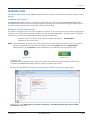
NNOTE: To find the Windows operating system version and the Service Pack level for the computer you are using, click the
Windows Start button. On the Start menu that displays, right-click Computer (Windows 7)/My Computer
(Windows XP) and select Properties. System information can be confirmed in the window that displays.
®
Windows 7 Start
Windows XP Start
MICROSOFT .NET
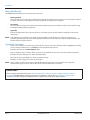
MICROSOFT.NET is required to run the software as designed. Most computers already have .NET installed. During
installation, the ORION Endpoint Utility software prompts you if .NET is not installed.
Windows XP: Install .NET from the software installation disc. The .NET file is shown in the example below.
Windows 7: Go to the Control Panel > Programs and Features > Turn Windows Features On> Microsoft .NET
Framework to enable .NET.
February 2015
ORI-UM-00019-EN-04
Page 5
Introduction
About this Manual
The ORION Endpoint Utility user manual has three main parts:
•
Getting Started
This part of the manual covers basic information including the equipment set up, how to start and exit the software
program, and how to set the COM ports for the equipment connected to the computer.
•
User Guide
The User Guide is the main part of the manual that includes step-by-step instructions and process details for using
the Endpoint Utility software application.
•
Appendix
Refer to the Appendix to find a glossary of terms used in this manual, and the software installation and removal
instructions.
NNOTE: To provide the best solution for our customers, Badger Meter continually improves software programs and
periodically updates this manual to reflect upgrades. Therefore, some discrepancies may be detected between the
installed software and this manual.
Typographic Conventions
•
Items on the software screens that you will be asked to select or choose by clicking a button, highlighting, checking
a box or another similar means are in bold text and capitalized in the manual.
Example: Click once on the View Report button.
•
Names of options, boxes, columns, fields, and sections are italicized. In most cases, first letters will be capitalized.
Example: The value displays in the Status Information field.
•
Messages and special markings are shown in quotation marks.
Examples: “Service Stopped” is shown on the display.
NNOTE: Names, addresses and other customer-related information displayed in screen examples were created for
demonstration purposes in this manual. No actual customer information is included.
IIMPORTAN
Before using the software for the first time, see "Removing Previous Software" on page 47 and "Installing the Software"
on page 49 in the Appendix for complete instructions on installing the software. Also see "COM Ports" on page 10 for
instructions on how to configure the COM ports for the equipment connected to the laptop computer.
Page 6
ORI-UM-00019-EN-04
February 2015
GETTING STARTED
GETTING STARTED
February 2015
ORI-UM-00019-EN-04
Page 7
Windows Updates
WINDOWS UPDATES
Make sure the laptop on which the software is installed always has all the most recent Windows updates. To check the laptop
for the most recent updates, perform the following steps.
Windows 7
Click the Windows Start button. Click All Programs> Windows Update. An update message displays in the window that
opens. Follow the instructions to install all updates if they are needed. Restart the laptop after making any updates.
Windows XP
Click the Windows Start button. Click Control Panel> Security Center. When the Security Center window opens, click
Automatic Updates. Then click the radio button for Automatic (recommended). Windows will automatically download
necessary updates to your laptop. Restart the laptop after making any updates.
NNOTE: An Internet connection is required to update the Windows operating system. See how to activate a wireless
connection for the Panasonic Toughbook below if you need help.
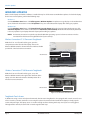
Wireless Connection CF-31 Panasonic Toughbook
With the CF-31 on a flat surface facing you, open the
compartment on the left side of the laptop. Access the
Wireless OFF/ON switch as shown. Move the switch to the ON
position for a wireless Internet connection.
OFF/ON Switch
Figure 1: CF-31 wireless OFF/ON switch
Wireless Connection CF-30 Panasonic Toughbook
With the CF-30 on a flat surface facing you, access the
Wireless OFF/ON switch on the right side in the front of the
laptop as shown. Move the switch to the ON position for a
wireless Internet connection.
OFF/ON Switch
Figure 2: CF-30 wireless OFF/ON switch
Toughbook Touch Screen
In addition to using a mouse or keyboard commands, the Panasonic Toughbook is also equipped with a touch screen for ease
of use. To make a selection, touch the screen using the stylus tool contained in the handle of the laptop or simply tap the
screen with your finger. The laptop screen is sensitive enough to allow selecting with a tap even if you are wearing gloves.
Throughout this manual, the term ”click“ is interchangeable with ”tap.“
Page 8
ORI-UM-00019-EN-04
February 2015
Equipment Setup
EQUIPMENT SETUP
IR Setup
IR programming cable
To use the software for IR applications, make sure to connect
the IR programming cable (PN: 64436-023) to the computer
serial port. If the computer does not have a serial port, you
can use a serial USB adapter.
Serial port
NNOTE: A serial USB adapter can be purchased at most
computer supply stores. Make sure to follow
manufacturer directions for using the adapter, and
install recommended drivers.
LAPTOP
IR head
RF Setup
Figure 3: IR programming cable attached at serial port
To use the software for RF applications:
•
Connect the magnetic mount antenna to the mobile transceiver and/or receiver.
•
Connect the ORION mobile transceiver and/or ORION mobile receiver to a DC power source and to the computer.
NNOTE: DC power is not needed if using a USB powered mobile transceiver.
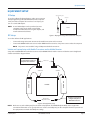
Vehicle and Laptop Setup with Mobile Transceiver and/or Mobile Receiver
Setup with an ORION ME FHSS mobile transceiver and/or ORION CE FHSS mobile receiver and the Panasonic Toughbook
should resemble the diagram below.
Place antenna on vehicle roof.
Keep antenna at least two feet
away from other antennas.
Two Feet +
USB Port
LAPTOP
Connect to
DC power source
ORION ME
ORION CE
Serial Port
DC power is not needed if
using the USB powered
ME mobile transceiver.
Figure 4: RF equipment setup
NNOTE: Make sure to set the COM port(s) for the attached equipment. The ORION Endpoint Utility stores equipment
connection information so it is good practice to use the same USB port(s) on the computer whenever you connect
the equipment to maintain the COM port settings.
February 2015
ORI-UM-00019-EN-04
Page 9
COM Ports
COM PORTS
Before using the software application, make sure the correct COM (communication) ports are set for any equipment
connected to the computer to establish communication with the software.
Check the COM Port(s)
Windows 7: Click Windows Start to open the menu. Right-click Computer and select Properties> Device Manager.
Windows XP: Click Windows Start to open the menu. Right-click Computer and select Properties> Hardware tab>
Device Manager.
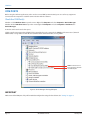
A window similar to the one below opens.
Click the small arrow next to Ports (COM & LPT) to expand the list. In the example, the ORION mobile transceiver ("Orion SE
Mobile COM") is using COM 5 and the IR cable ("Prolific USB-to-Serial Comm Port") is using COM 7.
ORION mobile transceiver
IR programming cable with
serial USB adapter
Figure 5: Device Manager showing COM ports
IIMPORTAN
Make a note of the COM ports. They will be needed to configure the settings for the software. See "Settings" on page 13.
Page 10
ORI-UM-00019-EN-04
February 2015
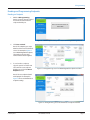
Software Startup/Exit
SOFTWARE STARTUP/EXIT
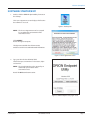
1. Double-click the ORION Endpoint Utility shortcut on
the desktop.
The License Agreement screen displays the first time
the software is accessed.
Figure 6: Desktop icon
NNOTE: The License Agreement must be accepted
by an authorized representative of the
customer/licensee.
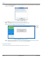
Click I ACCEPT.
Result: The login screen opens.
The login screen includes the software version,
and access to the license and trademarks information.
Figure 7: License Agreement screen
2. Type your ID in the User ID/Initials field.
The field accepts a maximum of 7 characters, alpha
and numeric.
NNOTE: The User ID/Initials must be entered by an
authorized representative of the
customer/licensee.
Result: The OK button becomes active.
Figure 8: ORION Endpoint Utility login screen
February 2015
ORI-UM-00019-EN-04
Page 11
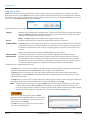
Settings
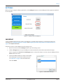
(Optional) Click View Trademarks to see a list of trademarked products. To close the Trademarks screen and return to
the login screen, click Close.
Figure 9: Trademarks screen
3. Click the OK button on the login screen to open the software application.
NNOTE: Click Cancel if you want to exit without opening the software application.
Result: The main screen is displayed as shown below. Login is complete.
Click the X
to exit the
software
application
Figure 10: ORION Endpoint Utility main screen
NNOTE: Remember to set the COM ports for any equipment attached to the computer before using the software
application for the first time. See "Settings" on page 13 for more information.
Exiting the Software
To close and exit the software application, click the X in the top right corner of any screen.
Page 12
ORI-UM-00019-EN-04
February 2015
Settings
SETTINGS
Before you begin using the software application, use the Settings function to set the COM ports for the equipment attached
to the computer.
Figure 11: Settings screen for COM ports
IIMPORTAN
If using an ORION mobile transceiver, make sure the ME driver is installed and the USB driver is configured according to the
instructions. See "Installing the ME Driver" on page 53 and "Configuring the USB Settings (Windows 7 and Windows XP)" on
page 61 for complete information.
Follow these steps to set the COM ports on the Setting screen.
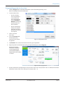
1. On the main menu, click the Settings button to open the Settings screen.
2. Click the Change button to open the COM port selection window for the hardware attached to the laptop.
For this example, the ORION ME RF COM Change button is selected. This button is used to select the COM port for the
ORION mobile transceiver.
3. Choose the COM port that was shown on the laptop
Device Manager screen for the mobile transceiver.
See "COM Ports" on page 10 for more information.
Then click Select.
Figure 12: ORION ME RF COM port
February 2015
ORI-UM-00019-EN-04
Page 13
Settings
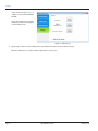
In the example shown in Figure 13,
“COM 5” is selected for ORION ME
RF COM.
Result: The window closes, and the
COM port you selected is displayed
on the Settings screen.
Figure 13: COM port set
4. Repeat steps 2 and 3 to set the COM port for any additional hardware connected to the laptop.
When the COM ports are set, the software application is ready to use.
Page 14
ORI-UM-00019-EN-04
February 2015
User Guide
USER GUIDE
February 2015
ORI-UM-00019-EN-04
Page 15
Main Screen
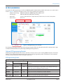
MAIN SCREEN
The software application main functions are listed in a menu on the left side of the software screens as shown in Figure 14.
Figure 14: Main screen
Main Functions
IR Programming
Used to read and program ORION water and gas endpoints using the IR programming cable,
including programming an endpoint following a tamper repair or retrofit installation (RTR water
installations only). With the optical head of the IR cable aligned to the endpoint IR LED port, click the
Press to Read button to use the IR Programming function. For additional information, see
"IR Programming" on page 17.
Quick Read
Used to perform an RF Quick Read on all ORION water and gas endpoints within range of the ORION
Endpoint Utility software using the RF mobile transceiver or receiver. Quick Read can also be used to
read a specific ORION endpoint serial number. See "Quick Read" on page 32.
Profile Extraction
Used to perform an IR or RF extraction of an ORION endpoint's historical interval profile data for
viewing in the ORION Profile Viewer software. See "Profile Extraction" on page 37.
Settings
Used to set or change the COM ports for the devices connected to the computer. See "Settings" on
page 13.
Navigating the ORION Endpoint Utility Software
The main function buttons are always displayed in the left column as shown above. A button is green when selected.
Click the X at the top right corner of the screen to close and exit the software application.
Page 16
ORI-UM-00019-EN-04
February 2015
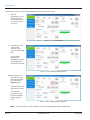
IR Programming
IR PROGRAMMING
An example of an IR Programming screen for an ORION Migratable endpoint with an HR-E® LCD encoder on a water meter is
shown in Figure 15. The fields and buttons on the screen vary depending on the following:
•
Endpoint technology:
ORION Fixed Network, ORION Migratable, ORION Classic
•
Encoder type:
HR-E LCD, HR-E, ENC (ADE®), RTR®, Permalog
•
Meter type:
E-Series®, Recordall® Disc, Compound Series, Turbo Series, Fire Series, Fire Hydrant
•
Meter service:
Water, Gas
Endpoint Technology
Encoder Type
Figure 15: IR Programming screen with data
Meter Type
The endpoint technology, encoder type and meter type, together, define the information that will be displayed in the Type
and Meter Information fields when performing the IR Programming functions.
Optional IR Programming Bracket
An IR Programming Bracket (PN: 65917-001) is available and can be used to assist in reading ORION endpoints. The bracket
facilitates correct alignment between the IR optical read head of the programming cable and the IR port on the endpoint,
ensuring a steady read position while leaving your hands free.
IR Programming Fields
Endpoint/Encoder Information, Reading, Radio Status
Displays For
Field Label
Description
Endpoint Technology
Encoder Type
S/N
ME, SE, CE
All
Endpoint serial number.
Type
ME, SE, CE
All
Endpoint and encoder type. For gas meters, ”Gas“ displays in the Type
field. If ”Gas“ does not display, the meter is water.
Firmware
ME, SE
All
Endpoint firmware version.
Current*
ME, SE, CE
All
Displays the current reading for the selected endpoint.
ME, SE
All
Displays the time-synchronized daily endpoint reading value.
ME, SE, CE
All
Displays the current radio status of the endpoint.
Daily*
Radio Status
* The reading value is the raw read without reading resolution applied.
February 2015
ORI-UM-00019-EN-04
Page 17
IR Programming
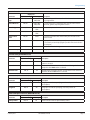
Status Indicators
Box is checked when an alert is reported. The status fields that display depend on the encoder and endpoint type.
Displays For
Field Label
Description
Endpoint Technology
Encoder Type
Cover Removal
ME, SE
Gas
Encoder Empty Pipe
ME, SE
ELCD
E-Series meter is reporting a no flow condition in the pipe.
Encoder End of Life
ME, SE
ELCD
Encoder or E-Series meter is reporting to the endpoint that the
encoder battery life indicator has been activated.
Encoder Error
ME, SE
ELCD,
HR-E, ENC,
Endpoint is reporting a potential gas meter index cover tamper.
Encoder is reporting a device error to the endpoint.
Permalog
Encoder
Programmed
ME, SE
ELCD
Encoder or E-Series meter is reporting to the endpoint that it
has been reprogrammed via IR.
Encoder Removal
ME, SE
ELCD
Encoder is reporting a removal condition to the endpoint.
Encoder Tamper
ME, SE
ELCD
Encoder is reporting a tamper condition.
Encoder Temp
ME, SE
ELCD
Encoder or E-Series meter is reporting to the endpoint that it
senses temperatures outside the specified range.
Endpoint
Programmed
ME, SE
All
Index Changed
ME, SE
RTR and Gas
Leak
ME, SE, CE
Endpoint was programmed via IR.
Endpoint is reporting that the reading (odometer setting)
was changed.
HR-E, ENC,
Endpoint is reporting a potential leak condition.
RTR, Permalog
ELCD
Encoder or E-Series meter is reporting a potential leak condition
to the endpoint.
Low Battery
ME, SE
All
Endpoint is reporting a low battery.
Mobile Mode
ME, SE
All
Endpoint is communicating in mobile mode.
ME, SE, CE
HR-E, ENC,
RTR and Gas
Endpoint is reporting a no usage condition.
No Usage
ELCD
Reverse Flow
Sensor Error
Tamper
ME, SE, CE
ME, SE
ME, SE, CE
HR-E, ENC
and Gas
Encoder or E-Series meter is reporting a potential no usage
condition to the endpoint.
Endpoint is reporting a reverse flow condition.
ELCD
Encoder or E-Series meter is reporting a reverse flow condition
to the endpoint.
ELCD
E-Series only. Meter is reporting a sensor error or meter alarm
other than empty pipe or low temp.
ELCD, HR-E, Endpoint is reporting a tamper. This condition occurs when the
ENC, RTR,
wire between the encoder and the endpoint is cut or shorted, or
Permalog and the encoder is not connected.
Gas remotes
NNOTE: For more information about status indicators, refer to the following documents, available at www.badgermeter.com:
•
•
•
Page 18
HR-E, ENC and RTR: Refer to the ORION Water Endpoint Product Data Sheet for the endpoint type.
HR-E LCD: Refer to the HR-E LCD Encoder User Manual.
E-Series: Refer to the E-Series Ultrasonic Meters User Manuals.
ORI-UM-00019-EN-04
February 2015
IR Programming
Meter Information
Displays For
Field Label
Endpoint Technology
Encoder Type
Description
Meter Size and
Type
ME, SE
ELCD, HR-E,
ENC, RTR
The size and type of the meter for which the encoder
was programmed.
Unit of Measure
ME, SE
ELCD, HR-E,
ENC, RTR
The unit of measure as defined by the encoder: cubic meters,
cubic feet, gallons, imperial gallons or liters.
Encoder Type
ME, SE
ELCD, HR-E,
ENC
The encoder protocol.
Dials
ME, SE
ELCD, HR-E,
ENC
The encoder dial resolution as reported from the encoder.
Reverse Flow
Total
ME, SE
ELCD
ME, SE, CE
Gas
Displays after initial read for gas endpoints only. Provides access
to a read-only screen displaying the possible drive circles for the
gas endpoint.
ME, SE
Gas
The direction for the drive gear.
ME, SE, CE
Gas
The gas pressure factor.
Drive Circle
Direction
Pressure Comp
The total reverse flow units measured by the encoder or the
E-Series meter.
Flow Rate Study (ORION ME and SE)
Displays For
Field Label
Description
Endpoint Technology
Encoder Type
Start Date Time
ME, SE
All
Date and time the Flow Rate Study was started. Fills when Get
button is selected.
Intervals
ME, SE
All
The number of five-minute Intervals collected during the Flow Rate
Study. Fills when Get button is selected.
Min Max Total
ME, SE
All
The Minimum and Maximum flow, and the Total counts collected.
The fields fill when Get button is selected.
GPS Location (ORION ME and SE)
Displays For
Field Label
Description
Endpoint Technology
Encoder Type
Latitude
ME, SE
All
Geographic coordinate specifying north-south position of
the endpoint.
Longitude
ME, SE
All
Geographic coordinate specifying east-west position of
the endpoint.
Advanced Endpoint Functions (ORION ME and SE)
Displays For
Field Label
Battery Status
February 2015
Endpoint Technology
Encoder Type
ME, SE
All
Description
Visual indicator of the endpoint battery status.
ORI-UM-00019-EN-04
Page 19
IR Programming
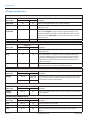
IR Programming Buttons
Reading
Displays For
Button Label
Endpoint Technology
Encoder Type
Description
Quick Read
All
All
Initiates an RF Quick Read for the selected endpoint.
High Power
CE
All
Forces a brief high powered signal from the endpoint to a
gateway receiver.
Program/
Force Read
All
All
Toggles, based on the encoder type. For ORION water endpoints
with an RTR, Program is used to set the endpoint odometer value
following a tamper repair. With an ADE or HR-E LCD encoder or with
an E-Series meter, Force Read is used to view the real-time encoder
odometer value.
Read Endpoint
All
All
Initiates IR communication between the software and the endpoint.
Radio Status
Displays For
Button Label
Description
Endpoint Technology
Encoder Type
Start
All
All
Starts endpoint radio. "On-Mobile Mode" is shown in the
Radio Status field.
Stop
All
All
Stops endpoint radio. "Stopped" is shown in the Radio Status field.
A stopped endpoint must be reprogrammed to begin transmitting
again. With an ORION Migratable or Fixed Network endpoint, the
endpoint historical interval data (profile data) is cleared when the
endpoint is restarted.
Pause
All
All
Pauses endpoint transmission temporarily until a unit of water or gas
is registered. "Paused" is shown in the Radio Status field.
Meter Information
Displays For
Button Label
Change
Endpoint Technology
Encoder Type
Description
ME, SE
HR-E, ENC,
RTR, Gas
CE
Gas
For water meters, used to change the meter size, type and/or units of
measure. For gas meters, used to change the drive circle (units, dials
and resolution), pressure and direction.
GPS Location (ORION ME and SE)
Displays For
Button Label
Set GPS
Location
Endpoint Technology
Encoder Type
ME, SE
All
Description
Brings up a window in which you can enter the latitude and longitude
for the endpoint.
Flow Rate Study (ORION ME and SE)
Displays For
Button Label
Description
Endpoint Technology
Encoder Type
Start
ME, SE
All
Used to start the flow rate study.
Get
ME, SE
All
Used to get the results of the flow rate study.
Save
ME, SE
All
Used to save the flow rate study results. Displays where the file
is saved.
Page 20
ORI-UM-00019-EN-04
February 2015
IR Programming
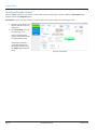
Reading and Programming Endpoints
Reading an Endpoint
1. With the IR Programming
button selected, align the optical
head of the IR cable with the
endpoint IR LED port.
Figure 16: ORION Endpoint Utility main screen with IR Programming selected
2. Click Press to Read.
Result: The endpoint type, meter
details and the current read fill the
screen. The example in Figure 17
is an ORION Migratable endpoint.
The reading is the raw value
without read resolution applied.
3. To read another endpoint,
align the optical head of the IR
cable with the next endpoint
IR LED port and click the Read
Endpoint button.
Figure 17: IR Programming screen for ORION Migratable endpoint with HR-E
Result: The new endpoint details
are displayed. The example In
Figure 18 shows an ORION Classic
endpoint reading.
Figure 18: IR Programming screen for ORION Classic endpoint with ENC
February 2015
ORI-UM-00019-EN-04
Page 21
IR Programming
Stop, Pause, Start
ORION water endpoints are programmed at the factory to begin sending meter readings when the register senses flow
through the meter. As a result, ORION endpoints can be installed on meters without having to manually start the endpoint.
Once water usage has been registered on the meter, the endpoint sends a signal every four seconds (ORION Classic) or every
five to six seconds (ORION Migratable and Fixed Network).
The following statuses may display in the Radio Status field on the IR Programming screen.
Stopped
Endpoint is not transmitting. The endpoint radio is stopped and must be started to begin transmitting
again. For ORION Migratable and Fixed Network endpoints, any stored historical interval data (profile
data) will be cleared when the endpoint is restarted.
NNOTE: An ORION endpoint with an RTR must be programmed to restart.
Paused
Endpoint radio transmission is temporarily stopped until water flow is registered.
On Mobile Mode
ORION Migratable and Fixed Network: Endpoint is sending/receiving communications in mobile radio
mode until and unless the endpoint establishes communication and is assigned to a network gateway.
An endpoint in mobile mode sends a message requesting gateway assignment as frequently as once
an hour.*
ORION Classic: Endpoint always displays On Mobile Mode when transmitting.
Discovery Mode
For troubleshooting only. To be used under the direction of Badger Meter Technical Support.
On-Fixed Mode
Endpoint is assigned to a network gateway for fixed network data collection. Endpoints in network
On-Fixed Mode can also be received by the mobile transceiver.* An endpoint will revert to On Mobile
Mode if it fails to receive a response from a gateway for four consecutive days. Once communication is
re-established with the gateway, the endpoint automatically transitions to On-Fixed Mode.
* Depending on the endpoint firmware version.
•
The Start button is used to start an endpoint radio before usage is registered. Align the optical head of the IR cable
with the endpoint IR LED port and tap Start. Radio Status changes to ”On Mobile Mode.“
•
The Pause button is used to pause the radio signal temporarily. Align the optical head of the IR cable with the
endpoint IR LED port and tap Pause. The endpoint radio begins transmitting again when a unit of water or gas is
registered from the meter.
•
The Stop button is used to stop an endpoint radio from sending a signal, regardless of the usage registered from the
meter. Align the optical head of the IR cable with the endpoint IR LED port and tap Stop.
NNOTE: Stopped radios must be restarted using the Start function and will not automatically restart when usage
is registered by the meter. When ORION ME or SE endpoints are used with an RTR, the odometer value
must also be programmed to reflect the current registration reading. When used with E-LCD, HR-E and ADE
encoders or E-Series meters, the odometer value is automatically updated within the hour.
The historical interval data (profile data) of ORION
Migratable and Fixed Network endpoints is cleared when
the endpoint is restarted. The message shown in Figure 19
displays when you click Stop.
Click Yes if you are sure you want to stop the endpoint
and clear the endpoint history.
Figure 19: Profile data warning message
Page 22
ORI-UM-00019-EN-04
February 2015
IR Programming
Programming an RTR Endpoint to the Odometer Setting
To install an ORION endpoint on an active meter with usage on an RTR, use the following information to ensure that the value
in the endpoint matches the current odometer value on the RTR once the endpoint is connected to the RTR.
With an RTR, you must also program and set the endpoint to the RTR odometer value following a tamper repair.
NNOTE: An ORION endpoint connected to an ADE, E-LCD or approved competitive three-wire encoder or an ADE or High
Resolution E-Series Ultrasonic meter does not require programming to clear a tamper. After the wires have been
repaired, the endpoint is automatically updated to reflect the register odometer value in the first hour after the wires
have been repaired.
IIMPORTAN
Stopping an endpoint suspends data profiling. Restarting clears all historical interval data (profile data) and places fixed mode
endpoints into mobile mode. Endpoints in mobile mode may not revert to fixed mode for up to 48 hours.
Reading the Odometer
To install an ORION Migratable endpoint on an active meter with usage on the RTR, use the following information to ensure
that the value in the endpoint matches the current odometer value on the RTR once the endpoint is connected to the RTR.
When programming ORION endpoints, enter the value of the six
moveable odometer wheels plus the sweep hand for all meter types
(gallons, cubic feet, etc.) and all meter models.
In the example shown, the odometer value in the moveable dials
(both white and black digits) is ”000001.“
The sweep hand is pointing between the ”6“ and the “7“ but because
the sweep hand has not yet hit the ”7“, use ”6“ as the value for the last
digit of the meter reading. In this example, the value to be entered
into the ORION endpoint Current Reading field would be ”16“or
”0000016.“ (The leading zeros are not required.)
Figure 20: RTR odometer
When programming an ORION endpoint connected to an E-Series
meter with an RTR protocol, program the seven most significant (left
most) digits shown on the meter display.
Figure 21: E-Series meter display
February 2015
ORI-UM-00019-EN-04
Page 23
IR Programming
Follow this procedure for programming an RTR endpoint to the odometer setting.
1. On the IR
programming screen,
double-click in the
Current Reading field
to select the current
read value.
Figure 22: Current Reading field
2. Using the keyboard,
enter the RTR
odometer value
in the Current Reading
field.
Result: The field
background is
highlighted to indicate
an unprogrammed
value has been entered.
Figure 23: Current Reading field highlighted
Align the optical head
of the IR cable with
the endpoint IR LED
port and click the
Program button.
Hold the optical head
of the IR cable steady.
The endpoint is
programmed when
the Current Reading
field background
clears.
Figure 24: Current Reading field programmed
NNOTE: The Status Indicators are also updated to show Index Changed and Endpoint Programmed.
Page 24
ORI-UM-00019-EN-04
February 2015
IR Programming
Programming Water Meter Type, Size and Units of Measure (ORION ME/SE)
To program the water meter type and size for an RTR or ADE, follow these steps.
NNOTE: The water meter type, size and units of measure for endpoints connected to an HR-E or ELCD encoder type are
obtained from the encoder and are not programmable.
1. Align the optical head of the
IR cable with the endpoint
IR LED port.
2. Click Read Endpoint
if a reading is not
already registered.
3. Click the Change button
in the Meter Information
section of the screen.
Result: The Change Meter
Information window opens.
Figure 25: Change button
4. Scroll through the list
and click to select the
appropriate Meter Size And
Type and Unit Of Measure.
5. Align the optical head of the
IR cable with the endpoint
IR LED port and click
Program.
Result: New Meter
Information is displayed on
the IR Programming screen
as shown (Figure 27). The
Status Indicators are also
updated to show Endpoint
Programmed.
Figure 26: Meter Size, Type, Unit of Measure
Figure 27: Meter Type, Size, Unit of Measure programmed
NNOTE: For gas meters, see "Programming Gas Endpoints" on page 27.
February 2015
ORI-UM-00019-EN-04
Page 25
IR Programming
Force Read (Encoder Output)
When an ORION endpoint is connected to a device with encoder output (high resolution or ADE), the Force Read button
displays instead of the Program button.
Force Read is used to view the real-time encoder odometer value and to verify a successful tamper repair.
1. Align the optical head of the
IR cable with the endpoint
IR LED port.
2. Click Force Read on the IR
Programming screen.
Result: The reading value
updates to reflect the current
encoder odometer value.
If the tamper condition is
successfully repaired and
the tamper no longer exists,
the Tamper Status Indicator
clears.
Page 26
Figure 28: Force Read
ORI-UM-00019-EN-04
February 2015
IR Programming
Programming Gas Endpoints
The procedure below is for programming an ORION Migratable/Fixed Network gas endpoint. Perform the same steps for
an ORION Classic gas endpoint. For a description of the fields and buttons on the screens, see "IR Programming Fields" on
page 17 and "IR Programming Buttons" on page 20.
Program a Read for a Gas Endpoint
1. From the main
menu, click
IR Programming.
2. Align the optical head
of the IR cable with
the gas endpoint IR
LED port.
3. Click the Press to
Read button.
Result: The IR
Programming
screen displays for
the endpoint.
Figure 29: Main menu
4. On the IR
programming screen,
double-click in the
Current Reading field
to select the current
read value.
Figure 30: IR Programming screen for gas endpoint
February 2015
ORI-UM-00019-EN-04
Page 27
IR Programming
5. Using the keyboard,
enter the new value
in the Current Reading
field.
Result: The field
background is
highlighted to indicate
an unprogrammed
value has been entered.
Figure 31: Current Reading field highlighted
Align the optical head
of the IR cable with
the endpoint IR LED
port and click the
Program button.
Hold the optical head
of the IR cable steady.
The highlighted
background in the
Current Reading field
is cleared when the
endpoint read is
programmed.
Figure 32: Current Reading field clears when programmed
6. Visually verify that the anticipated index reading is reflected in the Current Reading field. If it is not, repeat steps 4…6.
Page 28
ORI-UM-00019-EN-04
February 2015
IR Programming
Change and Program the Gas Drive Circle
1. Click the Change button in the Meter Information section of the IR Programming screen.
Result: The Change Drive Circle window opens.
2. Locate the Drive Circle.
•
Use the selections
in the top half of the
screen to filter the
list on the bottom by
choosing Integral or
Remote, and choosing
the Units, Dials and
Res (resolution).
•
Or just scroll through
the list in the bottom
half of the window to
find the drive circle for
the endpoint.
3. Click to select the
drive circle.
4. Tap in the Pressure field.
Use the keyboard to
enter the pressure factor,
if applicable.
Figure 33: Change Drive Circle
5. Tap Direction. Then select the direction for the drive gear, if applicable.
6. Align the optical head of the IR cable with gas endpoint IR LED port and click Program.
Result: The new Meter
Information is displayed
on the IR Programming
screen and the Endpoint
Programmed Status Indicator
is selected.
Figure 34: Meter programmed
7. Visually verify that the anticipated drive circle, direction and pressure compensation values are reflected in the Meter
Information section of the screen. If they are not, repeat steps 1…6.
February 2015
ORI-UM-00019-EN-04
Page 29
IR Programming
GPS Location (ORION ME/SE)
If the latitude and longitude are not set or need to be changed, you can set them manually for any ORION Migratable or Fixed
Network (in mobile mode) endpoint.
1. Click the Set GPS Location button in the GPS Location section of the IR Programming screen.
Result: The GPS Input window opens.
2. Enter the Latitude and Longitude in each field, respectively.
NNOTE: The field will only accept numeric characters, decimal point (period) and minus sign (–).
Figure 35: GPS Location
3. Align the optical head of the IR cable with the endpoint IR LED port and click OK.
Result: The GPS Input window closes and the Latitude and Longitude you entered display on the IR Programming screen.
Figure 36: GPS Location set
Page 30
ORI-UM-00019-EN-04
February 2015
IR Programming
Flow Rate Study (ORION ME/SE)
A flow rate study is a week-long study that can be performed on an ORION Migratable or Fixed Network (in mobile mode)
endpoint to report high, low and average flow rates.
A flow rate study can also be requested on the Advanced Endpoint Details screen available via the Quick Read screen.
Starting a Flow Rate Study
With the optical head of the IR cable aligned with the endpoint IR LED port, tap the Start button in the Flow Rate Study section
of the IR Programming screen.
Result: A message window opens to confirm the successful start of the flow rate study. The study continues for one week from the
start time and date.
Figure 38: Flow Rate Study started
Figure 37: Start Flow Rate Study
Getting Flow Rate Study Results
1. At the end of a week-long flow rate study, align the optical head of the IR cable with the endpoint IR LED port and tap
the Get button in the Flow Rate Study section of the IR Programming screen.
Result: The data from the study fills in the field next to the Start, Get and Save buttons as shown. The flow study data
includes the minimum, maximum and total usage for the week.
Figure 40: Flow Rate Study results saved
Figure 39: Flow Rate Study results
2. Tap the Save button to create a file of the flow rate study data.
Result: A screen display showing the location of the saved file.
3. Tap OK to close the window.
February 2015
ORI-UM-00019-EN-04
Page 31
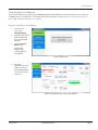
Quick Read
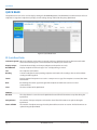
QUICK READ
The Quick Read screen can be used to display readings for all ORION Migratable, Fixed Network (in mobile mode) and Classic
endpoints in range. One endpoint may display several readings during an RF (radio frequency) Quick Read.
Figure 41: Quick Read screen
RF Quick Read Fields
Limit to Single S/N When an endpoint serial number is entered, performs a Quick Read on the endpoint entered via RF.
Click in the field and type the serial number for the endpoint you want to read.
Display Unique
Check the box to display each unique endpoint serial number once only.
Read Method
Displays endpoint and encoder type. ”Gas“ is displayed for gas meters.
S/N
The endpoint serial number.
Reading
Current reading for the corresponding endpoint serial number. The reading is the raw value without
reading resolution applied.
Status
Displays potential exception issues such as a tamper or no usage. If no exceptions are noted, the Status
field is blank.
RSSI
Bar showing the relative signal strength of the endpoint to mobile transceiver or receiver
communication.
Time
The date and time of the Quick Read.
Statistics
Duration
The elapsed time in seconds since the Quick Read started. This field continues to update during the
Quick Read.
Unique Count
The number of unique endpoint serial numbers heard. This field continues to update during the
Quick Read.
Count - All MM
The number of endpoint messages heard by the mobile transceiver or receiver. This field continues to
update during the Quick Read.
Page 32
ORI-UM-00019-EN-04
February 2015
Quick Read
RF Quick Read Buttons
ORION ME
Click ORION ME to Quick Read all ORION Migratable or Fixed Network (in mobile mode) endpoints
within range. Click again to stop reading.
ORION CE
Click ORION CE to Quick Read all ORION Classic endpoints within range. Click again to stop reading.
Clear Grid
Removes the current grid display and refreshes the screen so you can change selections. The Statistics
field clears and restarts with the next Quick Read.
View Advanced
Endpoint Details
Provides additional information which has been programmed into an ORION Migratable or Fixed
Network endpoint. Select an endpoint in the grid before clicking the button.
Save
Saves the Quick Read in the grid as a .csv file. Window opens to show where and when the file is saved.
NNOTE: When performing the procedures described in this section, make sure the equipment for the endpoints you are
reading is connected to the laptop, and the COM ports are set correctly. See "Equipment Setup" on page 9 and
"COM Ports" on page 10 if you need help.
February 2015
ORI-UM-00019-EN-04
Page 33
Quick Read
RF Quick Read - All Endpoints
The example below is for ORION Migratable or Fixed Network (in mobile mode) endpoints. If you are reading ORION Classic
endpoints, perform the same steps using the ORION CE button.
NNOTE: To read both ORION Migratable and ORION Classic endpoints simultaneously, see "Changing Quick Read Technology"
on page 35.
1. Click Quick Read on the main menu.
2. Click the ORION ME button to start.
Result: The ORION ME button becomes green to indicate communication with the endpoints.
The fields on the screen begin to fill with readings and the Statistics section changes to reflect the elapsed time and number
of readings.
Figure 42: ORION ME Quick Read
3. Click the ORION ME button again to pause or stop the Quick Read.
Result: The button becomes clear and the readings stop.
For a single endpoint read:
4. To view readings for a single endpoint serial number, click the row of the endpoint you want to read.
Result: The endpoint serial number fills in the Limit to Single S/N field.
5. Click the ORION ME button again.
Result: The button becomes green and the readings that are displayed are for the single endpoint serial number
you selected.
6. Click the ORION ME button again to stop the Quick Read.
Page 34
ORI-UM-00019-EN-04
February 2015
Quick Read
Changing Quick Read Technology
When reading both ORION Migratable (or Fixed Network in mobile mode) and ORION Classic endpoints, you can quickly
change from one technology to the other and back again, or listen simultaneously.
NNOTE: Make sure the mobile transceiver and mobile receiver are connected. For help, see "Vehicle and Laptop Setup with
Mobile Transceiver and/or Mobile Receiver" on page 9.
Steps 1...4 of the following procedure describes changing from an ORION ME Quick Read to an ORION CE Quick Read.
The same steps can be performed to change from an ORION CE Quick Read to an ORION ME Quick Read by selecting the
opposite buttons.
1. After performing a Quick Read, click the ORION ME button to stop the read.
Result: The button becomes clear and the readings stop.
2. Click Clear Grid to clear the Quick Read screen.
3. Click the ORION CE button to start a Quick Read of all ORION Classic endpoints.
4. Click the ORION CE button again to stop the Quick Read.
To read ORION Migratable and ORION Classic endpoints simultaneously:
5. Click Clear Grid to clear the Quick Read screen.
6. Click the ORION ME button and the ORION CE button.
Result: Readings for both ORION Migratable and Classic endpoints are displayed in the grid.
7. Click the ORION ME and ORION CE buttons again to stop the Quick Read.
RF Quick Read - Single Endpoint
1. Click the Quick Read button on the main menu.
2. Click in the Limit to Single S/N field and use the keyboard to enter the serial number of the endpoint you want to read.
Figure 43: RF Quick Read screen
3. Click the button for the endpoint type. In the example above, an ORION Migratable endpoint serial number is
entered so you would click the ORION ME button to start.
Result: Readings from the endpoint fill in the fields of the screen and the View Advanced Endpoint Details button
becomes active for an ORION Migratable endpoint.
4. Click the endpoint button again to stop the reading.
February 2015
ORI-UM-00019-EN-04
Page 35
Quick Read
Advanced Endpoint Details (ORION ME/SE)
The View Advanced Endpoint Details button on the Quick Read screen becomes active when a single ORION Migratable or
Fixed Network endpoint is being read via RF. Select this button to access the options described below.
Figure 44: Advanced Endpoint Details screen
NNOTE: The options described here are also available for ORION Migratable and Fixed Network endpoints via IR from the IR
Programming screen.
Firmware Version
Click Get to display the endpoint firmware version in the field.
GPS Location
Click Get to display the latitude/longitude for the endpoint if the location has been programmed.
Flow Rate Study
The field displays the flow study results.
•
Start
Click to start a 7-day flow rate study.
•
Get
Click to get the results from the flow rate study.
•
Save
Click to save the flow rate study results.
Get Extended
Status Data
Click to receive and display the full endpoint status which includes meter size, model type and units,
as well as any status alerts.
Close
Click to close the Advanced Endpoint Details screen.
Page 36
ORI-UM-00019-EN-04
February 2015
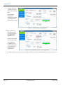
Profile Extraction
PROFILE EXTRACTION
The Profile Extraction option on the main menu is used to extract, save and view historical interval profile data from ORION
Migratable (or Fixed Network in mobile mode) and ORION Classic water and gas endpoints.
NNOTE: Extracting historical interval profile data from an ORION Migratable endpoint can be performed via IR or RF.
Extracting historical interval profile data from an ORION Classic endpoint can only be performed via IR.
Figure 45: Profile Extraction screen
Profile Extraction Screen
IMPORT
The IMPORT button opens Windows File Explorer for access to saved profile data .csv files. Files
can be added to the C:\Program Data\Badger Meter\ORION folder and will display in the Select To
View list. For additional information, see "Adding Profile Data Files" on page 44.
Select To View
Profile data files that are saved to the C:\Program Data\Badger Meter\ORION folder will display
in the Select To View list by endpoint number. If there are no profile data files to view, “No Data
Available“ displays in the field.
IR (CE or ME)
Select the IR radio button to extract profile data from an ORION CE or ME endpoint using the IR
cable. An IR programming cable must be attached to the laptop. See "IR Setup" on page 9.
RF (ME Only)
Select the RF radio button to extract profile data from an ORION ME endpoint using radio
frequency (RF). An ORION ME transceiver and antenna must be attached to the laptop. See "RF
Setup" on page 9 for more information.
Initial Read
Select the Initial Read button to read the endpoint and start the profile extraction process.
Interval Readings
An ORION ME water endpoint stores 90 days of hourly readings or 22 days of readings taken at 15 minute intervals. The
chart below shows the number of readings collected for meters set at 60 minute (hourly) intervals and at 15 minute (quarter
hourly) intervals:
Available Profile Data
Extraction Intervals
Hourly Reads:
1 Read per Hour
24 Reads per Day
15 Minute Reads:
4 Reads per Hour
96 Reads per Day
7 days
168 reads (24 x 7)
672 (96 x 7)
14 days
336 reads (24 x 14)
1344 (96 x 14)
30 days
720 reads (24 x 30)
2160 (96 x 22.5)
60 days
1440 reads (24 x 60)
2160 (96 x 22.5)
All/90 days
2160 reads (24 x 90)
2160 reads (96 x 22.5)
An ORION CE endpoint is capable of storing more than 20,000 historical interval readings.
February 2015
ORI-UM-00019-EN-04
Page 37
Profile Extraction
IR Profile Extraction
To access profile data from an ORION endpoint using IR, follow these steps.
1. Click to select the IR (CE or ME) radio button.
Figure 46: IR profile extraction
2. With the IR cable connected to the laptop, align the optical head of the IR cable with the endpoint IR LED port.
3. Click Initial Read. Hold the IR cable steady while the data is being read.
4. On the window that displays, select the appropriate meter size and unit of measure. For water endpoints, the Test
Circle window will display. For gas endpoints, the Drive Circle window will display. An example of both windows is
shown (Figure 47, Figure 48).
Result: The endpoint serial number displays on the screen along with the encoder type, meter type and size.
Figure 47: Water - Test Circle selection
Figure 48: Gas - Drive Circle selection
5. Choose the number of days of historical interval data to extract using the drop-down menu.
Choose number of days
Figure 49: Choose number of days for profile extraction
Page 38
ORI-UM-00019-EN-04
February 2015
Profile Extraction
6. Click the Read Data button. Hold the IR cable steady while the data is being read.
Result: A progress bar displays while data is being extracted. The screen fills as shown below when the data has
been retrieved.
Figure 50: IR profile extraction complete
IR Profile Extraction Details
Oldest Reading
The date and time of the oldest reading in the data extracted.
Newest Reading
The date and time of the newest reading in the data extracted.
Interval
The reading interval at which the endpoint is set: 60 Minutes or 15 Minutes
Quantity
The number of interval reads retrieved.
Status Indicators
Potential exception issues such as a tamper or no usage. If no exceptions are noted, none of
the boxes are checked.
7. Use the buttons to Save Data or Clear Data. You can also select Change Interval to change the time between
historical interval meter readings.
Save Data
Select to save the profile data. A window displays with a message that confirms the save and
the location of the file as shown in Figure 51. Click OK to close the window.
NNOTE: The endpoint number of the saved file now displays in the Select To View field on
the screen.
Figure 51: Save file confirmation
Change Interval
Select to change the interval (60 minutes or 15 minutes) for meter readings. Changing the
interval clears any stored interval data. A window opens, asking you to confirm the change.
Clear Data
Select to clear all historical interval profile data from the endpoint. A window opens, asking you
to confirm the change.
8. IR data profile extraction is complete. To access profile data for another endpoint, repeat steps 2…7.
February 2015
ORI-UM-00019-EN-04
Page 39
Profile Extraction
RF Profile Extraction (ORION ME/SE)
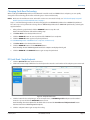
To access profile data for an ORION Migratable (or Fixed Network in mobile mode) endpoint using RF, follow these steps.
1. Click to select the RF (ME only) radio button.
2. Click in the S/N field and use the keyboard to enter the serial number of the endpoint.
Result: As the radio connection is made, you will see two status messages: "Waiting For Mobile Message" and then
"Waiting for Extended Status."
Figure 52: RF profile extraction
3. On the window that displays, select the appropriate meter size and unit of measure. For water endpoints, the Test
Circle window will display. For gas endpoints, the Drive Circle selection window will display. An example of both
windows is shown (Figure 53, Figure 54).
Figure 53: Water - Test Circle selection
Figure 54: Gas - Drive Circle selection
4. Choose the number of days of historical interval data to extract using the drop-down menu.
Choose number of days
Figure 55: Choose number of days for profile extraction
5. Then click Read Data.
Page 40
ORI-UM-00019-EN-04
February 2015
Profile Extraction
Result: Two status messages display: "Waiting for Mobile Configuration" and then "Reading Data." A bar displays to show
progress. Profile data for the endpoint is extracted and the screen fills as shown below to confirm that the data has
been retrieved.
Figure 56: RF profile extraction complete
RF Profile Extraction Details
Oldest Reading
The date and time of the oldest reading in the data extracted.
Newest Reading
The date and time of the newest reading in the data extracted.
Interval
The reading interval at which the endpoint is set: 60 Minutes or 15 Minutes.
Quantity
Displays the number of interval reads retrieved.
Status Indicators
Displays potential exception issues such as a tamper or no usage. If no exceptions are noted,
none of the boxes are checked.
6. Click the button to Save Data. You can also click Change Interval to change the time between historical interval
meter readings.
Save Data
Click to save the profile data. A window displays with a message that confirms the save and the
location of the file (Figure 57). Click OK to close the window.
NNOTE: You must click Save Data to save the file and make it accessible in the
Select To View list.
Figure 57: Save file confirmation
Change Interval
Click to change the interval (60 minutes or 15 minutes) for meter readings. Changing the
interval clears any stored interval data. A window opens, asking you to confirm the change.
7. The RF Profile Extraction is complete. To read another endpoint, repeat steps 2…6.
February 2015
ORI-UM-00019-EN-04
Page 41
Profile Extraction
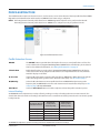
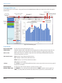
Viewing Profile Data
Saved profile data can be viewed in a bar graph format in the ORION Endpoint Utility. An example of a profile data graph is
shown below.
PRINT the graph
List of saved
endpoint profile
data files
Click to return to Profile
Extraction screen
Units of measure
(if available)
Click + to
expand
and see
files
IMPORT a profile
data file
To see consumption data,
hover over the graph with the
mouse
SAVE profile data -file must
be checked in the Select To
View list
Endpoint serial
number and date
of profile data
Click check box
to save file
Figure 58: Profile data graph
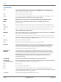
Graph Details
Extract Profile Data
Click to return to the Profile Extraction screen.
Select To View
Endpoint numbers with saved profile data are displayed in ascending numerical order. Click + to
display saved files for the endpoint. Then click a file to display a bar graph of the profile data.
Units (Y-axis)
When unit of measure is available, a drop-down menu will display. Select from the drop-down
menu to change the Y-axis value.
Time Period (X-axis)
Hour: Displays a day of data, divided into hours.
Day: Displays a month of data, divided into days.
Month: Displays a year of data, divided into months.
Year: Displays a year of data.
<Today>
Click Today to see a graph of the profile data for the current day. Use the arrows to view a graph of
the previous or next day.
Date Drop-Down
Click the drop-down arrow to display a calendar and select a date.
IMPORT, PRINT, SAVE
Use IMPORT to access and import a profile data file. Use PRINT to print the current graph. Use
SAVE to save the profile data. The file in the Select To View list must have a check mark to save.
Page 42
ORI-UM-00019-EN-04
February 2015
Profile Extraction
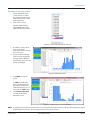
Procedure for Viewing a Graph
1. On the Profile Extraction
screen, click the + next to
the endpoint number in the
Select To View list to see the
profile data file(s).
2. Click a file to select it.
Result: A graph of the file
automatically opens to the
right of the Select To View list.
Figure 59: Select To View list with file selected
3. If available, select a unit of
measure using the
drop-down menu to change
the Y-axis value.
4. Use the buttons at the top
of the screen to change the
time period for a different
graph display. The X-axis will
update accordingly.
Figure 60: Profile data by hour
5. Click PRINT to print the
graph.
To SAVE the profile data,
place a check mark in the
box next to the file in the
Select To View list (Figure 61).
Then click the SAVE button.
6. Click Extract Profile Data
to return to the Profile
Extraction screen.
Figure 61: Select To View list with file checked
NNOTE: A graph displays when there is data. If there is no data for the time period selected, a graph will not display. An empty
graph displays when there is no consumption for the time period selected.
February 2015
ORI-UM-00019-EN-04
Page 43
Profile Extraction
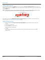
Adding Profile Data Files
You can add profile data files to the ORION folder on the computer at C:\Program Data\Badger Meter\ for viewing in the
ORION Endpoint Utility. Use the IMPORT button on the Profile Extraction screen to import files, or copy and paste files directly
into the ORION folder.
NNOTE: Profile data files must be .csv files, the format created when files are extracted/saved using Badger Meter software.
File names must have the same numerical format. An example of the format is shown here:
space
Date YYYYMMDD
space
30000191 20150126 190015
Endpoint serial number
Time HHMMSS
Once a file is saved, go to the ORION Endpoint Utility> Profile Extraction and select the file in the Select To View list to
display the graph. See "Viewing Profile Data" on page 41 for details.
Deleting Profile Data Files
1. On the computer, go to C:\Program Data\Badger Meter\ORION and open the folder with the saved profile
data files.
2. Select a file (or multiple files).
3. Press the Delete key on the keyboard.
Result: A confirmation window opens.
4. Click Yes.
Result: The files are deleted and will be removed from the Select To View list the next time you access the ORION
Endpoint Utility.
Page 44
ORI-UM-00019-EN-04
February 2015
Appendix
APPENDIX
February 2015
ORI-UM-00019-EN-04
Page 45
Glossary
GLOSSARY
ADE
The Absolute Digital Encoder is a position-based encoder that senses the position of each
number wheel to determine the reading for touch and AMR/AMI systems. The ADE encoder
displays as ”ENC“ on the software screens.
AMI
Advanced metering infrastructure (AMI).
AMR
An automated meter reading (AMR) system that uses radio frequency technology to transmit
meter readings between an endpoint and a data collection device.
C700D
Endpoint type exclusively used for connectivity with Elster/AMCo C700 digital encoders.
ELCD
Field display representing either an HR-E LCD encoder or High Resolution E-Series
Ultrasonic meter.
ENC
Used in the software to refer to a three-wire encoder, including the Absolute Digital Encoder.
endpoint
The term used to describe a transmitter which is an electronic device that produces radio waves.
HR-E
High resolution absolute encoder with eight-wheel mechanical display. The HR-E encoder
displays as “HRE” on the software screens.
HR-E LCD
High resolution (HR) electronic encoder with digital display and no moving parts. The HR-E LCD
encoder displays as “ELCD” on the software screens.
IR
Infrared light. Wireless transmission that requires a clear line of sight between the transmitter
and receiver. An IR programming cable connected to a collection device (laptop or handheld
computer) is used to read and program ORION endpoints.
lat/long
Abbreviation for latitude/longitude.
MM
Mobile message. An endpoint radio transmission heard by the laptop.
ORION CE
The ORION Classic (CE) endpoint is a one-way local automated meter reading (AMR) system
which communicates with a mobile receiver designed to read ORION Classic water and gas
endpoints. The receiver has Frequency Hopping Spread Spectrum (FHSS) technology to
minimize interference and eliminate FCC licensing.
ORION ME and
ORION SE
The ORION Migratable (ME) endpoint and ORION Fixed Network (SE) are two-way utility
management solutions. ORION Migratable and Fixed Network (in mobile mode) endpoints
communicate with a mobile transceiver designed to receive signals from and send signals to
ORION Migratable and Fixed Network water and gas endpoints. The transceiver has
Frequency Hopping Spread Spectrum (FHSS) technology to minimize interference and
eliminate FCC licensing.
raw reading
The numerical value from the encoder without reading resolution applied.
reading data
management software
Refers to Badger Meter reading data management software which acts as an interface between
the Utility's billing software and the meter reading devices.
RF
Radio frequency.
RSSI
Received Signal Strength Indicator.
RTR
The Recordall Transmitter Register (RTR) is used in conjunction with Recordall disc, turbo,
compound and fire series water meters to measure totalized flow through the meter and output
a signal to Badger Meter meter reading products.
transceiver
A device that has the ability to both transmit and receive.
Page 46
ORI-UM-00019-EN-04
February 2015
Removing Previous Software
REMOVING PREVIOUS SOFTWARE
Remove older software versions prior to installing a new version. Follow the instructions for your operating system.
NNOTE: If you are installing the ORION Endpoint Utility software for the first time (no previous versions installed), skip this
section and go to "Installing the Software" on page 49.
Removing Software – Windows 7
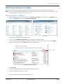
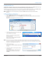
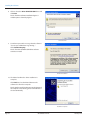
1. Click the Start button. Then click Control Panel > Programs and Features. If Control Panel is in Category view, as
shown, click Programs first, then click Programs and Features.
Control Panel
Category view
Result: The Programs and Features window opens.
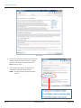
2. Locate and select ORION Endpoint Utility in the Programs and Features window.
To see the list of programs and features in alphabetic order, click the Change Your View icon and select Details.
When the view changes, click the Name column to sort alphabetically.
Change your view
Programs and Features detail view
3. Click Uninstall.
Result: The selected program uninstalls and any desktop icon is removed.
4. Close the Programs and Features window.
5. Restart the computer to complete the uninstall process.
February 2015
ORI-UM-00019-EN-04
Page 47
Removing Previous Software
Removing Software – Windows XP
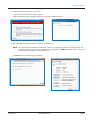
1. Click Start > Control Panel> Add or Remove Programs.
Control Panel
Result: The Add or Remove Programs window opens.
2. Locate and select ORION Endpoint Utility in the Add or Remove Programs window.
Add or Remove Programs window
3. Click Remove.
Result: The Uninstall window opens.
4. Follow the prompts and click Finish at the end.
Result: The selected program uninstalls and any desktop icon is removed.
5. Close the Add or Remove Programs window.
6. Restart the computer to complete the uninstall process.
Page 48
ORI-UM-00019-EN-04
February 2015
Installing the Software
INSTALLING THE SOFTWARE
The ORION Endpoint Utility software disc is provided by Badger Meter.
The basic software installation process is the same for Windows 7 and Windows XP. Windows 7 users must perform the
additional steps noted on page 52. Screen appearance depends on user personalization and operating system.
Remove older software prior to installing a new version. See "Removing Previous Software" on page 47.
NNOTE: In addition to the software installation instructions on the next four pages, instructions are included for "Installing
the ME Driver" on page 53 and "Configuring the USB Settings (Windows 7 and Windows XP)" on page 61. If you
previously installed the ORION Endpoint Utility software or have the ORION Mobile Reading System (ORS) software
installed, you can skip those sections.
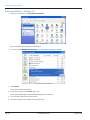
1. Load the ORION Endpoint Utility disc into the computer DVD drive.
NNOTE: A DVD drive is required to install the ORION Endpoint Utility software.
2. The disc folder may open automatically. If not, open Windows Explorer and browse to the disc drive location.
Result: The ORION Endpoint Utility files are displayed.
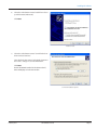
3. Double-click the setup.exe file.
Result: The ORION Endpoint Utility Setup Wizard opens.
February 2015
ORI-UM-00019-EN-04
Page 49
Installing the Software
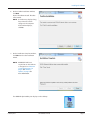
4. On the Welcome window,
click Next.
5. On the Select Installation Folder
window, do the following.
•
Verify where the software will be
located. The Program Files folder
is recommended. Click Browse to
change the location.
•
Verify that the radio button next to
Everyone is checked if more than
one person will be using
the software.
•
(Optional) Click Disc Cost... to
view available drives and space on
the computer before you install. A
window opens as shown in
the example. Click OK to close
the window.
•
Click Next.
Page 50
ORI-UM-00019-EN-04
February 2015
Installing the Software
6. On the Confirm Installation window,
click Next.
Result: The software installs. This takes
a few seconds.
NNOTE: A window may display asking
for permission to allow
changes to the computer.
If the window displays,
click Yes.
7. On the Installation Complete window,
click Close to close the installation
wizard.
NNOTE: MICROSOFT .NET 3.5 is
required to run the software
as designed. See "Minimum
System Requirements" on
page 5 and "Windows
Updates" on page 8 for
more information.
The ORION Endpoint Utility icon displays on the desktop.
February 2015
ORI-UM-00019-EN-04
Page 51
Installing the Software
Additional Steps - Windows 7 Users Only
For Windows 7 users, complete these steps to finish the software installation process.
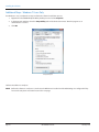
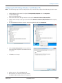
1. Right-click on the ORION Endpoint Utility desktop icon and select Properties.
2. In the Properties window, select the Compatibility tab and check the box next to "Run this program as an
administrator" as shown.
3. Click OK.
Compatibility tab
Software installation is complete.
NNOTE: Before the software is ready to use, make sure the ME Driver is installed and the USB Settings are configured if they
have not already been. Instructions start on the next page.
Page 52
ORI-UM-00019-EN-04
February 2015
Installing the Software
Installing the ME Driver
The ME Driver is required for communication between the ORION Endpoint Utility software and an ORION mobile transceiver.
Follow the driver installation instructions for your operating system if you need to install the driver.
The ME Driver only needs to be installed once. If you previously installed the ORION Endpoint Utility or other ORION software
such as the ORION Mobile Reading System, you already have the ME Driver and you may skip this section.
NNOTE: You will receive an error message when you connect the ORION mobile transceiver if you do not have the
ME Driver.
Installing the ME Driver with Windows 7
1. From the ORION Endpoint Utility software disc, copy the “OrionSE_USB_0_2.inf” file.
2. Click the Windows Start button. Then click Computer and paste the OrionSE_USB_0_2.inf file on the C:\ drive of
the laptop.
Result: The file should appear in the C:\ drive as shown here.
OrionSE_USB_0_2.inf file on the C:\ Drive
3. Connect the mobile transceiver to a power supply
and to a USB port on the laptop.
When it is connected to the laptop, turn the
transceiver power on.
Result: An error message is triggered and displays
briefly in the lower task bar.
Device Driver error message
NNOTE: If the error message does not display automatically, disconnect the transceiver and reconnect it. Make sure the
transceiver is connected to a power supply and is switched on after you connect it to the USB port. The power light
should be on, indicating the transceiver is on.
4. Click the error message.
Result: The Driver Software Installation window opens
as shown.
5. Click the link: "What can I do if my device did not
install properly?"
Result: Windows Help opens with instructions for
installing the driver software as shown on the
next page.
February 2015
ORI-UM-00019-EN-04
Driver Software Installation window
Page 53
Installing the Software
Windows Help
6. Scroll down in the Help window and click the link:
"Update a driver for hardware that isn't working
properly" at the bottom of the window in the
Note section as shown.
7. In the window that displays, click the link: "To
download and update a driver yourself."
NNOTE: An enlarged image of the Help section
is shown.
Update a driver
Page 54
ORI-UM-00019-EN-04
February 2015
Installing the Software
8. Click the link: "Open Device Manager." A portion of the Help screen with the link is shown.
Windows Driver Help
Result: Device Manager opens.
Device Manager
9. Locate and double-click the MSP430 based CDC Device.
Result: The Device Properties window opens.
February 2015
ORI-UM-00019-EN-04
Page 55
Installing the Software
10. Click to select the Driver tab.
On the Driver tab, click the Update Driver button.
Result: The Search window opens.
11. Select "Browse my computer for driver software."
Search
Device Properties
12. In the window that opens, type “C:\” in the field or
browse to select the C:\ drive.
NNOTE: It is not necessary to check the box
"Include subfolders."
13. Click Next.
Search C:\ Drive
Page 56
ORI-UM-00019-EN-04
February 2015
Installing the Software
14. A Windows Security window opens as shown.
Click the link: "Install this driver software anyway."
Result: The ME driver installs. A progress bar displays to show the installation progress.
Windows Security
Installation progress
15. When the ME driver software update is complete, a window opens.
NNOTE: The communication (COM) port number for the driver is now displayed at the top of the final window and
the Device Properties window. In the example shown, the ME driver is COM9. This COM number is important
to remember for setting up and using the software.
Click Close to close all remaining open windows.
ME Driver software updated
Device Properties with COM
February 2015
ORI-UM-00019-EN-04
Page 57
Installing the Software
Installing the ME Driver for Windows XP
NNOTE: This driver only needs to be installed once. If you already have the ME driver installed, skip this section.
1. From the software disc, copy the "OrionSE_USB_0_2.inf” file.
2. Click the Windows Start button. Then click My
Computer and paste the OrionSE_USB_0_2.inf file
on the C:\ drive of the laptop.
Result: The file appears in the C:\ drive as shown.
3. Connect the mobile transceiver to a power supply
and to a USB port on the laptop.
When it is connected to the laptop, turn the mobile
transceiver power on.
Result: A small window opens at the bottom of the
computer screen alerting you to new hardware.
Orion SE_USB_0_2.inf on the C:\ Drive
NNOTE: If the new hardware alert does not display automatically, disconnect the mobile transceiver and reconnect it.
Make sure the transceiver is connected to a power supply and is switched on after you connect it to the USB
port. The power light should be on, indicating the transceiver is on.
4. The New Hardware Wizard should open
automatically. If it does not, click the small new
hardware alert window described in Step 3.
5. Select the radio button next to "No, not this time"
and click Next.
New Hardware Wizard
Page 58
ORI-UM-00019-EN-04
February 2015
Installing the Software
6. Select the radio button next to "Install from a list or
specific location (Advanced)."
Click Next.
Install from a list
7. Select the radio button next to "Search for the best
driver in these locations."
Then check the box next to "Include this location in
the search:" and type “C:\” in the field below.
Click Next.
Result: The Wizard searches for the driver on the C:\
drive and displays it in the next window.
Search and installation options
February 2015
ORI-UM-00019-EN-04
Page 59
Installing the Software
8. Click to select the Orion SE Mobile COM driver and
click Next.
Result: The driver software installation begins. A
window opens to show the progress.
Select the driver
9. A window opens with a message that the software
"has not passed Windows Logo testing..."
Click Continue Anyway.
Result: The Orion SE Mobile COM driver software
continues to install.
Continue installation
10. The Wizard confirms the driver installation is
complete.
Click Finish to close the Wizard. Remove the
software disc from the computer.
Result: Another small window opens at the bottom of
the computer screen alerting you to new hardware. It
closes automatically.
Installation complete
Page 60
ORI-UM-00019-EN-04
February 2015
Installing the Software
Configuring the USB Settings (Windows 7 and Windows XP)
NNOTE: The USB settings only need to be configured once. If you have already configured the USB settings,skip this section.
1. Click the Windows Start button. Then right-click Computer/My Computer and select Properties.
2. Click Device Manager.
Result: Device Manager opens.
3. Scroll down in the Device Manager window and locate the Universal Serial Bus (USB) controllers.
4. Click the small arrow () or plus sign (+) to the left of the Universal Serial Bus (USB) controllers folder to display
the files.
5. For each USB Root Hub, click to select the device, then right-click and choose Properties.
Expanded USB Hub folder
USB Root Hub properties
6. Click the Power Management tab and uncheck the
box to "Allow the computer to turn off this device to
save power."
7. Click OK to save changes.
Power Management tab
8. Perform steps 5…7 for each USB Root Hub.
9. When finished, close the Device Manager window.
The ORION Endpoint Utility software is ready to use.
February 2015
ORI-UM-00019-EN-04
Page 61
INTENTIONAL BLANK PAGE
Page 62
ORI-UM-00019-EN-04
February 2015
INTENTIONAL BLANK PAGE
February 2015
ORI-UM-00019-EN-04
Page 63
ORION® Endpoint Utility
Making Water Visible®
ADE, HR-E, Making Water Visible, ORION, ReadCenter and RTR are registered trademarks of Badger Meter, Inc. Other trademarks appearing in this document are the property of their
respective entities. Due to continuous research, product improvements and enhancements, Badger Meter reserves the right to change product or system specifications without
notice, except to the extent an outstanding contractual obligation exists. © 2015 Badger Meter, Inc. All rights reserved.
www.badgermeter.com
The Americas | Badger Meter | 4545 West Brown Deer Rd | PO Box 245036 | Milwaukee, WI 53224-9536 | 800-876-3837 | 414-355-0400
México | Badger Meter de las Americas, S.A. de C.V. | Pedro Luis Ogazón N°32 | Esq. Angelina N°24 | Colonia Guadalupe Inn | CP 01050 | México, DF | México | +52-55-5662-0882
Europe, Middle East and Africa | Badger Meter Europa GmbH | Nurtinger Str 76 | 72639 Neuffen | Germany | +49-7025-9208-0
Europe, Middle East Branch Office | Badger Meter Europe | PO Box 341442 | Dubai Silicon Oasis, Head Quarter Building, Wing C, Office #C209 | Dubai / UAE | +971-4-371 2503
Czech Republic | Badger Meter Czech Republic s.r.o. | Maříkova 2082/26 | 621 00 Brno, Czech Republic | +420-5-41420411
Slovakia | Badger Meter Slovakia s.r.o. | Racianska 109/B | 831 02 Bratislava, Slovakia | +421-2-44 63 83 01
Asia Pacific | Badger Meter | 80 Marine Parade Rd | 21-06 Parkway Parade | Singapore 449269 | +65-63464836
China | Badger Meter | 7-1202 | 99 Hangzhong Road | Minhang District | Shanghai | China 201101 | +86-21-5763 5412