1
pcMAINFRAME and Across the Boards
Communications Device Drivers
cfSOFTWARE Confidential
2000
Across the Boards Release 3.35
Copyright 2000, cfSOFTWARE
Revised February 2000
All rights reserved
cfSOFTWARE
2454 E. Dempster
Suite 201
Des Plaines, IL 60016
847/824-7180
www.cfsoftware.com
Across the Boards
Communications Device Drivers
Table of Contents
Page i
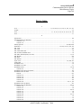
Table of Contents
Introduction .........................................................................................................................1
Section 1 - Device Driver List.............................................................................................3
1.1
pcMAINFRAME 3.x Device Codes.........................................................................................................7
Section 2 - Across the Boards Memory Sizes ..................................................................9
Across the Boards Memory Overhead (as of 6/24/93) ...........................................................................................9
Section 3 - General Information.......................................................................................11
General Device Support........................................................................................................................................11
Configuration Program - MAINCON ...................................................................................................................11
Keyboard Layout for Manual Mode 3270 Emulation...........................................................................................11
3270 Controllers ...................................................................................................................................................11
Flicker...................................................................................................................................................................13
Field Attributes.....................................................................................................................................................13
CICS Terminal Definition ....................................................................................................................................14
Section 4 - Device Driver Configuration and Usage.......................................................15
4.0
4.1
4.2
4.3
4.4
4.5
4.6
4.7
4.8
4.9
4.10
4.11
4.12
CFXASNC.BIN - Async (pcMAINFRAME Version 1.x-3.x only)...................................................15
CFXIRMA.BIN, CFXIRMA.DLL, CFXIRMA3.DLL
- Irma, Irma2, Irma3, and Irma Compatibles ..........................................................16
CFXPCOX.BIN, CFXPCOX.WBN
- PCOX/CXI (3278/9, DFT, Remote, and LAN)
- Novell SNA Gateway ...........................................................................................19
CFXPC3X.BIN
- IBM 3270PC/AT and 3270-Workstation .............................................................21
CFXFORT.BIN - Forte 3278/9 Card/Irma2 3278/9 Card .................................................................22
CFXIDEX.BIN, CFXIDEX.WBN - IDEAcomm 3278/9 Card ............................................................23
CFXITTX.BIN, CFXITTX.WBN - ITT 3278/9 Cards .......................................................................24
CFXIBMX.BIN, CFXIBMX.DLL, CFXIBMX3.DLL
- IBM 3278/9 Card in CUT Mode ..........................................................................25
CFXASTX.BIN, CFXASTX.WBN
- AST Remote 3274 Emulator Card........................................................................27
CFXPROX.BIN, HYDPROX.BIN, CFXPROX.DLL
- Protocol Converter IBM 3101 (Byte Mode - Model 1)
- Protocol Converter IBM 3101 (Specifc to Hydra) ...............................................28
CFXMPLS.BIN, CFXMPLS.WBN - MicroPlus 3278/9 Card...............................................................30
CFXPATH.BIN, CFXPATH.WBN - Pathway BISYNC 2.2E
CFXPAT4.BIN, CFXPAT4.WBN - Pathway Remote for Pathway SNA Release (3.00 & Above)
OLDPATH.BIN, OLDPATH.WBN - Version of CFXPATH Using Old Style Calls
OLDPAT4.BIN, OLDPAT4.WBN - Version of CFXPAT4 Using Old Style Calls..............................31
CFXSPEC.BIN, CFXSPEC.DLL - Special/Customized Device Drivers ...........................................33
cfSOFTWARE Confidential, 2000
Across the Boards
Communications Device Drivers
Table of Contents
Page ii
4.13
4.14
4.15
4.16
4.17
4.19
4.20
4.21
4.22
4.23
4.24
4.25
4.25a
4.25b
4.25c
4.25d
4.25e
4.25f
4.26
4.27
4.28
4.29
4.30
4.31
4.32
4.33
4.34
4.35
4.36
CFXLV3X.BIN, CFXLV3X.WBN - IBM Level 3 PC-3270 Emulation
- * PSAPI * CFXLV3X.302
- IBM Level 3 PC-3270 Emulation With Fix for 3.02 Bug.....................................34
CFXHLLX.BIN, CFXHLLX.WBN - DOS HLLAPI-based Emulators ..............................................38
CFX525X.BIN, CFX525X.WBN
- IBM Twinax 5250 Emulation
- * XAPI/DIALOG Only *, CFX5253.BIN, CFX5253.WBN
- Special IBM Twinax 5250 Emulation ..................................................................48
CFXDECX.BIN, CFXDECX.DLL - Protocol Converter VT100/ANSI Mode .....................................50
CFXPC2X.BIN
- PC-to-PC RS232
- * APPX, XAPI and DIALOG Only * ...................................................................51
CFX525A.BIN, CFX525A.WBN
- AST Twinax Emulator
- * XAPI, and DIALOG Only * ..............................................................................52
CFXVINX.BIN, CFXVINX.WBN - Banyan VINES Gateway.............................................................53
CFXTTYX.BIN - Async TTY
- * APPX, XAPI and DIALOG Only * ...................................................................54
CFXTYMX.BIN, CFXTYMX.DLL - Tymnet78 Protocol Converter...................................................55
cfDFT - Resident DFT Facility by cfSOFTWARE
CFXDFTX.BIN - Stub Driver To Access The Resident cfDFT Modules
DFT.COM
- Terminate-And-Stay-Resident Facility for cfDFT
CFXDFTN.BIN - Non-SNA (Loaded And Made Resident by DFT.COM)
CFXDFTS.BIN
- SNA (Loaded And Made Resident by DFT.COM)
CFXDFTX.WBN - Windows Version of CFXDFTX.BIN OS/2 Modules:
CFXDFTX.DLL, CFXDFTY.DLL, DFT.EXE, PMDFT.EXE, CFXDFTN.DLL, CFXDFTS.DLL ....56
CFX400X.BIN, CFX400X.DLL
- IBM PC Support AS/400
- 5250 Emulation.....................................................................................................59
CFXEXTW.DLL - Attachmate Extra! for Windows **Version 3.00** ..............................................61
CFXEXTW.DLL - Attachmate Extra! for Windows **Version 3.10** ..............................................62
CFXEXTW.DLL - Attachmate Extra! for Windows **Version 3.20** ..............................................63
CFXEXTW.DLL - Attachmate Extra! for Windows **Version 3.35** **Version 3.40** ...............64
CFXEXTW.DLL - Attachmate Extra! for Windows **Version 4.00** **Version 4.01**
**Version 4.10** **Version 4.20**......................................................................65
CFXEXTW.DLL, CFXEXTW3.DLL - Attachmate Extra! Personal Client ..........................................66
CFXEXTW.DLL - NetWare 3270 LAN Professional for Windows *Version 2.10*
(Driver is Also Used for Data Interfaces DI3270 Product).....................................67
CFXIRMW.DLL - Irma Workstation for Windows ............................................................................68
CFXCMGX.DLL - OS/2 EE Communications Manager .....................................................................69
cfDFT/Non-SF
- Resident DFT Facility by cfSOFTWARE ............................................................70
CFXRUMB.DLL - Rumba (Windows HLLAPI-based Product) .........................................................71
CFXEICO.DLL - Eicon Access (Windows HLLAPI-based Product) ...............................................74
CFXIBMW.DLL - IBM Personal Communications for Windows (2.00 & Above) ............................75
CFXXIRC.BIN, CFXXIRC.DLL - Xircom Pocket 3270 Adapter......................................................78
CFX220X.DLL, CFX220X3.DLL - VT220 Emulation........................................................................79
CFXDYNC.DLL - Dynacomm Elite for Windows..............................................................................80
CFXLWPW.DLL - Telnet TN3270 without Structured Fields
- Novell LAN Workplace for DOS (Windows Support).........................................82
CFXLWPW.DLL - Telnet TN3270 with Structured Fields
- Novell LAN Workplace for DOS (Windows Support).........................................82
cfSOFTWARE Confidential, 2000
Across the Boards
Communications Device Drivers
Table of Contents
Page iii
4.37
CFXNFSW.DLL
4.38
CFXNFSW.DLL
4.39
CFXT3NW.DLL
4.40
CFXT3NW.DLL
4.41
CFXT3WS.DLL
4.42
CFXT3WS.DLL
4.43
CFXT3FT.DLL
4.44
CFXT3FT.DLL
4.45
CFXT2LW.DLL
4.46
CFXT2NF.DLL
4.47
CFXT2NW.DLL
4.48
CFXT2WS.DLL
4.49
CFXT2FT.DLL
4.50
4.51
4.52
4.53
4.55
CFXNVLW.DLL
CFXDN22.DLL
CFXWHLL.DLL
CFXOMNW.DLL
CFXIBWS.DLL
4.56
CFX62DE.DLL
4.59
CFXT3WS3.DLL
4.60
CFXT3WS3.DLL
4.61
CFXCMGS.DLL
4.62
4.65
CFXEXTO.DLL
CFXT3IO.DLL
4.66
CFXT3IO.DLL
4.67
CFXT3FO.DLL
4.68
CFXT3FO.DLL
4.69
CFXT3LO.DLL
- Telnet TN3270 without Structured Fields
- Sun PC/NFS (Windows Support) .........................................................................83
- Telnet TN3270 with Structured Fields
- Sun PC/NFS (Windows Support) .........................................................................83
- Telnet TN3270 without Structured Fields
- Netmanage Newt/Chameleon ...............................................................................84
- Telnet TN3270 with Structured Fields
- Netmanage Newt/Chameleon ...............................................................................84
- Telnet TN3270 without Structured Fields
- Windows Sockets .................................................................................................85
- Telnet TN3270 with Structured Fields
- Windows Sockets .................................................................................................85
- Telnet TN3270 without Structured Fields
- FTP PC/TCP (Windows Support) ........................................................................86
- Telnet TN3270 with Structured Fields
- FTP PC/TCP (Windows Support) ........................................................................86
- Telnet VT220
- Novell LAN Workplace for DOS (Windows Support).........................................87
- Telnet VT220
- Sun PC/NFS (Windows Support) .........................................................................88
- Telnet VT220
- Netmanage Newt/Chameleon ...............................................................................89
- Telnet VT220
- Windows Sockets .................................................................................................90
- Telnet VT220
- FTP PC/TCP (Windows Support) ........................................................................91
- Netware LAN Workstation for Windows .............................................................92
- DECNET/Pathworks VT220 ................................................................................93
- Windows Open HLLAPI (WOSA) - 16 bit ..........................................................95
- ICOT Omnipath for Windows ..............................................................................96
- Personal Communications for Windows
- SF Support............................................................................................................97
- Dynacomm/Elite
- APPC Driver.........................................................................................................98
- Telnet TN3270 without Structured Fields
- Windows Sockets for Win32 ................................................................................99
- Telnet TN3270 with Structured Fields
- Windows Sockets for Win32 ................................................................................99
- OS/2 Communications Manager
- SF Support..........................................................................................................100
- Extra! for OS/2 ...................................................................................................101
- Telnet TN3270 without Structured Fields
- IBM TCP/IP for OS/2.........................................................................................102
- Telnet TN3270 with Structured Fields
- IBM TCP/IP for OS/2.........................................................................................102
- Telnet TN3270 without Structured Fields
- FTP PC/TCP for OS/2........................................................................................103
- Telnet TN3270 with Structured Fields
- FTP PC/TCP for OS/2........................................................................................103
- Telnet TN3270 without Structured Fields
- Novell LAN Workplace for OS/2.......................................................................104
cfSOFTWARE Confidential, 2000
Across the Boards
Communications Device Drivers
Table of Contents
Page iv
4.70
4.75
4.76
4.79
4.80
4.81
4.82
4.83
4.84
4.85
4.86
4.87
4.88
4.89
4.90
4.91
4.92
4.93
4.94
4.95
4.96
4.102
4.103
4.104
4.105
4.106
4.107
4.109
4.110
4.111
4.112
4.113
CFXT3LO.DLL
- Telnet TN3270 with Structured Fields
- Novell LAN Workplace for OS/2 .......................................................................104
CFXWHLL3.DLL - Windows Open HLLAPI (WOSA) - 32 bit.........................................................105
CFXRUMO.DLL - Rumba for OS/2..................................................................................................106
CFX5253.BIN
- Special 5250 for S/36 & ES/3270.......................................................................107
CFX147W.DLL - Memorex Telex 1472 for Windows....................................................................109
CFXIRMA3.DLL via CFXNTGT.DLL
- WOW Irma/Irma2/Irma3 ....................................................................................110
CFXFORT3.DLL via CFXNTGT.DLL
- WOW Forte ........................................................................................................111
CFXIBMX3.DLL via CFXNTGT.DLL
- WOW IBM 3278/9 CUT ....................................................................................112
CFXWHL5.DLL - WOSA HLLAPI 5250 ........................................................................................113
CFXRUMB3.DLL - Rumba for the Mainframe for Windows NT.......................................................114
CFXCMG5.DLL - OS/2 Communications Manager 5250 ................................................................116
CFXT2IO.DLL
- Telnet VT220
- IBM TCP/IP for OS/2.........................................................................................117
CFXT2FO.DLL - Telnet VT220
- FTP PC/TCP for OS/2 ........................................................................................118
CFXT2LO.DLL - Telnet VT220
- Novell LAN Workplace for OS/2 .......................................................................119
CFXNULL.DLL - Null Driver..........................................................................................................120
CFXRUM5.DLL - Rumba for Windows 5250 ..................................................................................121
CFXIRM5.DLL - Irma for Windows 5250......................................................................................122
CFXT2WS3.DLL - Telnet VT220
- Windows Sockets for Win32 ..............................................................................123
CFX220X3.DLL via CFXNTGT.DLL
- WOW VT220 Async ..........................................................................................124
CFXEXTW3.DLL - Win32 Extra! for NT/95 .....................................................................................125
CFX62RU.DLL - Rumba for Windows LU6.2................................................................................128
CFX320X.DLL
- VT320 Emulation ...............................................................................................129
CFXT4LW.DLL - Telnet VT320
- Novell LAN Workplace for DOS (Windows Support).......................................130
CFXT4NF.DLL - Telnet VT320
- Sun PC/NFS (Windows Support) .......................................................................131
CFXT4NW.DLL - Telnet VT320
- Netmanage Newt/Chameleon..............................................................................132
CFXT4WS.DLL - Telnet VT320
- Windows Sockets................................................................................................133
CFXT4FT.DLL
- Telnet VT320
- FTP PC/TCP (Windows Support) ......................................................................134
CFXT4IO.DLL
- Telnet VT320
- IBM TCP/IP for OS/2.........................................................................................135
CFXT4FO.DLL - Telnet VT320
- FTP PC/TCP for OS/2 ........................................................................................136
CFXT4LO.DLL - Telnet VT320
- Novell LAN Workplace for OS/2 .......................................................................137
CFXT4WS3.DLL - Telnet VT320
- Windows Sockets for Win32 ..............................................................................138
CFX320X3.DLL via CFXNTGT.DLL
- WOW VT320 Async ..........................................................................................139
cfSOFTWARE Confidential, 2000
Across the Boards
Communications Device Drivers
Table of Contents
Page v
4.114
4.115
4.116
4.117
4.118
4.122
4.123
4.124
4.125
4.126
4.127
4.129
4.130
4.131
4.132
4.133
4.134
4.135
4.136
4.137
4.138
4.139
4.140
4.141
4.143
4.144
4.145
4.146
4.147
4.148
4.149
CFXATLW.DLL - APPX/TCP
- Novell LAN Workplace for DOS (Windows Support).......................................140
CFXATNF.DLL - APPX/TCP
- Sun PC/NFS (Windows Support) .......................................................................141
CFXATNW.DLL - APPX/TCP
- Netmanage Newt/Chameleon .............................................................................142
CFXATWS.DLL - APPX/TCP
- Windows Sockets ...............................................................................................143
CFXATFT.DLL - APPX/TCP
- FTP PC/TCP (Windows Support) ......................................................................144
CFXATWS3.DLL - APPX/TCP
- Win32 Sockets....................................................................................................145
CFXNSEL3.DLL - NS/Elite Plus for Win32 .....................................................................................146
CFXWRQI3.DLL - WRQ Reflection for IBM Win32 .......................................................................147
CFXSWFT3.DLL - NetManage Swift for Win32...............................................................................148
CFXIBMW3.DLL - Personal Communications for Win95/NT ..........................................................149
CFXIBWS3.DLL - Personal Communications for Win95/NT - SF...................................................150
CFXRASW.DLL - Remote Access Service Control Driver for Win16.............................................151
CFX62WC3.DLL (ATB/Win32)
- WinCPIC LU6.2 Win32 .....................................................................................154
CFXATPP.DLL (ATB/Win16)
- APPX/TCP
- cfPPP (Embedded TCP/IP and PPP Stack) ........................................................156
CFXATPPD.DLL (ATB/DOS) - APPX/TCP - cfPPP (Embedded TCP/IP and PPP Stack) .............157
CFX62NS3.DLL - IBM Personal Communications LU6.2 for Win95/NT.......................................158
CFX62EP3.DLL - Extra! LU6.2 Win32 ...........................................................................................160
CFX62RU3.DLL - Rumba LU6.2 Win32 .........................................................................................161
CFXATPP3.DLL (ATB/Win32)
- APPX/TCP
- cfPPP (Embedded TCP/IP and PPP Stack) ........................................................163
CFX62SS3.DLL (ATB/Win32)
- SNA Server APPC LU6.2 Win32.......................................................................164
CFX62IB3.DLL - IBM Personal Communications APPC (LU6.2) for Win95/NT .........................165
CFXT7WS3.DLL - Telnet TN3270 with TN3287 (without Structured Fields)
- Windows Sockets for Win32 ..............................................................................166
CFXT7WS3.DLL - Telnet TN3270 with TN3287 (with Structured Fields)
- Windows Sockets for Win32 ..............................................................................167
CFXT5WS3.DLL - Telnet TN5250
- Windows Sockets for Win32 ..............................................................................168
CFXIBM53.DLL - IBM Personal Communications for Win32 -5250 ..............................................169
CFXCA403.DLL - Client Access/400 5250 (Win32) .......................................................................170
CFXRUM53.DLL - Rumba for Win32 - 5250....................................................................................171
CFXPSPW3.DLL - Zephyr Passport for Win32.................................................................................172
CFXWSRF3.DLL - ICOM WinSurf+ for Win32 (3270)....................................................................173
CFXBLUE3.DLL - NewHart Systems Blues (Win32) .......................................................................174
CFXCFMP3.DLL - cfMEMPIPE Driver For APPX/TPNS Service ..................................................175
Section 5 - General Configuration and Usage Information .........................................177
5.1
5.2
5.3
Protocol Converter 3101 and VT100 - Special Considerations ...........................................................177
Configuring the Telnet TN3270 Drivers ..............................................................................................181
Configuring the Telnet VT220 Drivers ................................................................................................184
cfSOFTWARE Confidential, 2000
Across the Boards
Communications Device Drivers
Table of Contents
Page vi
5.4
5.5
5.6
5.7
5.8
5.9
5.10
5.11
5.12
5.13
5.14
5.15
5.16
5.17
TCP/IP Host Names and Addresses .....................................................................................................185
Multiple COMM Port and Modem Server Support in Across the Boards/DOS...................................186
VTAM/NCP Issues for Across the Boards...........................................................................................188
Windows NT CFXNTDD.SYS Installation..........................................................................................189
ATB/Win16 Applications under WOW (Windows-on-Windows)
in Windows NT and in Windows 95 ....................................................................................................190
Identifying HLLAPIs............................................................................................................................192
Configuring the APPX/TCP Drivers ....................................................................................................194
Configuring the Telnet VT320 Drivers ................................................................................................196
DOS HLLAPI Passthroughs .................................................................................................................197
CFXVXDT/CFXVXDS Usage
- ATB/Win16 Driver Access for ATB/DOS .........................................................198
cfPPP Driver Usage..............................................................................................................................200
CFXSWTC
- ATB/DOS Extended DOS Driver Support .........................................................203
LU6.2 Configuration ............................................................................................................................204
Configuring the Telnet TN5250 Drivers ..............................................................................................213
Section 6 - MAINCON Driver Configuration.................................................................. 215
Device Configuration..........................................................................................................................................215
MAINCON Quick Notes ....................................................................................................................................215
Running MAINCON...........................................................................................................................................216
6.1
MAINCON Panel A1 VDT/Keyboard Config ....................................................................................217
6.2
MAINCON Panel A2 APPX and Troubleshooting .............................................................................222
6.3
MAINCON Panel B1 CUT Mode/Single Session 3270 IBM 3270 Connection ................................226
6.4
MAINCON Panel B2 CUT Mode/Single Session DCA Irma Coax Card ..........................................227
6.5
MAINCON Panel B3 Forte .................................................................................................................228
6.6
MAINCON Panel B4 IDEAcomm ......................................................................................................229
6.7
MAINCON Panel B5 AST Remote.....................................................................................................230
6.8
MAINCON Panel B6 Pathway Remote...............................................................................................231
6.9
MAINCON Panel B7 CUT Mode/Single Session 3270 Xircom Pocket ............................................232
6.10
MAINCON Panel C1 Multi-host Session HLLAPI/API/Workstation/etc..........................................233
6.11
MAINCON Panel C2 cfDFT Coax .....................................................................................................236
6.12
MAINCON Panel C3 PCOX/CXI/Novell ...........................................................................................238
6.13
MAINCON Panel C4 Banyan VINES.................................................................................................239
6.14
MAINCON Panel D1 COMM Port Assignment .................................................................................240
6.15
MAINCON Panel D2 IBM 3101.........................................................................................................243
6.16
MAINCON Panel D3 DEC VT100 .....................................................................................................249
6.17
MAINCON Panel D4 Tymnet78 .........................................................................................................255
6.18
MAINCON Panel D5 TTY and PC-to-PC (RS232)............................................................................261
6.19
MAINCON Panel D6 DEC VT220 .....................................................................................................263
6.20
MAINCON Panel D7 DEC VT320 .....................................................................................................274
6.21
MAINCON Panel E1 Single Session TN3270 ....................................................................................286
6.22
MAINCON Panel E2 Telnet VT220 ...................................................................................................289
6.23
MAINCON Panel E3 DECNET VT220..............................................................................................300
6.24
MAINCON Panel E4 Telnet VT320 ...................................................................................................311
6.25
MAINCON Panel E5 APPX/TCP .......................................................................................................322
6.26
MAINCON Panel E6 APPX/TCP - cfPPP ..........................................................................................325
6.27
MAINCON Panel E7 TN3270 with TN3287 Support ........................................................................328
6.28
MAINCON Panel E8 Single Session TN5250 ....................................................................................332
6.29
MAINCON Panel F1 PC Support AS/400 ..........................................................................................334
6.30
MAINCON Panel F2 5250, IBM and AST .........................................................................................335
cfSOFTWARE Confidential, 2000
Across the Boards
Communications Device Drivers
Table of Contents
Page vii
6.31
6.32
6.33
6.34
6.35
6.36
6.37
6.38
6.39
MAINCON Panel F3 5250 HLLAPI...................................................................................................336
MAINCON Panel G1 Dynacomm Elite LU6.2 ...................................................................................338
MAINCON Panel G2 WinCPIC LU6.2 ..............................................................................................341
MAINCON Panel G3 Personal Comm LU6.2 NT/95 .........................................................................344
MAINCON Panel G4 Extra! LU6.2 NT/95 ........................................................................................347
MAINCON Panel G5 Rumba LU6.2 NT/95 .......................................................................................350
MAINCON Panel G6 WinAPPC LU6.2 .............................................................................................353
MAINCON Panel G7 Personal Comm LU6.2 NT/95 APPC ..............................................................356
MAINCON Panel X1 CFMPIPE Driver ..............................................................................................359
Section 7 - Miscellaneous Topics..................................................................................361
7.1
7.2
7.3
7.4
7.5
Rational Systems DOS Extender ..........................................................................................................361
WATCOM C........................................................................................................................................362
Language Translation Considerations ..................................................................................................363
Year 2000 Date Handling in Across the Boards...................................................................................364
MAINCON ASCII Characters .............................................................................................................365
Device Index ....................................................................................................................369
cfSOFTWARE Confidential, 2000
Across the Boards
Communications Device Drivers
Table of Contents
Page viii
cfSOFTWARE Confidential, 2000
Across the Boards
Communications Device Drivers
Introduction
Page 1
Introduction
This manual describes the configuration and usage of the many communications devices supported by Across
the Boards and pcMAINFRAME. This manual consists of eight major sections:
1.
2.
3.
4.
5.
6.
7.
8.
Device Driver List
Across the Boards Memory Sizes
General Information
Device Driver Configuration and Usage
General Configuration and Usage Information
MAINCON Device Configuration
Miscellaneous Topics
Device Index
General information of various sorts is included in Sections 1, 2, 3 and 7.
When configuring a device driver for use with a specific device, information from Sections 4, 5 and 6 may be of
use, as well as the Device Index.
If you are unsure of which device driver to use, use the Device Index or the Device Driver List to find the
correct device driver. Once the device driver has been determined, specific configuration and usage notes will
be found in Section 4, Device Driver Configuration and Usage. At the beginning of each driver subsection is a
reference to the MAINCON configuration panel used to configure that driver. A description of that MAINCON
configuration panel can be found in Section 6, MAINCON Device Configuration.
cfSOFTWARE Confidential, 2000
Across the Boards
Communications Device Drivers
Introduction
Page 2
cfSOFTWARE Confidential, 2000
Across the Boards
Communications Device Drivers
Section 1 - Device Driver List
Page 3
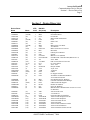
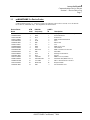
Section 1 - Device Driver List
Device Driver
Name
Notes
ATB
dvc#
DIALOG
dev(name)
CFXASNC
CFXIRMA
CFXPCOX
CFXPC3X
CFXFORT
CFXIDEX
CFXITTX
CFXIBMX
CFXASTX
CFXPROX
CFXMPLS
CFXPATH
CFXSPEC
CFXLV3X
CFXHLLX
CFX525X
CFXDECX
CFX232X
CFX525A
CFXVINX
CFXTTYX
CFXTYMX
CFXDFTX
CFX400X
CFXEXTW
(1-Y)
(1345-H)
(12)
(1)
(1345-H)
(12)
(12)
(1345-H)
(12)
(134J)
(12)
(12)
(Y)
(12)
(12)
(12)
(134)
(13-Y)
(12)
(12)
(1)
(134)
(124-S)
(12)
(3)
0
1
2
3
4
5
6
7
8
9
10
11
12
13
14
15
16
17
19
20
21
22
23
24
25
--IRM
PCO
327
FOR
IDE
ITT
IBM
AST
PRO/3101
MIC
PAT
SPE
LEV/API
ENT/HLLAPI
525
VT1/DEC
PC2
52A
BAN/VIN
TTY
TYM
DFT
AS4
EXT
CFXIRMW
CFXCMGX
CFXDFTX
CFXRUMB
CFXEICO
CFXIBMW
(3)
(4)
(124-S)
(3)
(3)
(3)
26
27
28
29
30
31
IRW
CMG
DFT
RUM
EIC
IBW
CFXXIRC
CFX220X
CFXDYNC
CFXLWPW
CFXLWPW
CFXNFSW
CFXNFSW
CFXT3NW
CFXT3NW
CFXT3WS
(13)
(345-H)
(3)
(3-S)
(3-S)
(3-S)
(3-S)
(3-S)
(3-S)
(3-S)
32
33
34
35
36
37
38
39
40
41
XIR
VT2
DYN
TN3LWPW
TN3LWPW
TN3NFSW
TN3NFSW
TN3NEWT
TN3NEWT
TN3WSOK
Description
Async (pcMAINFRAME Version 1.x-3.x only)
Irma/Irma2/Irma3
PCOX/CXI
IBM 3270PC/Workstation
Forte
IDEA Card
ITT
IBM 3278/9 CUT Mode
AST Remote
IBM 3101 Protocol Converter
MicroPlus
Pathway/ICOT Remote
Special
IBM Level 3.0 (PSAPI)
ENT/HLLAPI DOS HLLAPI (IBM Level 1.0)
5250 - IBM
DEC VT100 Protocol Converter
PC to PC RS232
5250 - AST
Banyan VINES
Async TTY
Tymnet78
cfDFT
PC Support AS/400
Attachmate for Windows/NetWare
3270 LAN Professional
Irma Workstation for Windows
OS/2 EE Communications Manager
cfDFT without SF Support
Rumba for Windows
Eicon for Windows
IBM Personal Communications Version 2.x/3.x/4.x
for Windows
Xircom Pocket 3270
VT 220 Driver
Dynacomm Elite for Windows
TN3270 LAN Workplace non-SF
TN3270 LAN Workplace
TN3270 PC/NFS non-SF
TN3270 PC/NFS
TN3270 Newt/Chameleon non-SF
TN3270 Newt/Chameleon
TN3270 Windows Sockets non-SF
cfSOFTWARE Confidential, 2000
Across the Boards
Communications Device Drivers
Section 1 - Device Driver List
Page 4
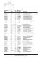
Device Driver
Name
Notes
CFXT3WS
CFXT3FT
CFXT3FT
CFXT2LW
CFXT2NF
CFXT2NW
CFXT2WS
CFXT2FT
CFXNVLW
CFXDN22
CFXWHLL
CFXOMNW
CFXIBWS
(3-S)
(3-S)
(3-S)
(3)
(3)
(3)
(3)
(3)
(3)
(3)
(3)
(3)
(3)
CFX62DE
CFXT3WS3
CFXT3WS3
CFXCMGS
CFXEXTO
CFXT3IO
CFXT3IO
CFXT3FO
CFXT3FO
CFXT3LO
CFXT3LO
CFXWHLL3
CFXRUMO
CFX5253
CFX147W
CFXIRMA3
CFXFORT3
CFXIBMX3
CFXWHL5
CFXRUMB3
CFXCMG5
CFXT2IO
CFXT2FO
CFXT2LO
CFXNULL
CFXRUM5
CFXIRM5
CFXT2WS3
CFX220X3
CFXEXTW3
CFX320X
CFXT4LW
CFXT4NF
(3)
(5-S)
(5-S)
(4)
(4)
(4-S)
(4-S)
(4-S)
(4-S)
(4-S)
(4-S)
(5)
(4)
(1)
(3)
(W)
(W)
(W)
(3)
(5)
(4)
(4)
(4)
(4)
(345)
(3)
(3)
(5)
(W)
(5)
(345-H)
(3)
(3)
ATB
dvc#
DIALOG
dev(name)
42
43
44
45
46
47
48
49
50
51
52
53
55
TN3WSOK
TN3FTP
TN3FTP
TN2LWPW
TN2NFSW
TN2NEWT
TN2WSOK
TN2FTP
NVLW
DN220
WHLL
OMNIW
IBW-SF
56
59
60
61
62
65
66
67
68
69
70
75
76
79
80
81
82
83
84
85
86
87
88
89
90
91
92
93
94
95
102
103
104
--TN3WSOK3
TN3WSOK3
CMG-SF
EXO
TN3IBMO
TN3IBMO
TN3FTPO
TN3FTPO
TN3LWPO
TN3LWPO
WHLL3
RMO
525-ES3270
MT1472W
NT-Irma
NT-FORTE
NT-IBM
WHLL-5250
NT-Rumba
CMG-5250
TN2IBMO
TN2FTPO
TN2LWPO
NULL
Rumba-5250
Irma-5250
TN2WSOK3
NT-VT220
NT-Extra
VT320
TN4LWPW
TN4NFSW
Description
TN3270 Windows Sockets
TN3270 FTP PC/TCP non-SF
TN3270 FTP PC/TCP
Telnet VT220 LAN Workplace
Telnet VT220 PC/NFS
Telnet VT220 Newt/Chameleon
Telnet VT220 Windows Sockets
Telnet VT220 FTP PC/TCP
Novell LAN Workstation/Win
DECNET/Pathworks VT220
Windows WOSA HLLAPI
ICOT Omnipath for Windows
Personal Communications for Windows,
with SF support
Dynacomm Elite LU6.2
TN3270 Win32 Sockets non-SF
TN3270 Win32 Sockets
OS/2 EE Comm Mgr/SF
Extra! for OS/2 (not SF!)
TN3270 IBM TCP/IP/OS2 non-SF
TN3270 IBM TCP/IP/OS2
TN3270 FTP PC/TCP/OS2 non-SF
TN3270 FTP/PC/TCP/OS2
TN3270 Novell LWP/OS2 non-SF
TN3270 Novell LWP/OS2
Win32 WOSA HLLAPI
Rumba for OS/2 (not SF!)
Special 5250 for S/36 & ES/3270
Memorex Telex 1472 for Windows
WOW Irma/Irma2/Irma3
WOW Forte
WOW IBM 3278/9 CUT Mode
Windows WOSA HLLAPI 5250
Win32 Rumba for NT
OS/2 Comm Mgr 5250
Telnet VT220 IBM TCP/IP/OS2
Telnet VT220 FTP/PC/TCP/OS2
Telnet VT220 Novell LWP/OS2
Null Device
Rumba/Win16 HLLAPI 5250
Irma/Win16 HLLAPI 5250
Telnet VT220 Win32 Sockets
WOW VT220 Async
Win32 Extra! for NT/95
VT 320 Driver
Telnet VT320 LAN Workplace
Telnet VT320 PC/NFS
cfSOFTWARE Confidential, 2000
Across the Boards
Communications Device Drivers
Section 1 - Device Driver List
Page 5
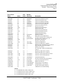
Device Driver
Name
Notes
ATB
dvc#
DIALOG
dev(name)
CFXT4NW
CFXT4WS
CFXT4FT
CFXT4IO
CFXT4FO
CFXT4LO
CFXT4WS3
CFX320X3
CFXATLW
CFXATNF
CFXATNW
CFXATWS
CFXATFT
CFXATWS3
CFXNSEL3
CFXWRQI3
CFXIBMW3
CFXIBWS3
CFXRASW
CFX62WC3
CFXATPP
CFXATPPD
CFX62NS3
CFX62EP3
CFX62RU3
CFXATPP3
(3)
(3)
(3)
(4)
(4)
(4)
(5)
(W)
(3-D)
(3)
(3)
(3-D)
(3)
(5)
(5)
(5)
(5)
(5)
(3-D)
(5)
(3-D)
(6)
(5)
(5)
(5)
(5)
105
106
107
109
110
111
112
113
114
115
116
117
118
122
123
124
126
127
129
130
131
132
133
134
135
136
TN4NEWT
TN4WSOK
TN4FTP
TN4IBMO
TN4FTPO
TN4LWPO
TN4WSOK3
NT-VT320
------------NS-ELITE3
WRQI3
NT-PCOM
NT-PCOM-SF
----ATCP-PPP
ATCP-PPPD
---------
CFX62SS3
CFX62IB3
CFXT7WS3
CFXT7WS3
CFXT5WS3
CFXIBM53
CFXCA403
CFXRUM53
CFXPSPW3
CFXWSRF3
CFXBLUE3
CFXCFMP3
(5)
(5)
(5-ST)
(5-ST)
(5)
(5)
(5-Z)
(5)
(5)
(5)
(5)
(5)
137
138
139
140
141
143
144
145
146
147
148
149
----TN7WSOK3
TN7WSOK3
TN5WSOK3
NT-PCOM5
NT-CA400
NT-RUMB5
NT-PASSPORT
NT-WINSURF
NT-BLUES
---
Description
Telnet VT320 Newt/Chameleon
Telnet VT320 Windows Sockets
Telnet VT320 FTP PC/TCP
Telnet VT320 IBM TCP/IP/OS2
Telnet VT320 FTP/PC/TCP/OS2
Telnet VT320 Novell LWP/OS2
Telnet VT320 Win32 Sockets
WOW VT320 Async
APPX/TCP LAN Workplace
APPX/TCP PC/NFS
APPX/TCP Newt/Chameleon
APPX/TCP Windows Sockets
APPX/TCP FTP PC/TCP
APPX/TCP Win32 Sockets
NS/Elite for Win32
WRQ Reflection for IBM Win32
Personal Communications for Win95/NT
Personal Comm for Win95/NT - SF
Win16 RAS control driver
WinCPIC LU6.2 Win32
APPX/TCP cfPPP Driver
APPX/TCP cfPPP Driver (DOSX)
IBM Personal Communications LU6.2 Win32
Extra! Personal Client LU6.2 Win32
Rumba LU6.2 Win32
NT-ATCP-PPP APPX/TCP cfPPP Driver
(Win32)
SNA Server APPC Driver (Win32)
IBM PCOM APPC Driver (Win32)
TN3270 w/TN3287 Win32Sockets non-SF
TN3270 w/TN3287 Win32Sockets
TN5250 Win32Sockets
Personal Communications 5250 (Win32)
Client Access/400 5250 (Win32)
Rumba 5250 (Win32)
Zephyr Passport 3270 (Win32)
ICOM WinSurf+ 3270 (Win32)
NewHart Systems Blues (Win32)
CFMP Driver for TPNS Handling
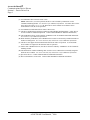
NOTES:
(1) An ATB/DOS driver named *.BIN exists.
(2) An ATB/Win16 driver named *.WBN exists.
(3) An ATB/Win16 driver named *.DLL exists.
(4) An ATB/OS2 driver named *.DLL exists.
cfSOFTWARE Confidential, 2000
Across the Boards
Communications Device Drivers
Section 1 - Device Driver List
Page 6
(5) An ATB/Win32 driver named *3.DLL exists.
NOTE: Unless note (T) is also specified, this driver can be loaded by ATB/Win16 via the
CFXNTGT thunking module. See Section 5.8 for additional information. If a Win16 driver of the
same driver also exists (“2” or “3”), the Win32 driver can be loaded via an alternate device
name/number if note (H) is also specified.
(6) An ATB/DOS extended DOS driver named *.DLL exists.
(9) This driver number/name assigned to ATB/Unix and ATB/Mac implementations. (These drivers
are not available as standard components. Contact cfSOFTWARE for additional information.)
(D) This ATB/Win16 driver can be loaded by ATB/DOS via the CFXVXDT/CFXVXDS mechanism.
See Section 5.13 for additional information.
(H) When loaded by ATB/Win16, this ATB/Win32 driver must be referenced by another XAPI driver
number or Dialog name. See entries with note (W), and Section 5.8 for additional information.
(S) This driver can support both structured field and non-SF modes of operation. A second XAPI
device number is assigned for the alternate mode of operation.
(T) Unlike most ATB/Win32 drivers, this driver cannot be loaded by ATB/Win16 via the CFXNTGT
thunking module.
(W) This XAPI driver number and Dialog name is used to access a Win32 driver normally assigned a
different device number. See entries with note (H), and Section 5.8 for additional information.
(Y) Special use driver. Contact cfSOFTWARE for additional information.
(Z) Driver unavailable as of 02/01/00. Contact cfSOFTWARE for additional information.
cfSOFTWARE Confidential, 2000
Across the Boards
Communications Device Drivers
Section 1 - Device Driver List
Page 7
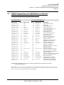
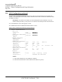
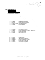
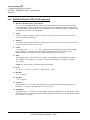
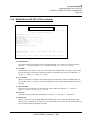
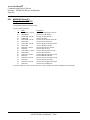
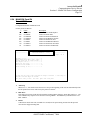
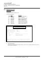
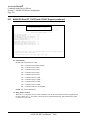
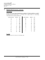
1.1
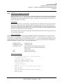
pcMAINFRAME 3.x Device Codes
pcMAINFRAME Version 1.x - Version 3.x used a one character code to refer to various Across the Boards
device drivers (ATB/DOS only). The assignments are shown below:
Device Driver
Name
ATB
dvc#
DIALOG
dev(name)
CFXASNC.BIN
CFXIRMA.BIN
CFXPCOX.BIN
CFXPC3X.BIN
CFXFORT.BIN
CFXIDEX.BIN
CFXITTX.BIN
CFXIBMX.BIN
CFXASTX.BIN
CFXPROX.BIN
CFXMPLS.BIN
CFXPATH.BIN
CFXSPEC.BIN
CFXLV3X.BIN
CFXHLLX.BIN
CFXDECX.BIN
CFXVINX.BIN
CFXXIRC.BIN
0
1
2
3
4
5
6
7
8
9
10
11
12
13
14
16
20
32
--IRM
PCO
327
FOR
IDE
ITT
IBM
AST
PRO/3101
MIC
PAT
SPE
LEV/API
ENT/HLLAPI
VT1/DEC
BAN/VIN
XIR
pcMF3
ID
A
1
2
3
4
5
6
7
8
C
9
P
X
L
H
V
B
I
Description
Async (pcMF Version 1.x-3.x only)
Irma/Irma2/Irma3
PCOX/CXI
IBM 3270PC/Workstation
Forte
IDEA Card
ITT
IBM 3278/9 CUT
AST Remote
IBM 3101 Protocol Converter
MicroPlus
Pathway/ICOT Remote
Special
IBM Level 3.0 (PSAPI)
DOS HLLAPI (IBM Level 1.0)
DEC VT100 Protocol Converter
Banyan VINES
Xircom Pocket 3270
cfSOFTWARE Confidential, 2000
Across the Boards
Communications Device Drivers
Section 1 - Device Driver List
Page 8
cfSOFTWARE Confidential, 2000
Across the Boards
Communications Device Drivers
Section 2 - Across the Boards Memory Sizes
Page 9
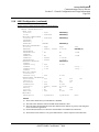
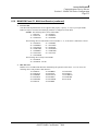
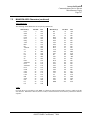
Section 2 - Across the Boards Memory Sizes
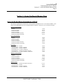
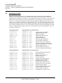
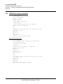
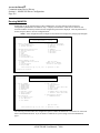
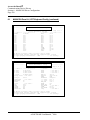
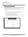
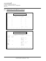
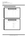
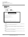
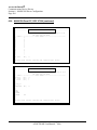
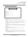
Across the Boards Memory Overhead (as of 6/24/93)
The memory requirements are listed for the various possible combinations of Across the Boards modules. Note
that for OS/2 and Windows the sizes of both the linked-in and DLL versions of Across the Boards are listed.
MS-DOS Linked Modules
CFXAPI
CFXAPI+CFXAPPX
CFXAPI+CFXDIAL
CFXAPI+CFXDIAL2
CFXAPI+CFXAPPX+CFXDIAL
CFXAPI+CFXAPPX+CFXDIAL2
33,520
60,368
88,576
78,176
109,136
98,736
OS/2 Linked Modules
CFXAPI
CFXAPI+CFXAPPX
CFXAPI+CFXDIAL
CFXAPI+CFXDIALW
CFXAPI+CFXAPPX+CFXDIAL
CFXAPI+CFXAPPX+CFXDIALW
24,794
51,287
78,152
49,990
98,872
76,998
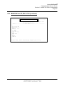
OS/2 DLLs
CFXATBXX.DLL - CFXAPI
CFXATBAX.DLL - CFXAPI+CFXAPPX
CFXATBXD.DLL - CFXAPI+CFXDIAL
CFXATBXW.DLL - CFXAPI+CFXDIALW
CFXATBAD.DLL - CFXAPI+CFXAPPX+CFXDIAL
CFXATBAW.DLL - CFXAPI+CFXAPPX+CFXDIALW
25,050
51,994
78,858
50,698
99,514
77,642
Windows Linked Modules
CFXAPI
CFXAPI+CFXAPPX
CFXAPI+CFXDIALG
CFXAPI+CFXDIALW
CFXAPI+CFXAPPX+CFXDIALG
CFXAPI+CFXAPPX+CFXDIALW
38,663
65,582
97,116
63,635
117,740
90,547
Windows DLLs
CFXATBAD.DLL - CFXAPI+CFXAPPX+CFXDIALG
CFXATBXX.DLL - CFXAPI
CFXATBAX.DLL - CFXAPI+CFXAPPX
CFXATBXD.DLL - CFXAPI+CFXDIALG
cfSOFTWARE Confidential, 2000
119,719
40,839
67,655
99,191
Across the Boards
Communications Device Drivers
Section 2 - Across the Boards Memory Sizes
Page 10
cfSOFTWARE Confidential, 2000
Across the Boards
Communications Device Drivers
Section 3 - General Information
Page 11
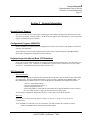
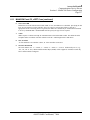
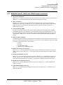
Section 3 - General Information
General Device Support
The Across the Boards device-drivers that work through 3270 emulation all support the Model-2 devices with
24 lines of 80 columns (1920 byte buffers). Some drivers also support other 3270 Models (3, 4 and 5) and some
support extended attribute bytes (EABs).
Configuration Program - MAINCON
MAINCON.EXE is provided to generate configuration files for the device drivers. This module is menu driven
and fairly self-explanatory.
Some of the device drivers require MAINCON to be run in order to function properly. If the DRIVER does
allow/require configuration, the MAINCON menu will list it.
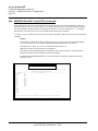
Keyboard Layout for Manual Mode 3270 Emulation
Select entry A1 of the MAINCON menu to configure keyboard and video monitor usage. The entry allows you
to assign key and Alt_, Ctrl_, and Shift_ key combinations as special 3270 keys (Enter, PF1-24, Clear, up/dn
arrows, etc.). The default keyboard layout is that of Irma’s E78.
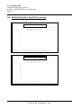
3270 Controllers
IBM 3274 and 3276
Some of the older IBM 3274 controllers do not transmit the ASCII carat (^ hex 5E) character; they send a dash
(hex 2D) instead. This causes APPX applications to get an error #221 (“DUPLICATE CHARACTER...”) in
PPX_MESSAGE at CONNECT time. To correct his problem use the MAINCON configuration program:
- select A1 (Video Monitor Mode ...)
- set the Keyboard Language field to “9”
- save the configuration via F10
- when using APPX, be certain that the configuration file produced, MAINCFG.VDT, is either in
the current disk directory or in the directory pointed to by PPX_PATH.
As of 02/09/93, Configuration Support D Version 65.1 is the current microcode for the 3274.
IBM 3174
For 3174 Asynchronous Emulation Adapters (AEAs), see Section 5.1 Protocol Converter Special
Considerations.
To use the IBM 3174 controller or any 3174 look-alike, you must customize the controller as follows:
FILE TRANSFER AID 125. Miscellaneous Feature Option
cfSOFTWARE Confidential, 2000
Across the Boards
Communications Device Drivers
Section 3 - General Information
Page 12
3270 Controllers (continued)
The FILE TRANSFER AID bit (.... .1..) must be ON. That means that hex 04 must be ORed to any
other value desired for Feature 125.
NOTE: The new IBM 3174 Model 90R microcode B Version 2.0 has a bug that causes it NOT to
honor the TRANSFER AID bit. You must apply patch PTR 9032 from IBM to fix this problem.
The problem manifests itself as no data being transfered from the 3270 buffer to the mainframe -only the AID key is sent to the host.
Even on 3174-90R microcode releases that do support the file-transfer-aid bit, it is not documented
in any of the 90R documentation. The general 3174 manuals describe the option, but the 90R
specific documentation describes the entire option 125 field as “Reserved, leave at default values”
(0000 0000).
IBM 4700
The IBM 4700 controller used by banking systems appears to work the same as a 3274 for ATB purposes in
many configurations. In some configurations, the 3174 equivalent of the “File-Transfer AID Bit” is not
implemented. These 4700’s will run with DIALOG, but APPX or any application that attempts to copy directly
to the presentation space will fail.
It appears that at least one “standard” configuration on the 4700, while otherwise emulating a CUT 3174,
requires different scan codes. A MAINSCAN.SC4 has been created and can be loaded by CFXIBMX,
CFXIRMA, and CFXFORT drivers after 05/03/91. Specify “4” as the alternate keyboard scan code buffer
suffix in MAINCON. The major symptom is CLEAR and other function keys not working in DIALOG.
Integrated Controller
The IBM 4361 mainframe’s integrated controller may translate the character “{“ (ASCII 7B hex and EBCIDC
C0 hex) to hex 00. This can be fixed by zapping MAINCFG.VDT, changing the byte at +11 hex into the file
from 7B to something like 5B (“[“).
AT&T 6544
It seems that the AT&T 6544 is mistranslating or not sending certain data.
Memorex Telex Controllers
Memorex/Telex controllers have the equivalent of the 3174 File-Transfer-Aid bit. There is a global (default)
setting, as well as a per-terminal configuration screen.
Non-English Controllers
Some controllers configured for languages other than English require that CUT mode devices send different
keyboard scan codes. CFXIBMX, CFXIRMA, and CFXFORT drivers after 05/03/91 can use an alternate
keyboard scan code table (a MAINSCAN.SC? file). Specify the suffix of the alternate keyboard scan code table
in MAINCON. The major symptom is function keys not working or keys causing inappropriate actions or
characters.
The following MAINSCAN.SC? files are available:
File Name
MAINSCAN.SC4
MAINSCAN.SCS
Suffix (used in Maincon)
4
S
Usage
4700 (see above)
Spanish controllers
cfSOFTWARE Confidential, 2000
Across the Boards
Communications Device Drivers
Section 3 - General Information
Page 13
Flicker
CICS 1.7 XA MRO-ed terminals
In CICS 1.7 XA with MRO-ed terminals, there is substantial flicker of the system wait X. This can cause the
assumption of a completed message and free keyboard when in fact there is more data coming from the
mainframe. A ZAP is available for the CUT mode modules: CFXIRMA, CFXFORTE, and CFXIBMX.
Contact cfSOFTWARE if you think this problem has arisen.
Example ZAP
DEBUG CFXdddd.BIN
2- e ds:1A7
- xxxx:01A7 19.00
- xxxx:01A8 00.02
-w
-q
[where dddd is Irma/FORT/IBMX]
[enter as shown and press CR]
[replace 19 with 00 and press space bar]
[replace 00 with 02 and press CR]
[press w to write .BIN file to disk]
[quit debug]
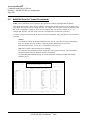
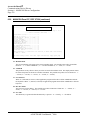
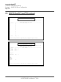
Field Attributes
3270 Attributes
PC Color
PC Mono/B&W
normal unprotected
normal protected
bright unprotected
bright protected
dark (non-display)
green
cyan
red
white
(blank)
grey
grey
white
white
(blank)
5250 Attributes
PC Color
PC Mono/B&W
normal in/out
normal column-separator
bright in/out
bright column-separator
dark (non-display)
underscore
reverse
green
cyan
red
cyan
(blank)
(ignored)
(ignored)
grey
grey
white
grey
(blank)
(ignored)
(ignored)
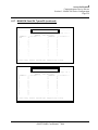
VT100 Attributes
PC Color
PC Mono/B&W
normal
reverse
underscore
bold
blink
dark (non-display)
green
cyan
red
white
white
(blank)
grey
grey
white
grey
grey
(blank)
IBM 3101 Attributes
PC Color
PC Mono/B&W
normal unprotected
normal protected
bright unprotected
bright protected
(any others)
dark (non-display)
green
cyan
red
white
green
(blank)
grey
grey
white
grey
grey
(blank)
cfSOFTWARE Confidential, 2000
Across the Boards
Communications Device Drivers
Section 3 - General Information
Page 14
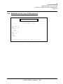
CICS Terminal Definition
A critical factor in the use of 3270 terminals is the size of the terminal I/O area. This is defined in the TIOAL
parameter in the TCT entry or in the IOAREALEN parameter of the TYPTERM entry if RDO is used to define
terminals.
If the device is non-SNA the value specified should be at least as large as the maximum message that will be
sent to the device. For Model 5 devices, 4000 must be specified.
For SNA devices two parameters are specified, the chain size and the maximum size. The value 256,4000 would
be appropriate for all devices.
We have encountered ATNI abends in cases where too small a TIOAL is specified.
cfSOFTWARE Confidential, 2000
Across the Boards
Communications Device Drivers
Section 4 - Device Driver Configuration and Usage
Page 15
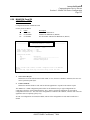
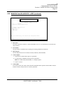
Section 4 - Device Config.
Not Available Online
cfSOFTWARE Confidential, 2000
Across the Boards
Communications Device Drivers
Section 4 - Device Driver Configuration and Usage
Page 176
cfSOFTWARE Confidential, 2000
Across the Boards
Communications Device Drivers
Section 5 - General Configuration and Usage Information
Page 177
Section 5 - General Configuration and Usage Information
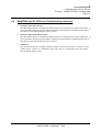
5.1
Protocol Converter 3101 and VT100
- Special Considerations
Converter Quirks
The following list must be considered a small fraction of the total selection of protocol converters. In addition,
due to constant changes and RPQs to converter hardware and software for the same brand/model this quirk list
may not be valid. Expect the worst.
IBM Series 1 (Yale ASCII Package)
- uses backspace (08 hex) as ENTER key
- no flow control (no XON/XOFF)
- loses data when overrun (CFXPROX auto-resend AID sometimes corrects)
IBM 7171
- channel attached (sends data to screen out of sequence) (may need DIALOG LINEDROP
to disconnect)
- uses backspace (08 hex) as ENTER key
- no flow control on some models (no XON/XOFF)
- loses data when overrun (CFXPROX auto-resend AID sometimes corrects)
(ROM chip update is available from IBM that allows 1500 byte blocks as of 01/88)
- if bytes are being dropped, try using KEYDELAY set to 50 millisecs
IBM 7626
- SNA only. Little box, a poor 4 line converter
- uses backspace (08 hex) as ENTER key
- no flow control (no XON/XOFF)
- loses data when overrun (CFXPROX auto-resend AID sometimes corrects)
IBM 3708
- should be configured with “medium” size buffer
- flow control is optional (not needed with medium/large size buffer). The 3708 should be
configured to not send XOFF/XON pairs as punctuation of the data stream
- BEL issued for line errors (locks keyboard till RESET). If the 3708 is in file-transfer mode, this
lock will not happen. Esc > to enter file-transfer mode and Esc < to turn it off
IBM 3174 with Async Adapter (up 32 lines)
- cannot configure buffer size
- has XON/XOFF flow control
- we have tested up to 19.2
- cannot upload effectively. Due to small input buffer size data transfer upload forces many
many XOFFs
cfSOFTWARE Confidential, 2000
Across the Boards
Communications Device Drivers
Section 5 - General Configuration and Usage Information
Page 178
5.1
Protocol Converter 3101 and VT100 (continued)
IBM AS/400 - VT100 protocol conversion
The AS/400 places asterisks in column 80 from row 9 down to simulate terminal lights or some such thing. This
disrupts data transfer.
NOTE: To turn off this asterisking, send ESC ^W (hex 1B 17) from the PC to the AS/400 before
doing any data transfer or APPX CONNECT COMTEX.
- has only an 8 byte input buffer
- is easily overrun
- loses data when overrun (CFXPROX auto-resend AID sometimes corrects)
- later releases of this converter solve some of the above
Hydra
Channel attached (sends data to screen out of sequence).
NOTE: May have trouble with 9600 bps UPLOAD (losing data or Enter key). If so, run at 4800 bps
or use a 2 millisecond KEYDELAY via MAINCON.
NOTE: Has trouble with ASCII 7D hex ‘}’ and 7B hex ‘{‘ Hydra fails to translate properly to
EBCDIC:
ASCII 7Dh should translate to EBCDIC x’D0’ (zone-decimal -0).
ASCII 7Bh should translate to EBCDIC x’C0’ (zone-decimal +0).
The Fix:
The Hydra should already be set for device type IBM 3101 or VT100. Use the Ctrl_Y menu on Hydra
to fix the XATE table.
- PF1 (Esc a) cycle through commands till “DSPLY”
- tab to 2nd field
- PF1 cycle through commands to “XATE” ASCII to EBCDIC
- press ENTER (CR) to show table
- change at offset +7D from 7D to D0 at offset +7B from 7B to C0
- PF2 (Esc b) to “LOAD”
- press ENTER -- should load OK
- PF1 in first field till “RESET”
- tab to second field
- PF1 in second field till “ALL”
- press ENTER to reset all
NOTE: The RESET ALL will cause all connected lines to DISCONNECT.
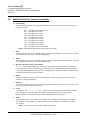
Sample Hydra control menu for fixing XATE table. Note change table at offset +7D from 7D to D0 and at offset
+7B from 7B to C0: Hydra-II DSPLY XATE DFLT 4.51B, V=5.
The (SNA or non-SNA) Hydra may be set to place an asterisk at row 1 column 80 as a LOCK-X substitute.
When the LOCK-X turns off, the asterisk is replaced with a space instead of the character originally overlaid by
the asterisk. Naturally, this causes data transfer errors. This problem seems to be dependent on whether the
Hydra is attached via BTAM or VTAM. It functioned correctly under BTAM and failed when the system was
converted to VTAM. In comparing the traces, under BTAM the asterisk was replaced before the second send of
the confirmation character was done.
cfSOFTWARE Confidential, 2000
Across the Boards
Communications Device Drivers
Section 5 - General Configuration and Usage Information
Page 179
5.1
Protocol Converter 3101 and VT100 (continued)
Under VTAM the confirmation send was done before the asterisk was replaced. It appeared that the asterisk
was always replaced with a blank in both environments which should have caused a problem, but the trace
sample was small and it may have been that the data byte was in fact always a blank.
To fix this problem:
- Bring up the Terminal Definition screen of the SNA Hydra
- Set the KLCK and VNL fields to hex FF to prevent the asterisk
NOTE: In some releases of Hydra software the VNL field is renamed as KUNL. It should be set to
hex FF as well).
- firmware release for Hydra 5.08 is fine, but when file transfers are attempted with firmware
5.20, escape sequences get trashed at random intervals (characters lost), resulting in disconnect
request, and timeout
NetLink
- assumes auto-wrap for the 3101 (when it sends CRLF, it means CRLF) configure
(MAINCON) this converter with AUTO-WRAP on
- BEL and echo-back are out of sync making recovery from jam difficult
- slow
Kaufman
- fixed terminal type by port (hardware)
- purchased by AVATAR
- clean
PCI
- sends <WAIT> to upper left during system lock
- clean
IrmaLINE
- 3274 coax attached (sends data to screen out of sequence)
- sends cursor positioning (4 bytes) for each byte echoed
- uses line 24 as OIA
- slow
Avatar <VT100 only>
- 3274 coax attached
- The AVATAR does not support IBM 3101 terminal protocol. Therefore, it will not function with
CFXPROX. It requires CFXDECX
Wall Data
- can be set for 3101 via configuration default or startup menu.
- OIA optionally on line 24
- XON/XOFF byte values configurable
- Keyboard totally configurable (requiring PROX_KEY_TABLE)
- Auto baud rate recognition (may require several blanks to be sent after “CONNECT” in order
to make this recognition)
cfSOFTWARE Confidential, 2000
Across the Boards
Communications Device Drivers
Section 5 - General Configuration and Usage Information
Page 180
5.1
Protocol Converter 3101 and VT100 (continued)
Data Stream
- Works only with Data-Stream microcode versions above 2.0. (A ROM upgrade may be required)
Data Lynx
- Do not load TERMLYNX TSR software (grabs COMM port interrupt) or use program
UNCLINK to cause TSR to release COMM port (program CLINK re-establishes it for TSR).
- otherwise works well as 3101
Micom
- channel attached (sends data to screen out of sequence) (may need DIALOG LINEDROP to
disconnect)
- XON may be configured as end-of-message on some models (this should be changed to CR)
- 7400-74016 model cannot upload faster than 2400 baud. To use 9600 for both up/download set
KEYDELAY in configuration to 4 millisecs
- download clean at speeds up to 9600 baud
Renex
- fast
- RTD model works. Uses Esc Esc sequences for native mode controls. For 3101 still uses
EscEsc R for reset (but Esc L for clear).
- handles up to 9600 bps upload when channel attached
Lee Data
- Model 8010 allow upload at 9600
- works up/download at 2400bps -- no problems as 3101
- ^Z as clear key
- will pass { as data byte
CXT
-
Not tested yet
Black Box
- Model A/C(3B) (ASCII to coax) required KEYDELAY of 50 millisecs to prevent losing data
on upload. No flow control.
- Model ??? (370x connected) is reputed to be running OK somewhere
Carterphone
- to date, we have not gotten data transfer through this box
Simware’s VT100 protocol converter
- Simware has mainframe software (VTAM, VM, etc) that functions as a protocol converter.
Rabbit VT100 protocol converter software
- runs as VT100 only (no 3101)
- runs on IBM RT under Unix using DFT coax connect to host and multiple serial inputs
- must configure for VT100 with AUTOWRAP = 2. The Rabbit software sends CRs and means
just that -- CR
cfSOFTWARE Confidential, 2000
Across the Boards
Communications Device Drivers
Section 5 - General Configuration and Usage Information
Page 181
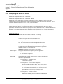
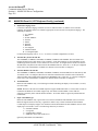
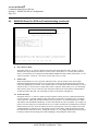
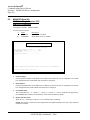
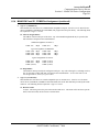
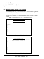
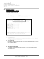
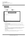
5.2
Configuring the Telnet TN3270 Drivers
MAINCON Configuration Panel: E1: “Telnet TN3270”
MAINCON Configuration Panel: E7: “Telnet TN3270 with TN3287”
Configuration of Telnet TN3270 Drivers
If MAINCON is not used to configure the Telnet TN3270 drivers, the driver will run as a basic (non-enhanced,
non-SF) 3270 Model 2, with no TCP/IP trace and using the Telnet Well-Known-Port as the default (#23).
MAINCON can be used to configure the TN3270 drivers to support 3270 Models 2, 3, 4 and 5. If the host is
capable of it, the enhanced 3270 support, which includes EABs and structured field support, can be configured
by configuring the 3270 model as 2E, 3E, 4E or 5E. Enhanced 3270 support must be configured if structured
field support is required (for example in APPX). If the driver is configured for enhanced 3270 support both the
SF and non-SF APPX connections are available. Only the non-SF APPX session is available with basic 3270
support.
NOTE: Most TN3270 hosts support the enhanced 3270 terminals.
MAINCON can be used to enable a trace of the TCP/IP activity between the driver and the host. Entering a
trace size other than zero will enable the trace. The trace data is kept in a circular buffer and will be written
when the driver is closed. A file called TCPTRAC.BUF will be produced in the current directory. The program
TRACEFMT.EXE will format the TCPTRAC.BUF file.
MAINCON can also be used to alter the default destination port on the host. If nothing is entered, MAINCON
will default to the Telnet Well-Known-Port (#23).
MAINCON can also be used to set “disconnect at denegotiate” mode. When enabled, this mode forces the
Telnet session to disconnect whenever a host action that would normally only cause a drop to NVT mode
occurs.
See Section 6.21 for additional TN3270 configuration options.
Operation of Telnet TN3270 Drivers
These drivers implement all TN3270 functions including NVT mode if the host does not support TN3270. A
new MAINCON configuration panel exists to support these drivers. This allows the configuration of terminal
type (3270 Models 2, 3, 4 or 5, with or without EABs and structured field support), the size of the internal trace
buffer, and the default destination port address to use if the Telnet well-known-port is not being used.
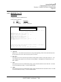
When first opened, the drivers display an NVT screen with a message requesting entry of the host name or
address. The NVT screen consists of one enterable line (at the bottom), and a scrolling message area above the
enterable area. Model 3270 field attributes are emulated on the NVT screen by the driver. The OIA indicates if
the driver is disconnected (“disc” at the beginning of the OIA), in NVT mode (“NVT”) or in a TN3270 session
(“TA#” for the LU-LU session or “TA?” for the SSCP-LU session).
Section 5.4. TCP/IP Host Names and Addresses describes the addresses that can be entered to connect to a host.
In addition, when connecting to a TN3270E host, an LU name may be requested. This is done by coding the
reqested LU name on the host name line after a colon.
Example:
CF370.CFSOFT.COM :LU2T0001 - Requests LU “LU2T0001”
The ApkTest key causes the driver to disconnect from the host and return to disconnected NVT mode.
In NVT mode, the ApkPF12 key functions as a “retrieve” key, and will redisplay recently entered items.
cfSOFTWARE Confidential, 2000
Across the Boards
Communications Device Drivers
Section 5 - General Configuration and Usage Information
Page 182
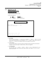
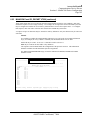
5.2
Configuring the Telnet TN3270 Drivers (continued)
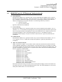
Configuration of Telnet TN3287 Support
In addition to the TN3270 options described above, the “TN3270 with TN3287” drivers support several
configuration options related to printer support. There is a second MAINCON configuration panel for the
TN3287 driver which contains the additional options.
MAINCON can be used to alter the following behaviors: default print routing, when the printer session connects
to the host, how a failure of the printer session is dealt with, whether or not the operator may specify a specific
printer session to use (rather than the one associated with the operator’s terminal by the host), how print output
is formatted, operation of the local copy functions, and compensation for incorrect host (TN3270 server)
behavior.
See Section 6.27 for additional TN3270/TN3287 configuration options.
TN3287 Operation
In most respects, the presence of the printer session is transparent to the base terminal session. The following
differences exist:
There are six additional “keys” defined which have are processed by the TN3287 session.
DskTN3287_Enter:
DskTN3287_Test
DskTN3287_Cancel
DskTN3287_PA1/2
DskTN3287_ClosePrint:
Start print session (if not connected)
Drop printer session
Discard data in print buffers (SCS mode only)
Send PA1/2 sequence to host (SCS mode only)
Close printer output
The PA1, PA2 and Cancel keys replace the switches of the same name usually found on a 3270 printer. The
Enter and Test keys will start and stop the printer session with the host (note that by default the printer session
will automatically be started). The ClosePrint key closes the output file, and will release output for printing in
environments where a print spooler is used (note that the driver automatically closes the print output file when
the host indicates that the print job is complete, but the “EOJ” is not always signaled).
The OIA of the base terminal contains a printer status section, which may contain the following:
P-Off: Printer session disabled by (local) application
P-Err: Printer error occurred
P-Disc: Printer not connected to host (DskTN3287_Enter to start)
P-Fail: Printer tried to connected to host, but failed (DskTN3287_Enter to retry)
P-Conn: Printer connecting to host
P-Rdy: Printer connected to host, waiting for work
P-Busy: Printer busy printing
NOTE: local copies (both host and operator initiated) do not, by default, require a host connection for the
printer session. Operator initiated local copies require that the printer not be busy (host initiated local copies are
queued if the printer is busy when the request is received).
cfSOFTWARE Confidential, 2000
Across the Boards
Communications Device Drivers
Section 5 - General Configuration and Usage Information
Page 183
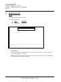
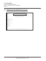
5.2
Configuring the Telnet TN3270 Drivers (continued)
The ApkPrint base terminal key will initiate a local copy operation.
When the host name is entered, a specific printer LU may be requested. The syntax is:
hostname [port] [:[luname][/prtluname]
Examples:
Request LU “LU2T0001” (with associated printer):
CF370.CFSOFT.COM :LU2T0001
Request LU “LU2T0001” with specific printer “LUPRT1”
CF370.CFSOFT.COM :LU2T0001/LUPRT1
Request any LU with printer “LUPRT1”
CF370.CFSOFT.COM :/LUPRT1
While printing is in progress, a “cancel” dialog box is displayed. Selecting “Cancel” will discard the current
unit of output from the host. (The dialog box may be suppressed by the local application).
The WPCTL1 printer device control string is supported (XAPI function). The following fields of the WPCTL1
control string are active:
bEnable
- TRUE if printer is enabled
fPrint
- Print selection flags
#define WPC_PSELDEFAULT
(0x0000)
#define WPC_PSELMAINCON
#define WPC_PSELSPECIFIC
fDialogBox - Dialog Box options
#define WPC_USEDIALOGBOX
#define WPC_NODIALOGBOX
(0x0001) (treated as WPC_PSELDEFAULT)
(0x0002)
(0x0000)
(0x0001)
fFontOpt
- Font options
#define WPC_DEFAULTFONT
(0x0000)
#define WPC_LOGFONT (0x0001)
fEOJ
- EOJ control flags
#define WPC_EOJIDLE (0x0002)
IdleTimeout - Print idle timeout
szDriver
- Print driver to select (2nd parameter of CreateDC)
lf
- Logical font structure
szCaption
- Caption for printer dialog boxes
See CFXCTLS.H for additional documentation on these fields.
cfSOFTWARE Confidential, 2000
Across the Boards
Communications Device Drivers
Section 5 - General Configuration and Usage Information
Page 184
5.3
Configuring the Telnet VT220 Drivers
MAINCON Configuration Panel: E2: “Telnet VT220”
MAINCON must be used to configure the Telnet VT220 drivers.
With the exception of the first panel, the MAINCON configuration for the Telnet VT220 drivers is identical to
that of the async/serial VT220 driver. This Section describes only the differences in the Telnet VT220
configuration.
The following options are not present in the Telnet VT220 configuration: XON/XOFF character, Keystroke
Delay, COMM port, Line Speed, Line Parity, Data Bits, and Stop Bits. Most of these are irrelevant to a Telnet
connection (for example, Line Speed), while the others are replaced by Telnet internal functions (for example,
flow control is handled by TCP and Telnet, and not the XON/XOFF mechanism).
The Autowrap, Reset After BELL, Flicker Check Time, and Half Duplex options provide the same functions as
the async VT220 driver.
NOTE: If Half Duplex is configured the driver will refuse any attempt by the host to enter Telnet full
duplex mode.
The following new configuration options are added to the Telnet VT220 driver:
MAINCON can be used to enable a trace of the TCP/IP activity between the driver and the host. Entering a
trace size other than zero (the default) will enable the trace. The trace data is kept in a circular buffer and will
be written when the driver is closed. A file called TCPTRAC.BUF will be produced in the current working
directory. The program TRACEFMT.EXE will format the TCPTRAC.BUF file.
MAINCON can be used to alter the default destination port on the host. If nothing is entered, MAINCON will
default to the Telnet Well-Known-Port (#23).
MAINCON can also be used to force the driver to negotiate “Binary” mode. Binary mode prevents the host
from interpreting the standard NVT control characters. Some hosts require this mode. This should usually be
configured as “ASCII” (the default).
Operation of Telnet VT220 Drivers
These drivers implement all Telnet and VT220 functions including NVT mode. A new MAINCON
configuration panel exists to support these drivers. This allows the configuration of VT220 options, the size of
the internal trace buffer, the default destination port address to use if the Telnet well-known port is not being
used, and whether or not the driver should negotiate binary mode.
When first opened, the drivers display an NVT screen with a message requesting entry of the host name or
address. The NVT screen is a scrolling TTY-like display.
cfSOFTWARE Confidential, 2000
Across the Boards
Communications Device Drivers
Section 5 - General Configuration and Usage Information
Page 185
5.4
TCP/IP Host Names and Addresses
The Telnet drivers accept host names or addresses entered via the keystroke functions while in disconnected
state or via the TELNETCON control string. This may be an IP “dotted-decimal” address or the name of the
host to be resolved via the /etc/hosts file or the name service in use. Optionally the address or name may be
followed by the TCP port number to connect to on the host. The default port is the well-known port for Telnet
(port #23). The default port number may be changed in MAINCON.
Samples:
208.200.57.140
CF370
CF370.CFSOFT.COM 125
208.200.56.81
Connect to host at 208.200.57.140, port 23
Connect cf370 host, port 23
Connect to cf370.cfsoft.com host, port 125
Connect to host at 208.200.56.81, port 23
cfSOFTWARE Confidential, 2000
Across the Boards
Communications Device Drivers
Section 5 - General Configuration and Usage Information
Page 186
5.5
Multiple COMM Port and Modem Server Support in Across the Boards/DOS
MAINCON Configuration Panel: D1: “Comm Port Assignments”
Version 3.06 of Across the Boards adds support for multiple COMM ports (ports beyond COM1 and COM2)
and NASI and INT 14 based modem servers (also known as async gateways). A new MAINCON configuration
screen allows the configuration of COM1 through COM15. If no special configuration is entered for COM1 or
COM2, the standard PC COM1 and COM2 ports are accessed. Accessing other COMM ports requires
configuration.
Multiple COMM Port Support
Version 3.06 of Across the Boards includes support for async serial ports above “COM2”. Prior versions were
limited to either COM1 or COM2. To configure an extended serial port, the following steps are required:
1.
2.
3.
4.
As has been done in the past for serial communications, select option “D2”, “D3”, or “D4” from
MAINCON’s primary menu (for IBM 3101, VT100, or Tymnet78 support respectively).
The configuration screen for the chosen protocol converter will appear. For the “COMM port”
specification, specify “3” to “15”. Press F10 to write the configuration file; this will return you to
the primary menu. (Alternatively, the COMM port may be specified at the XAPI open or in a
DIALOG script).
Select option “Communication Port Assignment” from the primary menu (D1).
In the configuration line corresponding to “COM3” (or whichever port was configured in step 2),
enter “COMM” in the TYPE field. You will be presented with two additional fields: “I/O Port”,
and “IRQ”. The appropriate values for these fields vary by hardware configuration; a help screen
may be obtained by pressing F1 which presents guidelines for configuration.
Enter the appropriate values in these fields, then press F10 to write the configuration file.
The configuration is then completed.
NOTE: It is possible to alter the I/O port and interrupt assignments for COM1 and COM2, but this may
lead to confusing configurations and is therefore not recommended (for example, the user could swap
COM1 and COM2). If no special configuration is supplied for COM1 and COM2, the standard values
will be used.
Configuring NASI (NetWare Async Services)
NASI based modem servers (available from Novell and numerous other vendors), use an INT 6B API.
Configuration for NASI is similar to the preceding example with the following exceptions:
1.
2.
3.
The choice of COMM port is not significant (1-15 may be used).
On the “Communication Port Assignments” configuration screen, specify type “NASI” for the
COMM port you have chosen.
You will then be prompted for “Name”, which must be the resource name for the NASI server.
Contact your LAN administrator for this information.
Configuring INT 14 Drivers
INT 14 based modem servers use a variant of the PC-BIOS INT 14 serial port API. Most vendors provide their
own extensions to the BIOS INT 14 API. Across the Boards can be configured to take advantage of some of
these dialects.
cfSOFTWARE Confidential, 2000
Across the Boards
Communications Device Drivers
Section 5 - General Configuration and Usage Information
Page 187
5.5
Multiple COMM Port and Modem Server Support (continued)
Configuration for INT 14 is similar to the preceding examples with the following exceptions:
1.
2.
3.
Again, the choice of COMM port is not significant (1-15 may be used).
On the “Communication Port Assignments” configuration screen, specify type “INT14” for the
COMM port you have chosen.
You will then be prompted for a “Port” and a “Dialect”. The Port will be the port number
specified to the INT 14 interface. Usually the INT 14 redirector software (included with the
modem server software) allows the configuration of a particular COMM port to redirect. This is
the port number to configure here. The Dialect field should be set to a non-zero value if the INT
14 redirector software implements one of the supported dialects. The following dialects are
currently supported:
0 - Basic INT 14 API
1 - Fresh Technology/Modem Assist
03/17/93. Reported a problem using MODEM_ASSIST Version 2.1. This new version is structured much
differently than earlier versions we have tested. On the server, you run MSERVER; on the client, MCLIENT
CONNECT.
The problem was that the user was running MCLIENT without the CONNECT parm. In this state, Modem
Assist’s test program, TERM, will run just fine but not the INT 14 interface.
NOTE: This new release is not compatible with the old extended INT14 dialect 1 (configurable in
MAINCON). Users of this release must run basic dialect (dialect 0).
cfSOFTWARE Confidential, 2000
Across the Boards
Communications Device Drivers
Section 5 - General Configuration and Usage Information
Page 188
5.6
VTAM/NCP Issues for Across the Boards
5.6.1
Buffer size problems in cfDFT and other structured field drivers
Environments generating SNA sense codes of X’800A’ (in some drivers, especially cfDFT, reported as
X’0A80’), may have a configuration problem in NCP or VTAM. The sense code is most often
returned after an APPX send operation involving a large structured field. The error is an indication that
the receiver (NCP or VTAM) was unable to handle the PIU, since it was too big. This can be verified
by setting the APPX block size down to 1920, and retrying the connection. It should work.
The problem is in NCP, VTAM or in the destination LU (i.e., CICS). The LU with which the bind was
negotiated has indicated an RU (PIU) size that one of the network components (e.g., VTAM or NCP)
cannot handle. This may be corrected either in the destination LU (by reducing the RU size) or by
increasing the allowed RU sizes in VTAM and/or NCP. Some of the VTAM and NCP parameters that
may need to be changed are listed below:
NCP
MAXDATA
MAXBFRU
VTAM
RACMLUBF (in ISTRACON)
MAXBFRU
It is also possible to alter the MODETAB to specify a smaller RU size.
cfSOFTWARE Confidential, 2000
Across the Boards
Communications Device Drivers
Section 5 - General Configuration and Usage Information
Page 189
5.7
Windows NT CFXNTDD.SYS Installation
CFXIRMA3.DLL (device number 1), CFXIBMX3.DLL (#7) and CFXFORT3.DLL (#4) require that
CFXNTDD.SYS be installed.
NOTE: Drivers 81, 82, 83 are synonyms for 1, 4, and 7.
Run the INSTNTDD.EXE installation program or use the following manual procedure:
5.7.1
Copy CFXNTDD.SYS to \WINNT\SYSTEM32\DRIVERS
5.7.2
Use REGINI to add the items in CFXNTDD.INI to the registry (“REGINI CFXNTDD.INI”)
NOTE: REGINI is available in either the SDK or the NT Resource Kit. It is assumed that the
application’s installation program will install the driver for the end-user.
5.7.3
Use the “Drivers” tool on the control panel to start “CfxNTdd”
5.7.4
You may wish to set “CfxNTdd” to manual startup
5.7.5
When using an Irma 2, Irma 3, Irma 3t
If you are using an Irma 2, Irma 3, Irma 3t or one of the coax cards that requires a microcode load, and
the vendor does not have an NT compatible microcode load program (DCA does not), you will need to
load the microcode outside of NT, probably from a DOS boot diskette.
5.7.6
For pcMAINFRAME installations, program INSTNTGT.EXE must be run (once) to install
CFXNTDD.SYS
cfSOFTWARE Confidential, 2000
Across the Boards
Communications Device Drivers
Section 5 - General Configuration and Usage Information
Page 190
5.8
ATB/Win16 Applications under WOW (Windows-on-Windows)
in Windows NT and in Windows 95
The WOW (Windows-on-Windows) environment of Windows NT provides the capability to run 16 bit
Windows applications under Windows NT. WOW prevents many ATB/Win16 device drivers from running,
either because they access hardware directly or invoke an unavailable API. In many cases CFXNTGT.DLL
makes it possible to access the Windows NT driver instead of the Win16 driver, and thus provide access to a
Windows NT emulator or a emulation card that does not provide an API to the WOW session.
Under Windows 95, direct access to hardware is not prevented, but it may be desirable to use an emulator’s 32
bit API (instead of the 16 bit API, which may not be available in all cases). In many cases, CFXNTGT.DLL
makes it possible to use the ATB/Win32 drivers from an ATB/Win16 application.
The use of an ATB/Win32 driver is mostly transparent to an ATB/Win16 application. When a Win32 driver is
selected at XAPI open time, CFXNTGT.DLL is automatically loaded, and the Win32 driver is accessed
transparently. In most cases the Win32 driver has a unique device name and number that does not conflict with
any Win16 names. In some cases (drivers which access hardware or serial ports directly), the base Win32 driver
name/number is the same as a Win16 driver name/number, and a synonym has been assigned to provide access
to that driver for ATB/Win16 applications.
cfSOFTWARE Confidential, 2000
Across the Boards
Communications Device Drivers
Section 5 - General Configuration and Usage Information
Page 191
5.8
ATB/Win16 Applications under WOW (Windows-on-Windows)
in Windows NT and in Windows 95 (continued)
ATB/Win32 Driver
Driver Name
CFXIRMA3.DLL*
CFXFORT3.DLL*
CFXIBMX3.DLL*
CFX220X3.DLL*
CFXT3WS3.DLL
CFXT3WS3.DLL
CFXWHLL3.DLL
CFXRUMB3.DLL
CFXT2WS3.DLL
CFXEXTW3.DLL
CFX320X3.DLL*
CFXT4WS3.DLL
CFXATWS3.DLL
CFXNSEL3.DLL
CFXWRQI3.DLL
CFXSWFT3.DLL
CFXIBMW3.DLL
CFXIBWS3.DLL
CFX62WC3.DLL
CFX62NS3.DLL
CFX62EP3.DLL
CFX62RU3.DLL
CFXATPP3.DLL
CFX62SS3.DLL
CFX62IB3.DLL
CFXT5WS3.DLL
CFXIBM53.DLL
CFXCA403.DLL
CFXRUM53.DLL
CFXPSPW3.DLL
CFXWSRF3.DLL
CFXBLUE3.DLL
CFXCFMP3.DLL
Accessed in ATB/Win16 as
Dvc #
Dialog Name
1
4
7
33
59
60
75
85
93
95
102
112
122
123
124
125
126
127
130
133
134
135
136
137
138
141
143
144
145
146
147
148
149
IRM
FOR
IBM
VT220
TN3WSOK3
TN3WSOK3
WHLL3
NT-RUMBA
TN2WSOK3
NT-EXTRA
VT320
TN4WSOK3
--NS-ELITE3
WRQI3
SWIFT3
NT-PCOM
NT-PCOM-SF
--------NT-ATCP-PPP
----TN5WSOK3
NT-PCOM5
NT-CA400
NT-RUMB5
NT-PASSPORT
NT-WINSURF
NT-BLUES
---
Dvc #
81*
82*
83*
94*
59
60
75
85
93
95
113*
112
122
123
124
125
126
127
130
133
134
135
136
137
138
141
143
144
145
146
147
148
149
Dialog Name
Description
NT-IRMA
NT-FORTE
NT-IBM
NT-VT220
TN3WSOK3
TN3WSOK3
WHLL3
NT-RUMBA
TN2WSOK3
NT-EXTRA
NT-VT320
TN4WSOK3
--NS-ELITE3
WRQI3
SWIFT3
NT-PCOM
NT-PCOM-SF
--------NT-ATCP-PPP
----TN5WSOK3
NT-PCOM5
NT-CA400
NT-RUMB5
NT-PASSPORT
NT-WINSURF
NT-BLUES
---
WOW Irma/Irma2/Irma3
WOW Forte
WOW IBM 3278/9 CUT
WOW VT220 Async
TN3270 Win32 Sockets non-SF
TN3270 Win32 Sockets
Win32 WOSA HLLAPI
Win32 Rumba for NT
Telnet VT220 Win32 Sockets
Win32 Extra! for NT/95
WOW VT320 Async
Telnet VT320 Win32 Sockets
APPX/TCP Win32 Sockets
NS/Elite for Win32
WRQ Reflection for IBM Win32
NetManage Swift for Win32
Personal Comm (Win32)
Personal Comm (Win32) - SF
WinCPIC LU6.2 Win32
IBM Personal Comm LU6.2 Win32
Extra! LU6.2 Win32
Rumba LU6.2 Win32
APPX/TCP cfPPP Driver (Win32)
SNA Server APPC Driver (Win32)
IBM PCOM APPC Driver (Win32)
TN5250 Win32Sockets
Personal Communications 5250 (Win32)
Client Access/400 5250 (Win32)
Rumba 5250 (Win32)
Zephyr Passport 3270 (Win32)
ICOM WinSurf+ 3270 (Win32)
NewHart Systems Blues Win32)
CFMP Driver for TPNS Handling
*NOTE: under ATB/Win16, this driver has a different DIALOG name and XAPI device number
than under ATB/Win32.
See Sections 4.1, 4.4, 4.7, 4.33, 4.59, 4.60, 4.75, 4.81, 4.82, 4.83, 4.85, 4.93, 4.94, 4.95, 4.102, 4.112, 4.113,
4.122, 4.123, 4.124, 4.125, 4.126, 4.127, 4.130, 4.133, 4.134, 4.135, 4.136, 4.137, 4.138, 4.141, 4.143, 4.144,
4.145, 4.146, 4.147, 4.148, and 4.149 for more information.
cfSOFTWARE Confidential, 2000
Across the Boards
Communications Device Drivers
Section 5 - General Configuration and Usage Information
Page 192
5.9
Identifying HLLAPIs
While this document describes many of the existing Windows and OS/2 HLLAPIs, and the ATB/Win16,
ATB/Win32, and ATB/OS2 drivers to use with them, in some cases the end-user is not sure which 3270
emulator they have installed, or they may have a 3270 emulator that we have not seen before. The various 3270
emulators load various named DLLs to provide their HLLAPI. The following list can be used to determine
which Across the Boards drivers might work with the installed emulator by matching the DLL names from the
emulator to the ATB/Win16, ATB/Win32 or ATB/OS2 driver name. Note that the set of HLLAPI DLL names
overlaps between various emulators, and two emulators providing the same (name) HLLAPI DLL may or may
not be actually providing the same API. Also, many emulators provide more than one HLLAPI DLL, and while
in theory we should be able to support all of them, it is most probable that the native HLLAPI DLL will be the
most stable, and best tested.
HLLAPI DLL name
ATB/Win16 Driver(s) using that name
ACS3EHAP.DLL
AHLLAPI.DLL%
EEHLLAPI.DLL*
EEHLLAPI.DLL*%
EHLLAPI.DLL
HLLAPI.DLL
MMXTX.DLL
OMNIHLL.DLL
PCSHLL.DLL*
PCSHLL.DLL*
PCSHLL.DLL*
WHLLAPI.DLL*
WHLLAPI.DLL*%
WSHLLAPI.DLL
CFXIRMW.DLL
CFXIRM5.DLL
CFXRUMB.DLL
CFXRUM5.DLL
CFXEICO.DLL
CFXEXTW.DLL
CFXDYNC.DLL
CFXOMNW.DLL
CFX147W.DLL
CFXIBWS.DLL
CFXIBMW.DLL
CFXWHLL.DLL
CFXWHL5.DLL
CFXNVLW.DLL
HLLAPI DLL name
ATB/Win32 Driver(s) using that name
EEHLLAPI.DLL*
EEHLLAPI.DLL*%
EHLAPI32.DLL
EHLAPI32.DLL*%
EHLAPI32.DLL*
HLLAPI32.DLL*
HLLAPI32.DLL*
WHLL32.DLL
WHLLAPI.DLL*
WHLLAPI.DLL*
PASSHLL.DLL
PCSHLL32.DLL*
PCSHLL32.DLL*
PCSHLL32.DLL*%
PCSHLL32.DLL*
CFXRUMB3.DLL
CFXRUM53.DLL
CFXRUMB3.DLL
CFXRUM53.DLL
CFXEXTW3.DLL
CFXBLUE3.DLL
CFXWRQI3.DLL
CFXSWFT3.DLL
CFXWHLL3.DLL
CFXNSEL3.DLL
CFXPSPW3.DLL
CFXIBMW3.DLL
CFXIBWS3.DLL
CFXIBM53.DLL
CFXWSRF3.DLL
(#26)
(#92)
(#29)
(#91)
(#30)
(#25)
(#34)
(#53)
(#80)
(#55)
(#31)
(#52)
(#84)
(#50)
(#85)
(#145)
(#85)
(#145)
(#95)
(#148)
(#124)
(#125)
(#75)
(#123)
(#146)
(#126)
(#127)
(#143)
(#147)
- Irma Workstation for Windows
- Irma/Win16 HLLAPI 5250
- Rumba for Windows
- Rumba/Win16 HLLAPI 5250
- Eicon for Windows
- Attachmate for Windows
- Dynacomm Elite for Windows
- ICOT Omnipath for Windows
- Memorex Telex 1472 for Windows
- Personal Communications/Win (w/SF)
- Personal Communications for Windows
- Windows WOSA HLLAPI
- Windows WOSA HLLAPI 5250
- Novell LAN Workstation for Windows
- Rumba Mainframe for Windows NT
- Rumba 5250 (Win32)
- Rumba Version 5.0 (Win32)
- Rumba 5250 (Win32)
- Extra for Win95/NT
- NewHart Systems Blues (Win32)
- WRQ Relection for IBM Win32
- NetManage Swift for Win32
- Windows Win32 WOSA HLLAPI
- NS/Elite Plus Version 2.0 for Win32
- Zephyr Passport for Win32
- Personal Communications for 95/NT
- Personal Comm for Win95 - SF
- Personal Comm 5250 (Win32)
- ICOM WinSurf+ for Win32 (3270)
cfSOFTWARE Confidential, 2000
Across the Boards
Communications Device Drivers
Section 5 - General Configuration and Usage Information
Page 193
5.9
Identifying HLLAPIs (continued)
HLLAPI DLL name
ATB/OS2 Driver(s) using that name
ACS3EHAP.DLL*
ACS3EHAP.DLL*
ACS3EHAP.DLL*
ACS3EHAP.DLL*%
EEHLLAPI.DLL
CFXCMGX.DLL
CFXCMGS.DLL
CFXEXTO.DLL
CFXCMG5.DLL
CFXRUMO.DLL
(#27)
(#61)
(#62)
(#86)
(#76)
- OS/2 EE Communications Manager
- OS/2 EE Comm Mgr/SF
- Extra! for OS/2 (not SF!)
- OS/2 Comm Mgr 5250
- Rumba for OS/2 (not SF!)
*Duplicate HLLAPI DLL names. %5250 Driver
cfSOFTWARE Confidential, 2000
Across the Boards
Communications Device Drivers
Section 5 - General Configuration and Usage Information
Page 194
5.10
Configuring the APPX/TCP Drivers
MAINCON Configuration Panel: E5: “APPX/TCP”
MAINCON Configuration Panel: E6: “APPX/TCP - cfPPP”
MAINCON must be used to define at least one configuration record for APPX/TCP drivers to use. Each
configuration record is used for one host connection and specifies various data about each connection. This is
essentially identical in function to CPI-C (LU6.2) “Side Information”.
For the APPX/TCP drivers essentially all of the data in the configuration record can be overriden with the
APPX Connect-Info function. As with the LU6.2 drivers, if no Connect-Info call is made in the APPX
application, or the Connect-Info call does not specify a record key, the default record (as defined in MAINCON)
will be used. Any other fields specified in the Connect-Info call will override the corresponding MAINCON
definitions. If no Connect-Info call is made, the default record is used, and the only override is the standard
APPX transaction name specification.
MAINCON Parameters
Host Name
The DNS name or IP address of the host. For example,
“cf370.cfs.com” or “193.1.1.201” or “193.1.1.201”
NOTE: the current versions of the cfPPP drivers do not support name
resolution and explicit host addresses must be used.
Port Number
The TCP port to which the APPX/TCP session will connect on the
host. For CICS Listener host applications, this should be to port
number specified when the Listener is brought up with “CSKE”
PGM
The host transaction program to run -- not used for APPX application
as APPX requires that the transaction program name be specified on
the APPX Connect or Connect-Info call
NOTE: the transaction program name is case sensitive.
Connect Option
The type of connect process required by the host application:
1 - Basic TCP (none)
2 - CICS Listener compatible
3 - Format-3 Connect
Connect Data
Optional data sent during the connect process. Usage is dependent on
the Connect Option selected:
Connect Option 1 - Basic TCP (none):
Connect Data is ignored
Connect Option 2 - CICS Listener compatible:
Connect Data is sent as the optional “Client-in-Data” as
described in “IBM TCP/IP for MVS - CICS TCP/IP Socket
Interface, Guide and Reference”, SC31-7131, or in the Across
the Boards APPX Documentation. See “New Features and
Updates for APPX”, Section 16, “Configuring the
cfSOFTWARE CICS Listener for TCP/IP for VSE.”
Connect Option 3 - Format-3 Connect:
The connect data provides “overrides” which are passed to an
APPX Router to modify the host connection it will establish.
cfSOFTWARE Confidential, 2000
Across the Boards
Communications Device Drivers
Section 5 - General Configuration and Usage Information
Page 195
MAINCON can be used to enable a trace of the TCP/IP activity between the driver and the host. Entering a
trace size other than zero will enable the trace. The trace data is kept in a circular buffer and will be written
when the driver is closed. A file called TCPTRAC.BUF will be produced in the current working directory. The
program TRACEFMT.EXE will format the TCPTRAC.BUF file.
cfSOFTWARE Confidential, 2000
Across the Boards
Communications Device Drivers
Section 5 - General Configuration and Usage Information
Page 196
5.11
Configuring the Telnet VT320 Drivers
MAINCON Configuration Panel: E4: “Telnet VT320”
MAINCON must be used to configure the Telnet VT320 drivers.
With the exception of the first panel, the MAINCON configuration for the Telnet VT320 drivers is identical to
that of the async/serial VT320 driver. This Section describes only the differences in the Telnet VT320
configuration.
The following options are not present in the Telnet VT320 configuration: XON/XOFF character, Keystroke
Delay, COMM port, Line Speed, Line Parity, Data Bits, and Stop Bits. Most of these are irrelevant to a Telnet
connection (for example Line Speed), while the others are replaced by Telnet internal functions (for example,
flow control is handled by TCP and Telnet, and not the XON/XOFF mechanism).
The Autowrap, Reset After BELL, Flicker Check Time, and Half Duplex options provide the same functions as
the async VT320 driver.
NOTE: If Half Duplex is configured, the driver will refuse any attempt by the host to enter Telnet full
duplex mode.
The following new configuration options are added to the Telnet VT320 driver:
MAINCON can be used to enable a trace of the TCP/IP activity between the driver and the host. Entering a
trace size other than zero (the default) will enable the trace. The trace data is kept in a circular buffer and will
be written when the driver is closed. A file called TCPTRAC.BUF will be produced in the current working
directory. The program TRACEFMT.EXE will format the TCPTRAC.BUF file.
MAINCON can be used to alter the default destination port on the host. If nothing is entered MAINCON will
default to the Telnet Well-Known-Port (#23).
MAINCON can also be used to force the driver to negotiate “Binary” mode. Binary mode prevents the host
from interpreting the standard NVT control characters. Some hosts require this mode. This should usually be
configured as “ASCII” (the default).
Operation of Telnet VT320 Drivers
These drivers implement all Telnet and VT320 functions including NVT mode. A new MAINCON
configuration panel exists to support these drivers. This allows the configuration of VT320 options, the size of
the internal trace buffer, the default destination port address to use if the Telnet well-known-port is not being
used, and whether or not the driver should negotiate binary mode.
When first opened, the drivers display an NVT screen with a message requesting entry of the host name or
address. The NVT screen is a scrolling TTY-like display.
cfSOFTWARE Confidential, 2000
Across the Boards
Communications Device Drivers
Section 5 - General Configuration and Usage Information
Page 197
5.12
DOS HLLAPI Passthroughs
Numerous Windows, Windows NT/95 and OS/2 3270 emulators provide virtual device drivers which provide
DOS applications access to the Windows emulator’s HLLAPI via the traditional DOS HLLAPI (Interrupt 7F)
interface (using CFXHLLX.BIN, driver #14).
While we strive to support these interfaces, there have been many problems, and performance is generally poor
(often very poor). Accordingly we recommend that a Windows based application, using Across the Boards for
Windows, be used rather than a DOS application.
If a DOS passthough HLLAPI must be used, insure the following:
-
-
-
Ensure that only one 3270 emulator has been installed on the machine in question (including
different releases of the same emulator). The presence of two HLLAPI interfaces, and two virtual
device drivers almost invariably leads to problems (ranging from inconsistent results to total
failure to connect).
Ensure that the Windows emulator is up and running before the DOS session in which the DOS
application is to be run is started. Many problems have been encountered initializing the DOS
HLLAPI interface when this is not done.
Do not depend on any “autostart” facilities in the emulator -- again, insure that the emulator is up
and running before running the DOS application.
Ensure that the DOS session is not set to exclusive execution and is enabled for background
execution.
If problems occur, try running the DOS session both windowed and full-screen.
If performance is poor, try adjusting the DOS session execution priorites to very low or very high
values.
Be sure to restart Windows after installing an emulator or making any configuration changes to the
emulator before trying to use a DOS HLLAPI passthrough.
If a configuration works, try to avoid changing it or applying patches or upgrades to the 3270
emulator. DOS HLLAPI passthrough stability has often varied from release to release and from
patch to patch. Also, installing an upgrade may lead to the “multiple HLLAPI installed” problem
described above. If it is necessary to perform an upgrade, strongly consider uninstalling the old
release first, then manually deleting any files from the old emulator that may still exist, and then
manually editing the SYSTEM.INI and WIN.INI (or the registry under NT/95, or CONFIG.SYS
under OS/2) and removing any remaining references to the old emulator before restarting the
operating system and installing the new release.
cfSOFTWARE Confidential, 2000
Across the Boards
Communications Device Drivers
Section 5 - General Configuration and Usage Information
Page 198
5.13
CFXVXDT/CFXVXDS Usage
- ATB/Win16 Driver Access for ATB/DOS
Selected ATB/Win16 drivers can be used from ATB/DOS applications when the DOS application is running in
a DOS session under Windows 3.1 (386 Enhanced Mode only) or Windows 95. Windows NT is not supported.
The use of such a driver is mostly transparent to the ATB/DOS application, but some system setup is required.
The following steps should be followed when adding support for a CFXVXDT supported driver to an
ATB/DOS application:
-
The inter-VM communications virtual device driver, VCFXATB.386, must be installed. Copy the
VCFXATB.386 module to a drive available when Windows is starting and add the following line
to the SYSTEM.INI, in the “[386Enh]” section:
device=x:\dir\vcfxatb.386
-
-
-
Windows must be restarted to complete the installation of the virtual device driver.
Run the program CFXVXDS.EXE. It is recommended that an icon or shortcut be created for
CFXVXDS. To start CFXVXDS automatically, a copy of the icon/shortcut may be placed in the
Windows “StartUp” group/folder. Alternatively, CFXVXDS may be started with a WIN.INI load=
statement or the appropriate registry entry in Windows 95.
The first time CFXVXDS is run, no visible action will occur, nor will CFXVXDS be listed in the
task list or on the taskbar. Running CFXVXDS a second time will bring up the CFXVXDS
“Control Panel”, which can be used to check the status of CFXVXDS, to enable or disable
debugging logs, and to shut CFXVXDS down.
CFXVXDS should generally be left running. It is a small module and will have minimal system
impact if it is not being used by an ATB/DOS application. CFXVXDS is the server module that
will load and manage the ATB/Win16 driver on ATB/DOS’s behalf.
Copy CFXVXDT.DDL to the Across the Boards driver directory for the application.
Review the search path usage for the application (see below).
Modify the application to specify the correct driver number.
Complete any configuration requirements for the new driver.
Ensure that the DOS session in which the ATB/DOS application will run is enabled for
background execution and is not set for exclusive execution. This is the default for Windows 95.
Under Windows 3.1 the setting must be changed manually for the DOS session, or a new PIF must
be created with the correct settings (at the user’s discretion, one of the standard PIFs may be
modified instead).
Run the application with the new driver.
Search Path Usage with CFXVXDT Supported Drivers
Basic Across the Boards search path processing is unchanged with CFXVXDT supported drivers, but the
distributed run-time nature of these drivers leads to several anomalies which must be compensated for by the
application. The search path used by the ATB/DOS application is passed to CFXVXDS when it is asked to load
the ATB/Win16 driver. Because CFXVXDS is running in a different VM, with a different environment, with a
different “current directory”, the same search path can be interpreted differently by the ATB/DOS modules in
the DOS application and CFXVXDS. This can lead to unexpected results when the various Windows modules
(CFXVXDS and drivers) are searching for files.
cfSOFTWARE Confidential, 2000
Across the Boards
Communications Device Drivers
Section 5 - General Configuration and Usage Information
Page 199
5.13
CFXVXDT/CFXVXDS Usage (continued)
The following should be considered:
-
Explicit directory specifications work as expected. An explicit directory specification will contain
a drive letter followed by a colon and a backslash. One exception is when a drive letter is mapped
locally to the DOS session and is not mapped the same way for CFXVXDS.
Examples:
OK
OK
-
Avoid any relative directory references. A relative directory depends on the execution
environment in order to fully resolve the reference, and since these will probably be different for
the DOS application and CFXVXDS, they will resolve differently.
Examples:
avoid
avoid
avoid
avoid
avoid
avoid
-
“c:\cfx”
“c:\app\drivers”
“drivers”
“e:”
“d:atb”
“.”
“..”
“\stuff”
- “drivers” subdirectory of current directory
- current directory on E:
- “atb” subdirectory of current directory on D:
- current directory
- parent of current directory
- “\stuff” directory on current drive
Avoid environment variable references in the search path unless it can be guarenteed that the
environment variable will be the same for both the ATB/DOS application and CFXVXDS. Avoid
the “current directory plus environment variable” reference for the reasons in this paragraph as
well as the prior.
Examples:
avoid “%cfxdir”
avoid “+cfxdir”
- path in the “cfxdir” environment variable
- current directory plus “cfxdir”
cfSOFTWARE Confidential, 2000
Across the Boards
Communications Device Drivers
Section 5 - General Configuration and Usage Information
Page 200
5.14
cfPPP Driver Usage
Several Across the Boards TCP/IP drivers with embedded TCP/IP and PPP stacks are available. Several special
considerations apply when using these drivers.
General Program Flow
The use of cfPPP based drivers proceeds in three steps: link startup, application driver usage, and link shutdown.
The application driver usage stage is usually unchanged from the usage of a “normal” TCP/IP driver, while the
startup and shutdown steps are new.
Special care must be taken to not close the driver until link shutdown occurs. If the driver is closed the link will
drop. This may require removing XAPI Close requests, CFXDIAL Close-Device requests, and/or setting the
APPX PPX-no-device-close switch in various places in the application.
Link Startup
The cfPPP drivers present a TTY-like terminal for use during link startup. Normal CFXDIAL script statements
can be used to start the link (alternatively, the function can be performed with raw XAPI function calls, but this
is not generally recommended).
Four special SEND functions are available in cfPPP mode:
XAPI Keycode
SEND Keyword
Function
ApkSysReq
ApkTest
SYSREQ
TEST
ApkAttn
ApkClearBuf
ATTN
CLEARBUF
Starts PPP negotiation process
Shut down PPP connection (forces hard
shut down if used twice)
Enter cfPPP command mode
Clears TTY screen (without sending any
data to the host)
A normal modem setup and dial sequence should be performed to the PPP access router. A PPP connection will
usually require the following communications port settings:
8 Data Bits
No parity
1 Stop Bit
No Xon/Xoff flow control
In addition, it is recommended to turn on hardware flow control (usually RTS/CTS) and to enable compression
and error correction on the modem.
A PPP access router will usually expect that a user ID and password be supplied via the PAP or CHAP
protocols. The correct protocol is negotiated automatically, but the driver needs to be be told what the user ID
and password are. This is accomplished with the commands “userid=“ and “password=“ entered in command
mode (see below). These should be set before the SysReq key is sent to start PPP negotiation. Usually the user
ID and password would be set before the modem dials.
In some cases (notably Compuserve), the “logon” occurs via a TTY style interaction rather that with PAP or
CHAP. This should be scripted as appropriate.
cfSOFTWARE Confidential, 2000
Across the Boards
Communications Device Drivers
Section 5 - General Configuration and Usage Information
Page 201
5.14
cfPPP Driver Usage (continued)
When the SysReq key is sent, The TTY screen is cleared, the keyboard is locked, and the status of the PPP link
is displayed on the first line. At link startup this will be “PPP: Negotiating” while the PPP negotiation happens,
and when the link is fully established “PPP: Connected” is displayed. No other TCP/IP activity should occur
until the connected state is reached.
Link Shutdown
When the PPP connection is to be shut down, a script should be run to end the PPP session, hang up the phone
and reset the modem as appropriate. PPP link shutdown is triggered with the Test Key. When the test key is
sent, the status will change to “PPP: Shutting Down”. When the PPP connection is down, the status changes to
“PPP: Down” and the keyboard is unlocked. If the test key is pressed while in the “PPP: Shutting Down” state,
a hard reset on the PPP connection will be performed.
After the PPP connection is ended, normal modem command sequences should be used to hang up the line and
reset the modem as appropriate.
cfPPP Command Mode
Various PPP driver settings can be made by issuing commands to the driver (either manually or via a script). This is
done by entering “Command Mode” and entering the desired command. A command entered in command mode is not
sent to the host. Command mode is entered by sending the Attn key. A “::” (two colons) prompt will be displayed. The
command should be entered, followed by an enter or carriage return. Any other keystroke will cancel command mode.
The driver will display a response (“<OK>“ or an error/status message).
USERID=username
PASSWORD=password
TRACKDCD=on/off
LIST
HELP
Sets PPP user name
Sets PPP password
Sets Carrier Detect Tracking mode (when enabled,
this will cause the link to terminate automatically if
the line drops)
Displays current settings
Displays a brief help screen
Sample Link Startup Script
dev(atcp-ppp)
line sp(38kb) da(8) st(1) pa(n) hwflow(cts)
on timeout goto err
; Set PPP signon information
send attn ‘userid=userid’ enter
send attn ‘password=pswd’ enter
send clearbuf
; Initialize modem
send cr
send ‘AT &F1 E0 V1 &C1 &D2 Q0 S0=0 &B1 &A3’ cr
waitfor ‘OK’
send clearbuf
send ‘ATS7=60S19=0L0M1&M4&K1&H1&R2&I0B0X4’ cr
waitfor ‘OK’
send clearbuf
cfSOFTWARE Confidential, 2000
Across the Boards
Communications Device Drivers
Section 5 - General Configuration and Usage Information
Page 202
5.14
cfPPP Driver Usage (continued)
; Dial phone
send ‘ATDT9,16305742790’ cr
waitfor ‘CONNECT’
waitfor ‘LAPM’
delay (.5)
; Start PPP negotiation
+send sysreq
; Wait for PPP negotiation to complete
waitfor ‘PPP: Connected’
end
:err
; Failure, just shut down and exit with a code
send test, test
delay(3)
send ‘+++’
delay(3)
send ‘AT Z’ cr
quit(4) ‘Link startup failed’
Sample Link Shutdown Script
dev(atcp-ppp)
line sp(38kb) da(8) st(1) pa(n) hwflow(cts)
on timeout goto err
; Start PPP shut down
send test
; Wait for PPP shutdown to complete
waitfor ‘PPP: Down’
delay(2)
send ‘+++’
waitfor ‘OK’
send ‘AT Z’ cr
end
:err
; Failure, force shut down and exit with a code
send test, test
delay(3)
send ‘+++’
delay(3)
send ‘AT Z’ cr
quit(4) ‘Link shutdown failed’
cfSOFTWARE Confidential, 2000
Across the Boards
Communications Device Drivers
Section 5 - General Configuration and Usage Information
Page 203
5.15
CFXSWTC
- ATB/DOS Extended DOS Driver Support
Some ATB/DOS drivers are implemented as extended DOS applications. These drivers require special support
by the application to get the extended DOS environment loaded.
To use an extended mode driver the application load sequence should be changed from:
program parm1 parm2...
to:
cfxswtc cfx????.dll c:\dir\program.exe parm1 parm2...
CFXSWTC.EXE will load the Across the Boards Extended DOS environment and the Across the Boards driver
indicated, and then shells to the application program.
NOTE: The application program must be specified via the full file name, and that the system path will
not be searched. (Therefore, the program name should be fully qualified if the program is not in the
current directory.)
The current release of CFXSWTC.EXE has the following limitations:
- A DPMI host is required
- The result code of the application program is not passed through
When calling the extended mode driver, ATB/DOS will use a special translation driver (CFXDXDT.DDL) to
pass calls from the real mode XAPI to the extended mode driver. This driver must be in the normal Across the
Boards search chain.
Other than the pre-load/shell step, the use of an extended mode Across the Boards driver is transparent to the
application.
cfSOFTWARE Confidential, 2000
Across the Boards
Communications Device Drivers
Section 5 - General Configuration and Usage Information
Page 204
5.16
LU6.2 Configuration
This section provides an overview of setting up LU6.2 connections for use with Across the Boards and
pcMAINFRAME. This section covers the mainframe (VTAM and CICS) configurations in detail, only an
overview is given of the PC side (emulator) configuration. See the device specific sections for more information
about configuring emulators for LU6.2 support.
The documentation in this section assumes that an APPN connection will be used (e.g., Independent LUs are
assumed). It is possible to run LU6.2 connections with dependent LUs, but this should in general be avoided.
Contact cfSOFTWARE technical support for assistance in configuring dependent LUs.
Four areas require configuration for LU6.2 support: CICS, VTAM, the emulator or gateway, and the application
(Across the Boards or pcMAINFRAME).
Emulator, VTAM and CICS Configuration Overview
The emulator, VTAM and CICS must be configured to support the LU 6.2 connection(s) that the application
will use to access CICS transactions, or, in the case of pcMAINFRAME Host-Init, be accessed by CFXINIT.
The following discussion is necessarily general given the diversity of SNA networks. The procedures and
changes described below describe one of many ways to implement the required functions. The emulator,
VTAM and CICS configuration changes should be planned and implemented by the SNA Network Management
staff at your site.
Two possible configurations are possible: The emulator can share a PU definition with other users (usually
when attached via a gateway), or it can be assigned a private PU.
This discussion assumes that the host connection will be defined as an Independent LU (not all functions may be
available if dependent LUs are used). Further, we strongly recommend configuring the host connection as an
APPN peer connection. Other configurations are possible, but are significantly more complex to implement.
See the IBM VTAM Network Implementation Guide and contact cfSOFTWARE technical support for additional
information.
Configuring a Private PU for the Emulator
NOTE: A private PU would normally be assigned to a PC with a direct connection to the mainframe,
for example a DLC connection. Most gateway connections would use a shared PU.
To set up a private PU for the emulator use, the VTAM configuration should generally be done first, and then
the emulator and CICS configurations.
cfSOFTWARE Confidential, 2000
Across the Boards
Communications Device Drivers
Section 5 - General Configuration and Usage Information
Page 205
5.16
LU6.2 Configuration (continued)
VTAM
VTAM 3.4 or later is recommended. Note: the following discussion assumes that the emulator connects directly
to a VTAM rather than through an NCP. The NCP configuration requirements are similar to the VTAM
configuration described below, but are not otherwise discussed.
The VTAM supporting (e.g., connected to) the PC should be set up as an APPN node. The following VTAM
startup parameters may need to be specified:
NODETYPE=NN
NETID=USCFSW00
CPCP=YES
REVIEW
Review the relevant IBM documentation prior to changing these values.
NOTE: The NETID of USCFSW00 is used for illustration only in this documentation, your
installation’s actual SNA NETID should be substituted.
A major node should be defined for the emulator’s private PU.
cfSOFTWARE Confidential, 2000
Across the Boards
Communications Device Drivers
Section 5 - General Configuration and Usage Information
Page 206
5.16
LU6.2 Configuration (continued)
Sample major node “PC001001”:
**P/390 VM****************************************PC001001/SYS4**
3172 (AWS3172) DEVICES (280)
06/02/98
*****************************************************************
09 TOKENRING STATIONS --
IDNUM=01001
LU 6.2 Node for PC
*****************************************************************
********
SYS4PC01 VBUILD TYPE=SWNET
********
PC001001 PU
ADDR=C1
***REVIEW***
IDBLK=05D
***REVIEW***
IDNUM=01001
***REVIEW***
CONNTYPE=APPN
CPCP=YES
DYNLU=YES
LANSW=YES
LANSDWDW=(1,)
***REVIEW***
SAPADDR=4
***REVIEW***
PUTYPE=2
MAXDATA=1456
***REVIEW***
USSTAB=USSRPCS
***REVIEW***
DLOGMOD=HTPCMD2E
***REVIEW***
MODETAB=KGNMODE
***REVIEW***
*****************************************************************
NOTES:
(1) You may prefer to code CPNAME instead of IDBLK/IDNUM
(2) The names on the VBUILD and PU statements are arbitrary and should meet your installation’s
standards.
(3) The items marked “REVIEW” should be altered to match your network requirements.
(4) Most LU6.2 connections will use modes #INTER or #BATCH. Ensure that the MODETAB
selected for the PU contains these modes as well as a definition for mode SVASVCMG (these
should be present in the IBM default table, usually named IESINCLM).
(5) Each PC does not have to be defined in its own major node, as many “PU” definitions as desired
may be placed in one major node. It is, however, usually desirable to limit the size of a major node
- a major node definition cannot be changed without inactivating the entire node. Limiting the
scope of a major node facilitates changing and debugging network definitions.
Once the new major node is defined, it can be activated. Once testing is completed it may be desirable to add
the new major node to the VTAM autostart list.
cfSOFTWARE Confidential, 2000
Across the Boards
Communications Device Drivers
Section 5 - General Configuration and Usage Information
Page 207
5.16
LU6.2 Configuration (continued)
pcMAINFRAME Host-Init Considerations
pcMAINFRAME Host-Init (CFXINIT) requires the definition of a group of VTAM APPLs. For LU6.2 support,
the following additional requirements must be met:
“APPC=YES” must be specified on each APPL.
Most LU6.2 connections will use modes #INTER or #BATCH. Ensure that the MODETAB selected
for the APPL contains these modes as well as a definition for mode SVASVCMG (these should be
present in the IBM default table, usually named IESINCLM).
You may wish to specify a non-default VPACING value. An initial setting of VPACING=3 is safe,
and may be increased later to improve performance.
If the pacing window is large, it may be necessary to increase the amount of VTAM buffer space for
the application. In MVS this involves specifying the MAXPVT parameter on the APPL statement, in
VSE the DSPACE parameter is specified on the JCL EXEC statement.
Multiple Domain SNA Network Considerations
If your network contains more than one VTAM, several additional considerations may apply:
If some of the VTAMs that are participating in LU6.2 sessions are not APPN nodes, then the VTAM(s)
adjacent to the subarea-only VTAMs need to be defined as INTERCHANGE nodes.
It may be necessary to add cross domain resource definitions if the resources (CICSs, CFXINITs, etc.)
accessed by the PC are not already visible to the VTAM supporting the emulator. Normally the APPN
search functions will take care of this, but in a mixed APPN/Subarea network the APPN search may not
be able to see the entire subarea network.
CICS
CICS 2.1 or later is recommended. In most installations the CICS startup parameters and VTAM definitions
will be set up already.
The following CICS startup parameter must be specified:
ISC=YES
The following VTAM definition requirements must be met:
Under no circumstances must “APPC=YES” must be specified on the CICS APPL. Again APPC=YES
must not be specified. CICS handles LU6.2 protocol processing internally, and does not use the
support built into VTAM.
Most LU6.2 connections will use modes #INTER or #BATCH. Ensure that the MODETAB selected
for the CICS APPL contains these modes as well as a definition for mode SVASVCMG (these should
be present in the IBM default table, usually named IESINCLM).
You may wish to specify a non-default VPACING value. An initial setting of VPACING=3 is usually
safe, and may be increased later to improve performance. See the discussion on “Pacing”, below.
If the pacing window is large, it may be necessary to increase the amount of VTAM buffer space for
the CICS region. In MVS this involves specifying the MAXPVT parameter on the APPL statement, in
VSE the DSPACE parameter is specified on the JCL EXEC statement.
cfSOFTWARE Confidential, 2000
Across the Boards
Communications Device Drivers
Section 5 - General Configuration and Usage Information
Page 208
5.16
LU6.2 Configuration (continued)
CONNECTION and SESSION definitions will need to be made for each CICS that will be accessed by the
emulator. The following discussion assumes that the definitions will be made view Resource Definition Online
(aka RDO and CEDA).
MVS NOTE: it is possible in CICS/ESA v4 to auto-install parallel session definitions. If you are
familiar with this procedure, you may wish to use it instead of the manual procedure described below.
It is recommended that a new CEDA group be created.
One CONNECTION and one SESSION definition should be created.
Sample CEDA CONNECTION Definition (Group PC001001)
OBJECT CHARACTERISTICS
CEDA View
Connection
: PC01
Group
: PC001001
CONNECTION IDENTIFIERS
Netname
: PC001001
INDsys
:
REMOTE ATTRIBUTES
REMOTESystem
:
REMOTEName
:
CONNECTION PROPERTIES
ACcessmethod
: Vtam
Protocol
: Appc
SInglesess
: No
Datastream
: User
RECordformat
: U
OPERATIONAL PROPERTIES
AUtoconnect
: Yes
INService
: Yes
SECURITY
SEcurityname
:
ATtachsec
: Local
Bindpassword
:
REVIEW(1)
REVIEW(1)
REVIEW(2)
Vtam
Appc
No
User
U
No
Yes
IRc
Lu61
Yes
3270
Vb
Yes
No
INdirect
SCs
STrfield
All
Local
Identify
Verify
PASSWORD NOT SPECIFIED
NOTES:
(1) These names should meet your installations’ standards
(2) This name must match the LU Name defined in the emulator or gateway
cfSOFTWARE Confidential, 2000
Lms
Across the Boards
Communications Device Drivers
Section 5 - General Configuration and Usage Information
Page 209
5.16
LU6.2 Configuration (continued)
Sample CEDA CONNECTION Definition (Group PC001001)
OBJECT CHARACTERISTICS
CEDA View
Sessions
: PC01
Group
: PC001001
SESSION IDENTIFIERS
Connection
: PC001001
SESSName
:
NETnameq
:
MOdename
#INTER
SESSION PROPERTIES
Protocol
: Appc
MAximum
: 00008 , 00004
RECEIVEPfx
:
RECEIVECount
: No
SENDPfx
:
SENDCount
: No
SENDSize
: 04096
RECEIVESize
: 04096
OPERATOR DEFAULTS
OPERId
:
OPERPriority
: 000
OPERRsl
: 1-24
OPERSecurity
: 1-64
USERId
:
SESSION USAGES
Transaction
:
SESSPriority
: 000
OPERATIONAL PROPERTIES
Autoconnect
: Yes
INservice
:
Buildchain
: Yes
USERArealen
: 000
IOarealen
: 00000 , 00000
RELreq
: No
Discreq
: No
NEPclass
: 000
RECOVERY
RECOvoption
: Sysdefault
REVIEW(1)
REVIEW(1)
REVIEW(2)
REVIEW(3)
Appc
0-32767
Lu61
REVIEW(4)
No
1-999
No
1-30720
1-30720
REVIEW(5)
1-999
0-255
0-24,...
1-64,...
0-255
No
No
Yes
0-255
0-32767
No
No
0-255
Sysdefault
Yes
Yes
No
All
Yes
Yes
None
NOTES:
(1) These names should meet your installations’s standards
(2) This name must match the CEDA CONNECTION defintion’s name
(3) The mode name should match the mode name defined in the emulator or gateway and configured
for use with the PC application
(5) Session limits should be set to allow the desired number of simultaneous connections.
(6) The defined session will have to be given authorization to run the required CICS transactions.
cfSOFTWARE Confidential, 2000
Across the Boards
Communications Device Drivers
Section 5 - General Configuration and Usage Information
Page 210
5.16
LU6.2 Configuration (continued)
Emulator Configuration
The emulator or gateway must be configured with definitions that match the VTAM and CICS definitions. The
exact way this is accomplished is dependent on the emulator or gateway in question, so only the general points
are listed here. See the device specific sections for more information about configuring emulators for LU6.2
support.
Node Information
The emulator will require the specification of some information related to the entire APPN node. These will
include the NETID, IDBLK, IDNUM and the CPNAME settings. Using the above configuration samples, the
following settings should be made:
NETID=USCFSW01
CPNAME=PC001001
IDBLK=05D
IDNUM=01001
In addition, various link specific setting will have to be made (for example, the MAC address of the host, if a
LAN connection is being used).
Partner LU Information
The mainframe LU’s (APPLs) that the PC application will start connections with will need to be defined. For
example, if a CICS region with an APPLID of CICSPROD is to be accessed, a partner LU definition defining
USCFSW00.CICSPROD should be added. In most implementations this definition will be given an alias name,
which is what will actually be used on the PC to reference the host LU. For simplicity, consider setting the alias
name to the LU name.
Ensure that the LU definition is enabled for parallel sessions (usually the default).
Mode Names
The mode names that will be used must be defined. Typically modes #INTER or #BATCH are used. In
addition the mode SNASVCMG is required. In most cases standard definitions for these modes are provided by
default.
These modes may be changed to increase or decrease session limits and to alter the pacing parameters for the
sessions established using that mode.
Local LU Definitions - Stand-alone PCs
In addition to the local LU defined via the CP name, it is possible to define additional LUs. These alternate LUs
may be used for incoming sessions, but then will require corresponding CICS definitions. In general use of
alternate local LUs on a stand-alone PC should be avoided.
Local LU Definitions - Gateways
In addition to the local LU defined via the CP name, it is possible to define additional LUs. Gateways usually
provide some function for associating a given LU definition with a particular user accessing that gateway. The
actual LUs assigned to the user running the application is the one that will need to be defined to CICS.
cfSOFTWARE Confidential, 2000
Across the Boards
Communications Device Drivers
Section 5 - General Configuration and Usage Information
Page 211
5.16
LU6.2 Configuration (continued)
CPI-C Side Information Definitions
Side information is used to provide default settings for an application program, although in many cases the
application allows the settings configured in side-info to be overridden. A minimal side-info record is required.
Side-info usually contains a default mode name, a default partner LU name and a default transaction program
name. Side-info is only used by CPI-C drivers (and not by APPC drivers).
Transaction Program Definitions
For use with host-initiated transactions (e.g., pcMAINFRAME host-init or CFXINIT), transaction programs
need to be defined. In general the transaction program name (TPN) is defined along with the command line
used to start the application program on the PC. The TPN will be referenced by the host application, and the
command line should be formatted as appropriate for the PC application.
NOTE: For PC-initiated transactions, it is not necessary to define TPNs on the PC.
Configuring a Shared PU for the Emulator (Gateway)
If the PC is accessing the mainframe via a gateway, the host will have it’s (SNA) sessions with the gateway, and
not with the individual PC. The gateway will redistribute the SNA sessions over the LAN to the individual PCs.
In the gateway scenario, the host definitions will usually be the same as described in the previous section
(although they will refer to the gateway, and not to the individual PCs), and the session limits will often need to
be larger, since there will likely be more active sessions on the gateway than there would be on an individual
PC.
In many cases, there will be existing LU6.2/APPC definitions that provide for sessions between the SNA Server,
VTAM and the target CICS’s. It would generally be desirable to use the preexisting definitions.
To set up a new PU definition for the gateway, follow the procedures in the prior section using the gateway as
the target instead of an individual PC, then proceed to the “Gateway” section below.
To make use of an existing set of definitions, the following needs to be done:
VTAM
The required PU definitions should be in place and should not require any changes.
CICS
Ensure that the VTAM, CICS Startup and CONNECTION and SESSION definitions are in place (as defined in
the prior section), if not follow the procedures in the prior section. Ensure that those SESSIONs are authorized
to invoke the required transactions. Ensure that the session limits are adequate to handle both the existing traffic
and the new traffic.
pcMAINFRAME Host-Init (CFXINIT)
The procedures in the previous section should be followed.
Gateway
The PC that will make use of the LU6.2 session will need to be added to the gateway’s access list, and the
correct default local LU defined. The session limits on the modes to be used should be reviewed. The client PC
will then need to be configured to access the gateway.
cfSOFTWARE Confidential, 2000
Across the Boards
Communications Device Drivers
Section 5 - General Configuration and Usage Information
Page 212
5.16
LU6.2 Configuration (continued)
Pacing
Proper pacing in an SNA network is important to prevent congestion and buffer overflow errors. In SNA
configurations without much LU6.2 activity, certain default pacing values may be set that can cause problems.
LU6.2 sessions are capable of generating very large quantities of traffic in a single direction without responses
from the receiver. By contrast, the typical terminal session will never send more than one screen’s worth of data
at a time.
Pacing is controlled at several levels, and is a generally complex topic. The IBM VTAM Network
Implementation Guide provides a detailed overview of pacing.
By setting the three pacing values in the mode definitions and the VPACING value on the APPL definition, to
relatively small (non-zero) numbers (we suggest three as a starting point), are limiting total activity to a modest
number of parallel sessions, all congestion and buffer overflow problems should be avoided. Setting small
pacing values will, however, adversely affect performance. Running with large pacing values or running many
simultaneous sessions requires careful attention to pacing and buffer space availability.
By default Across the Boards LU6.2 drivers, in conjunction with APPX, perform an internal pacing function
which limits the amount of unacknowledged data sent to the host. Usually this limit is twenty (20) data blocks
(usually 2-4KB). This may be overridden by the application or in MAINCON. Even without any SNA pacing,
the pacing performed by APPX will usually suffice for a modest number of parallel sessions.
cfSOFTWARE Confidential, 2000
Across the Boards
Communications Device Drivers
Section 5 - General Configuration and Usage Information
Page 213
5.17
Configuring the Telnet TN5250 Drivers
MAINCON Configuration Panel: E8: “Telnet TN5250”
Configuration of Telnet TN5250 Drivers
If MAINCON is not used to configure the Telnet TN5250 drivers, the driver will run as a IBM 3179-2 type of
5250 terminal, with no TCP/IP trace and using the Telnet Well-Known-Port as the default (#23).
MAINCON can be used to configure the TN5250 drivers to support additional types of terminals, including
some that support 27x132 mode. See the list of available types in MAINCON. The driver does not support the
Structured Field API, and when used with APPX must be run in buffer mode.
MAINCON can be used to enable a trace of the TCP/IP activity between the driver and the host. Entering a
trace size other than zero will enable the trace. The trace data is kept in a circular buffer and will be written
when the driver is closed. A file called TCPTRAC.BUF will be produced in the current working directory. The
program TRACEFMT.EXE will format the TCPTRAC.BUF file.
MAINCON can also be used to alter the default destination port on the host. If nothing is entered, MAINCON
will default to the Telnet Well-Known-Port (#23).
MAINCON can also be used to set “disconnect at denegotiate” mode. When enabled, this mode forces the
Telnet session to disconnect whenever a host action that would normally only cause a drop to NVT mode
occurs.
MAINCON has a configuration option that controls the behavior of the message (or error) line. By default, the
message line will be separate as appropriate for the terminal model (resulting in a presentation space one line
larger than normal). MAINCON can be used to change the message line to always use the last line of the
display, which matches the behavior of some terminals, and many other emulators.
MAINCON has a configuration option that control what happens when the SysReq key is hit. By default, hitting
SysReq will place the terminal in SysReq mode, where a blank line is displayed and a command may be entered.
MAINCON can be used to change the normal behavior to match that of many other emulators which do not
permit the entry of the SysReq command, and which send a null command to the host immediately (this typically
results in the host sending the SysReq menu).
MAINCON also has options for changing the type of attributes returned (3270 style, 5250 style or AS/400
style), and for keyboard interpretation (3270 style or 5250 style). The 3270 modes exist primarily for 3270
applications that do not understand 5250s. The mapping for 5250 style attributes to 3270 attributes is not
perfect, and the resulting color schemes will not be completely correct, but it is usable.
NOTE: Dialog requires the use of 3270 attribute and mode.
See Section 6.28 for additional TN5250 configuration options.
Operation of Telnet TN5250 Drivers
These drivers implements all TN5250 functions including NVT mode if the host does not support TN5250. A
new MAINCON configuration panel exists to support these drivers. This allow the configuration of terminal
type the size of the internal trace buffer, and the default destination port address to use if the Telnet well-knownport is not being used. Other configuration options are provided as well.
cfSOFTWARE Confidential, 2000
Across the Boards
Communications Device Drivers
Section 5 - General Configuration and Usage Information
Page 214
5.17
Configuring the Telnet TN5250 Drivers (continued)
When first opened, the drivers display an NVT screen with a message requesting entry of the host name or
address. The NVT screen consists of one enterable line (at the bottom), and a scrolling message area above the
enterable area. 5250 screen attributes are emulated on the NVT screen by the driver. The OIA indicates if the
driver is disconnected (“disc” at the beginning of the OIA), in NVT mode (“NVT”) or in a TN5250 session (the
terminal type is displayed).
See Section 5.4, TCP/IP Host Names and Addresses, for a description of the addresses that can be entered to
connect to a host.
The ApkTest key causes the driver to disconnect from the host and return to disconnected NVT mode.
In NVT mode, the ApkPF12 key functions as a “retrieve” key, and will redisplay recently entered items.
cfSOFTWARE Confidential, 2000
Across the Boards
Communications Device Drivers
Section 6 - MAINCON Driver Configuration
Page 215
Section 6 - MAINCON Driver Configuration
Device Configuration
In many cases pcMAINFRAME and Across the Boards have defaults which allow the use of a communications
device without any further configuration. For devices requiring configuration (for example, protocol converters,
cfDFT, or LU 6.2 devices), or if the defaults are inappropriate for your configuration, the program MAINCON
is used to create the appropriate configuration files. In addition, MAINCON can be used to configure display,
keyboard and trouble-shooting options.
MAINCON Quick Notes
The following notes describe some of the most common configuration requirements. The configuration panels
referenced below are more fully documented in the following section. Many of the configuration panels
referenced below have additional options, but these can be ignored in most instances.
1.
Most emulators supporting a HLLAPI (sometimes called EHLLAPI or EEHLLAPI) do not require
any configuration other than the specification of the correct host session and device in the
pcMAINFRAME set-up file.
2.
For IBM 3278/79, IBM 3270 connection cards and compatibles (B1), as well as IRMA cards and
compatibles (B2), the defaults are usually correct, except in the case of Micro channel machines,
where IBM 3270 connection cards frequently default to RAM address DE00. For IBM cards, the
memory range (usually CE00-CFFF) may have to be excluded from an installed memory manager
(EMM386, QEMM, etc.).
3.
Protocol Converter, cfDFT and LU6.2 devices always require configuration.
4.
In DOS, if a COMM port other than COM1 or COM2 is used, or a network modem server is in
use, Communication Port Assignments (D1) must be used to define the port to use.
5.
TCP/IP Telnet TN3270 drivers (E1) do not require configuration, but almost all installations will
want to set the 3270 Terminal Model to "2E" so that structured fields can be used for enhanced
performance.
6.
The Video Mode/Keyboard configuration panel (A1) may be used to re-map the 3270 keyboard.
7.
Users with 3270 emulators or 3174s configured for languages other than U.S. English will need to
set the Controller Language on the Video Mode/Keyboard configuration panel (A1). Using
MAINCON
cfSOFTWARE Confidential, 2000
Across the Boards
Communications Device Drivers
Section 6 - MAINCON Driver Configuration
Page 216
Running MAINCON
MAINCON can be run from the DOS or OS/2 command line, as well as clicking on the icon Device
Configuration (pcMainframe for Windows only). It displays its main menu. Enter the two character code
associated with the menu entry and the selected configuration panel will be displayed. Alter the parameters as
needed, and press PF10 to save the configuration file.
NOTE: Some configurations have multiple screens which can be displayed by using PgUp and PgDn.
__________________
__________________
ACROSS-THE-BOARDS(r)
A. General Configuration
1. Video Mode/Keyboard
2. Trouble Shooting
B. CUT-Mode/Single Session 3270
1. IBM 3270 Connection
2. DCA Irma
3. Forte
4. IDEA
5. AST Remote
6. Pathway Remote
7. Xircom Pocket 3270
C. Gateways/HLLAPI, PS-API
1. HLLAPI/PS-API Host Session
2. cfDFT
3. PCOX/CXI/Novell
4. Banyan VINES
Config
D. Async/Protocol Converter
1. Comm Port Assignments
2. IBM 3101
3. DEC VT100
4. TYMNET78
5. TTY and PC-to-PC
6. DEC VT220
7. DEC VT320
PgDn for more...
(TCP/IP, LU6.2, DECNET
and 5250 on next page)
Enter selection (eg. A1, D6, etc.) or press ESC to exit
Configuration cancelled
__________________
__________________
ACROSS-THE-BOARDS(r)
Config
+------------------------------------+
E. TCP/IP, DECNET
1. TELNET TN3270
2. TELNET VT220
3. DECNET VT220
4. TELNET VT320
5. APPX/TCP
6. APPX/TCP - cfPPP
7. TN3270 w/TN3287
8. TELNET TN5250
F. 5250 Emulation
1. PC Support AS/400
2. 5250 Emulation
3. 5250 HLLAPI
G. LU6.2 Drivers
1. Dynacomm Elite
2. WinCPIC
3. IBM Pers. Comm. NT/95 CPIC
4. Extra! NT/95
5. Rumba NT/95
6. WinAPPC NT/95 (SNA Server)
7. IBM Pers. Comm. NT/95 APPC
X. Miscellaneous Drivers
1. cfMEMPIPE Driver
PgUp for more...
Enter selection (eg. A1, D6, etc.) or press ESC to exit
The following section describes the configuration options available in MAINCON. The entries are in the same
order as the MAINCON menu. If you are unsure of which device you are using, refer to the Introduction,
page 1.
cfSOFTWARE Confidential, 2000
Across the Boards
Communications Device Drivers
Section 6 - MAINCON Driver Configuration
Page 217
6.1
MAINCON Panel A1
VDT/Keyboard Config
Configuration filename: MAINCFG.VDT
Used by All Drivers
__________________
__________________
ACROSS-THE-BOARDS(r)
Config
Page
1 of
3
---------- Video Monitor Mode ---------0 = AUTO, 1 = BW80, 3 = IBM 3270PC......
0 = fast mode, 1 = slow (well behaved)..
Controller Language.....................
Alternate key-scancode file suffix......
Alternate buffer-code file suffix.......
Super VGA BIOS type.....................
Choose desired video dimensions.........
Cursor following........................
EABs requested?.........................
Text-Translate-Table ID.................
0
0
1
0
0
Y
N
If color or monochrome setting is to be determined automatically, enter 0. To
force black and white, enter 1. If using a 3270PC, enter 3.
F10: write to disk
PgDn: Keyboard layout
F7: customize keys
Esc: Exit
1.
DIALOG Display Colors
For DIALOG and CFXDIAL only. 0 will cause the current display color (color or blank and white) to be
used. 1 forces black and white mode. 3 uses an alternate color scheme for 3270 PCs and ATs (obsolete).
The default is 0.
2.
DIALOG Video Mode
For DOS DIALOG and CFXDIAL only. 0 causes direct-to-memory updates of the display adapater. 01h
forces BIOS usage. The default is 0.
cfSOFTWARE Confidential, 2000
Across the Boards
Communications Device Drivers
Section 6 - MAINCON Driver Configuration
Page 218
6.1
MAINCON Panel A1, VDT/Keyboard Config (continued)
3.
Keyboard Language Code
Causes the Controller Language Variable 10, Extra 10 and Extra-Extra 10, and the 3270 Controller
Language Set Translate Table to be loaded as appropriate for the selected 3270 Keyboard Language. The
following are defined:
1 - U.S. English
2 - Dutch
3 - French AZERTY
4 - German
5 - Italian
6 - Spanish
7 - Brazilian
8 - U.K. English
S - Finnish/Swedish
H - U.S. English Hydra
If a Keyboard Language Code of ‘9’ or ‘*’ is selected, a custom configuration is created.
4.
Alternate Key Scan-Code File ID
The CFXIBMX, CFXIRMA, CFXFORT, CFXIDEX, CFXMPLS and CFXXIRC drivers transmit 3270
terminal keyboard scan codes directly to the controller. Some odd controllers are not configurable for the
standard typewriter keyboard, or use a different set of scan codes. If configured, these drivers will load an
alternate table of keyboard scan-codes from the file MAINSCAN.SCx, where the “x” is the byte configured
in this field. This field should be left blank if no alternate scan-code table is configured.
5.
Alternate Buffer Code File ID
The CFXIBMX, CFXIRMA, CFXFORT, CFXIDEX, CFXMPLS, and CFXXIRC drivers deal directly with
3270 buffer codes. If configured, these drivers will load an alternate table of buffer-code-to-ASCII and
ASCII-to-buffer-code translate tables from the file MAINBUFC.BCx, where the “x” is the byte configured
in this field. This field should be left blank if no alternate buffer-code table is configured.
6.
3270 Model Info
DIALOG and CFXDIAL only. The following four fields controlling the display of 3270 models 3, 4 and 5,
as well as EABs.
NOTE: Because of the increase in RAM required to support EABs and models 3, 4 and 5, DOS versions of
CFXDIAL and DIALOG exist which support only 3270 model 2 without EABs. These fields are
effectively ignored by these reduced function modules. All of these fields are ignored by DIALOGG and
CFXDIALG.
7.
Super VGA BIOS Type
DIALOG and CFXDIAL only. Ignored for OS/2 versions of DIALOG and CFXDIAL (OS/2 versions of
DIALOG support 80x25 screens only). Ignored for model 2 only versions of DIALOG and CFXDIAL.
Certain Super-VGA displays support 132 column text modes which DIALOG and CFXDIAL can use when
displaying a 3270 model 5 screen. The following values may be entered:
‘0’ = Standard (default)
‘1’ = Tseng Labs
‘2’ = Dell/Paradise/Cardinal
‘3’ = IBM PS/2 SVGA (ala model 56/57)
Ignored by DIALOGG and CFXDIALG.
cfSOFTWARE Confidential, 2000
Across the Boards
Communications Device Drivers
Section 6 - MAINCON Driver Configuration
Page 219
6.1
MAINCON Panel A1, VDT/Keyboard Config (continued)
8.
Video Dimensions
DIALOG and CFXDIAL only. Ignored for OS/2 versions of DIALOG and CFXDIAL (OS/2 versions of
DIALOG support 80x25 screens only). Ignored for model 2 only versions of DIALOG and CFXDIAL. If
set to “Autodetect”, DIALOG will make use of the 80x43 or 80x50 display available on EGA and VGA
displays when displaying 3270 models other than 2. The following values may be entered:
‘0’ = Autodetect (default)
‘1’ = Force use of 80x25 mode
Ignored by DIALOGG and CFXDIALG.
9.
Cursor Following
DIALOG and CFXDIAL only. Ignored for model 2 only versions of DIALOG and CFXDIAL. Set to ‘Y’
(default) or ‘N’. If a 3270 model is being displayed on a screen physically smaller than that required by the
current 3270 model, DIALOG will display part of the screen and allow the user to shift between the two or
four displayed quadrants. If the Cursor Following field is not set to ‘N’, then DIALOG will also
automatically shift the display to keep the 3270 cursor visable at all times. Ignored by DIALOGG and
CFXDIALG.
10. EABs Requested
DIALOG and CFXDIAL only. Ignored for model 2 only versions of DIALOG and CFXDIAL. Set to ‘Y’
or ‘N’ (default). If set to ‘Y’, EABs will be interpreted by DIALOG. Ignored by DIALOGG and
CFXDIALG.
11. APPX Text Translate Table ID
APPX 3.08 and above support a “Text-Translate” mode in which an external table is loaded to define the
ASCII to EBCDIC and EBCDIC to ASCII translation. This field (which may be overridden by the APPX
control block field PPX-TEXT-XLAT-ID) specifies the name of the file containing the translate tables. The
file name is MAINXLAT.TXx where the “x” is replaced by the value in this field. The following translate
tables are supplied by cfSOFTWARE:
MAINXLAT.TX1 - U.S. English
MAINXLAT.TX2 - Dutch
MAINXLAT.TX3 - French AZERTY
MAINXLAT.TX4 - German
MAINXLAT.TX5 - Italian
MAINXLAT.TX6 - Spanish
MAINXLAT.TX7 - Brazilian
MAINXLAT.TX8 - U.K. English
MAINXLAT.TXA - Danish/Norwegian
MAINXLAT.TXB - Finnish/Swedish Alternate
MAINXLAT.TXS - Finnish/Swedish
These suffix values have been given to same values as the Keyboard Language Code for the controller for
conveniance only, there is no hard relationship between the fields. The utility MAINXLAT can be used to
modify these translate tables or to create custom ones.
cfSOFTWARE Confidential, 2000
Across the Boards
Communications Device Drivers
Section 6 - MAINCON Driver Configuration
Page 220
6.1
MAINCON Panel A1, VDT/Keyboard Config (continued)
__________________
__________________
ACROSS-THE-BOARDS(r)
Config
Page
----3270---ENTER
PF1
PF2
PF3
PF4
PF5
PF6
PF7
PF8
PF9
PF10
PF11
PF12
PF13
PF14
PF15
PC Keys Representing 3270 Keys
--------PC------------3270---PF16
↵ (Enter)
Alt 1
PF17
Alt 2
PF18
Alt 3
PF19
Alt 4
PF20
Alt 5
PF21
Alt 6
PF22
Alt 7
PF23
Alt 8
PF24
Alt 9
PA1
Alt 0
PA2
Alt PA3
Alt =
CLEAR
Alt Q
SYSREQ
Alt W
TEST
Alt E
ATTN
2 of
3
--------PC--------Alt R
Alt T
Alt Y
Alt U
Alt I
Alt O
Alt P
Alt A
Alt S
Alt J
Alt K
Alt L
F2
Alt F1
Alt F8
F1
Use ↑↓ keys to position. Press ↵ to select a key for change
F10:write config Esc:Exit PgDn:next page PgUp:prior page
F1:help
F2: toggle gray-keys same/different - SAME
F3: 5250 keys
__________________
__________________
ACROSS-THE-BOARDS(r)
Config
Page
PC Keys Representing 3270 Keys
----3270---- --------PC------------3270---PROG1
↑ arrow
↑ (Up-arrow)
PROG2
↓ arrow
↓ (Down-arrow)
PROG3
← arrow
← (Left-arrow)
TAB_fwd
→ arrow
→ (Right-arrow)
Dialog scroll -- not used -TAB_back
HOME
Crsr_Sel
Alt F2
BACKSPACE
CRSR_BLINK
-- not used ->> arrow
ERASE_EOF
F6
<< arrow
PRINT
F7
NEW_LINE
CLICK
-- not used -RESET
DUP
Alt G
ERASE_INP
MARK
Alt H
ALT_CURSOR
INSERT
Ins
IDENT
DELETE
Del
DVC_CANCEL
DIALOG End
End
Jump
3 of
3
--------PC---------- not used --- not used --- not used -Tab →
Shift Tab ←
Home
Backspace
Ctrl →
Ctrl ←
Ctrl ↵
F10
F4
-- not used -Alt F7
Alt F10
-- not used --
Use ↑↓ keys to position. Press ↵ to select a key for change
F10:write config Esc:Exit PgDn:next page PgUp:prior page
F1:help
F2: toggle gray-keys same/different - SAME
F3: 5250 keys
cfSOFTWARE Confidential, 2000
Ctrl
Shift
Caps
Lock
Tab
~
Esc
Alt
X
PF24
PF23
Z
S
PF14
PF13
D
C
F
V
AltCr
CrBlk
F5
B
cfSOFTWARE Confidential, 2000
M
<
>
:
PF22
P
PF10
PA3
L
PF21
O
0
Alt
?
{
PF11
-
F9
"
Shift
}
PF12
=
DvCncl
Reset
F10
F12
Ctrl
Enter
\
Backspace
F11
Del
Ins
Print
Screen
Default 3270 Keyboard Layout
N
Test
Click
F8
PF9
9
PA2
K
PF20
I
PF8
PA1
J
PF19
U
8
Print
Er
EOF
Ident
F7
F6
PF7
7
Mar
H
PF18
Y
PF6
6
Dup
G
PF17
T
PF5
5
ErInp
F4
PF16
R
PF4
4
F3
PF15
E
PF3
A
W
PF2
PF1
3
Clear
F2
Q
2
1
Sys Req
Attn
F1
End
Home
Scroll
Lock
PgDn
PgUp
Pause
0
1
4
7
Num
Lock
2
5
8
/
.
3
6
9
*
+
Enter
-
Across the Boards
Communications Device Drivers
Section 6 - MAINCON Driver Configuration
Page 221
Across the Boards
Communications Device Drivers
Section 6 - MAINCON Driver Configuration
Page 222
6.2
MAINCON Panel A2
APPX and Troubleshooting
Configuration filename: MAINCFG.PPX
Used by All Drivers
__________________
__________________
ACROSS-THE-BOARDS(r)
Config
Page
1 of 2
--- Communications Trouble Shooting --PC APPX Trace Level.....................
Mainframe APPX Trace Level..............
Mainframe APPX Trace Queue type.........
Serial Line Trace.......................
Serial Line Trace Size in K bytes.......
Serial Line Input Queue Size in K bytes.
PC XAPI Trace Level.....................
N
N
N
0
0
N
Enter N for no PC APPX trace, X to trace Connect, Cancel, Disconnect and errors,
or Y for a full trace.
F10: write config to disk
Esc: Exit
PgDn: next config menu
1.
Trace Mode
Controls the default level of APPX trace on the PC. ‘N’ is no APPX trace, ‘X’ is trace only connect and
disconnect processing and errors, and ‘Y’ is a full APPX trace. The default is ‘N’. This field may be
overridden by the PPX-TRACE field in the APPX control block.
2.
Mainframe Trace Level
Controls the default level of APPX trace on the Mainframe. ‘N’ selects no APPX trace, ‘X’ will trace only
connect and disconnect processing and errors, and ‘Y’ is a full APPX trace. The default is ‘N’. This field
may be overridden by the PPX-TRACE field in the (mainframe) APPX control block.
3.
Mainframe Trace Queue
Controls the location where trace data is recorded on the mainframe. Currently used only by CICS APPX,
the allowed values of ‘T’ or ‘C’ will cause the trace to be placed in a terminal specific or common AUX
Temporary Storage Queue. If a terminal specific queue is selected, the queue name will be “APPXtttt”
where tttt is the terminal ID. The common queue is named “APPXAPPX”. This field may be overridden
by the PPX-TRACQ field in the (mainframe) APPX control block.
4.
Serial Line Trace
For serial device drivers, setting this switch to ‘Y’ will cause a serial line trace to be generated. This field
can be overridden by the APO_TRACE switch in the XAPI open block.
NOTE: An APPX PC trace implies a serial line trace if a serial device driver is in use.
cfSOFTWARE Confidential, 2000
Across the Boards
Communications Device Drivers
Section 6 - MAINCON Driver Configuration
Page 223
6.2
MAINCON Panel A2, APPX and Troubleshooting (continued)
5.
Serial Line Trace Size in K bytes
This option allows the user to configure the amount of space to be allocated to the serial line trace buffer. If
zero is specified or the device driver is unable to allocate the specified amount, a default allocation will be
made (the size of the default allocation varies by device).
6.
Serial Line Input Queue Size in K bytes
This option allows the user to configure the amount of space to be allocated to the serial line input queue. If
zero is specified or the device driver is unable to allocate the specified amount, a default allocation will be
made (the size of the default allocation varies by device).
7.
XAPI Trace
This option allows the user to configure whether an XAPI trace file will be produced. A value of ‘N’ will
produce no trace, a value of ‘Y’ will produce a trace, and a value of ‘Z’ will produce a trace file, forcing
write-to-disk for each trace entry.
cfSOFTWARE Confidential, 2000
Across the Boards
Communications Device Drivers
Section 6 - MAINCON Driver Configuration
Page 224
6.2
MAINCON Panel A2, APPX and Troubleshooting (continued)
__________________
__________________
ACROSS-THE-BOARDS(r)
Config
Page
2 of 2
--- Communications Trouble Shooting --Safe-character mode.....................
Flicker check time (in 100ths second)...
Transaction via Keystroke...............
Protocol Converter Send Options.........
APPX Block Size.........................
Reliable Link Pacing....................
Maximum enter key retries...............
Duplicate protocol converter confirm....
N
0
N
0
0
0
0
N
N=Normal mode (default), Y=safe mode on, A=auto detect. Safe mode uses only
common characters to avoid 3270 translation problems. Safe mode is slower.
F10: write config to disk
Esc: Exit
PgUp: prior page
8.
Safe Character Mode
Setting this switch to ‘Y’ will force APPX to connect in Disty/Safe Character mode. Setting ‘A’ allows
APPX to auto-drop to Dirty/Safe Character mode if needed. The default is ‘N’ (no Dirty/Safe Character
mode). This field may be overridden by the PPX-DIRTY-MODE field in the APPX control block. See the
APPX Programmer’s Guide for a description of Dirty/Safe Character mode.
9.
Flicker Time
When transfering data over LU 2 type links, APPX will wait a specific amount of time after all other
indications that the data block has been received properly to insure that the mainframe and controller are
really done updating the 3270 buffer. This “Flicker Check” is normally dealt with automatically by code in
each device driver. In some cases, a longer flicker check is required. If this field is set to zero, the default
flicker check is used. If set to a non-zero value, the flicker check will be for the number of hundredths of
seconds specified in this field. The valid range of values for this field is 0 through 255.
10. Transaction Only
Setting this switch to ‘Y’ will force APPX to always begin the connect process by sending the transaction
code as keystrokes. Normally, APPX will look at the current 3270 buffer to determine if it is a formatted
screen, and if it is, APPX will send the transaction code as keystrokes. On an unformatted screen, APPX
will send the entire handshake immediately. In some environments this can be a problem. For example, if a
protocol converter being used (so that attributes are never visible), and the host environment has a character
defined in such a way as to cause the connect block to be rejected by the system (for example, if the CMS
command delimter is defined as one of the characters in the connect block, CMS will attempt to interpret
the connect block, and cause an error). Setting this switch to ‘Y’ may slightly lengthen the connect process,
but will prevent the host operating system from attempting to interpreting the connect block.
cfSOFTWARE Confidential, 2000
Across the Boards
Communications Device Drivers
Section 6 - MAINCON Driver Configuration
Page 225
6.2
MAINCON Panel A2, APPX and Troubleshooting (continued)
11. Protocol Converter Send Options
This option allows the customization of 3270 sends to protocol converted attached PCs. This field should
almost never be changed. The following options are available:
0 - Normal: No Erase-Write, ETB Confirm will be sent separately.
1 - No Erase-Write, ETB Confirm will be included in the primary send.
2 - Erase-Write, ETB Confirm will be sent separately.
3 - Erase-Write, ETB Confirm will be included in the primary send.
This field will be ignored if the PC APPX is not at least v3.11, 05/04/93 and the mainframe APPX is not at
least v3.11, 05/05/93.
12. APPX Block Size
This option allows a default blocksize to be specified for APPX. This field will be overridden by the
PPX_BUFFER_SIZE field if any value is suppied. A value of zero will cause APPX to use a default block
size. Values from 128 to 3840 are supported.
13. Reliable Link Pacing
This option permits the specify the “pacing window” for APPX when used with reliable links (e.g., LU62
devices). The pacing window is the number of transmission blocks which are sent before an
acknowledgment is expected from the other side. For an infinite pacing window, use 999.
14. Maximum Enter Key Retries (0-n) (0)
This option allows APPX to attempt to recover from conditions where it appears that a critical data stream
item has been lost during a protocol converter session. These include the ETB, ETB confirm and Enter key.
The enter key will be resent up to the configured number of times in an attempt to recover the session.
15. Duplicate Protocol Converter Confirm
This option allows the user to cause APPX to send a duplicate protocol converter block confirmation for
each downstream block. A value of ‘Y’ causes the duplicate confirmation do be used, which lessens the
likelihood that block control data will be lost due to line noise and other factors. This option is
recommended if you experience sporadic unexplained timeout errors when using protocol converter devices
(e.g., VT100, 3101 via dialup lines).
cfSOFTWARE Confidential, 2000
Across the Boards
Communications Device Drivers
Section 6 - MAINCON Driver Configuration
Page 226
6.3
MAINCON Panel B1
CUT Mode/Single Session 3270
IBM 3270 Connection
Configuration filename: MAINCFG.IBM
Used by cf Device Drivers:
#
7
83
Name
CFXIBMX
CFXIBMX3
Description
IBM 3278/9 CUT Mode
WOW IBM 3278/9 CUT Mode
__________________
__________________
ACROSS-THE-BOARDS(r)
Config
---- IBM 3270 Connection (CUT mode) ---First IBM port address (in hex).........
IBM RAM address (in hex)................
CUT mode model..........................
Dead Controller Check...................
2D0
CE00
2
0
If IBM I/O addresses were changed from hex 2D0, enter new I/O address here.
F10: write config to disk
Esc: Exit
1.
I/O Port Origin
If the I/O port base address on the IBM 3279/79, IBM 3270 Connection Card, or compatible coax card has
been changed from the normal 2D0h, this field must be configured.
2.
RAM Address
If the shared RAM address on the IBM 3279/79, IBM 3270 Connection Card, or compatible coax card has
been changed from the normal CE00h, this field must be configured.
3.
CUT Model/EAB
The 3270 model to use. ‘2’ = 24x80, ‘3’ = 32x80, ‘4’ = 43x80, ‘5’ = 27x132. EABs are not supported by
the CFXIBMX driver and the second character of this field must always be blank.
4.
Dead Controller Check
When set to ‘1’, will attempt to detect if a 3174 controller stops responding.
NOTE: This requires a feature that is not implemented on all IBM compatible coax cards. This should not
normally be enabled.
cfSOFTWARE Confidential, 2000
Across the Boards
Communications Device Drivers
Section 6 - MAINCON Driver Configuration
Page 227
6.4
MAINCON Panel B2
CUT Mode/Single Session
DCA Irma Coax Card
Configuration filename: MAINCFG.IRM
Used by cf Device Drivers:
#
1
81
Name
CFXIRMA
CFXIRMA3
Description
Irma/Irma2/Irma3
WOW Irma/Irma2/Irma3
__________________
__________________
ACROSS-THE-BOARDS(r)
Config
--------------- DCA Irma --------------Irma Card Model......................... 0
First I/O port address (in hex)......... 220
CUT mode model and EAB support.......... 2
0=Original IRMA card, 2=Irma2, 3=Irma3.
F10: write config to disk
Esc: Exit
1.
Irma Model
The type of Irma card installed. ‘0’ = any Irma card or compatible. ‘2’ = Irma 2. ‘3’ = Irma 3. If ‘0’, only
I/O port origin 220h and model 2 (or 2E) is supported. If ‘2’ or ‘3’, models 3, 4 and 5 (and 3E and 4E) are
supported. If ‘3’, model 5E is also supported (model 5E is not supported on the Irma 2).
2.
I/O Port Origin
If the I/O port base address on the Irma card has been changed from the normal 220h, this field must be
configured. If the I/O port origin is not 220h, model 5 (or 5E) is not supported.
3.
CUT Model/EAB
The 3270 model to use. ‘2’ = 24x80, ‘3’ = 32x80, ‘4’ = 43x80, ‘5’ = 27x132. If followed by an ‘E’ (e.g.,
‘2E’, ‘3E’, ‘4E’ or ‘5E’), then Extended Attribute Bytes (EABs) will be supported. See the restrictions
under #1 and #2 above.
cfSOFTWARE Confidential, 2000
Across the Boards
Communications Device Drivers
Section 6 - MAINCON Driver Configuration
Page 228
6.5
MAINCON Panel B3
Forte
Configuration filename: MAINCFG.FOR
Used by cf Device Drivers:
#
4
82
Name
CFXFORT
CFXFORT3
Description
Forte
WOW Forte
__________________
__________________
ACROSS-THE-BOARDS(r)
Config
------------- Forte 3278/9 ------------First I/O port address (in hex)......... 280
If the I/O port address has been changed from 280, then enter the new I/O port
address here.
F10: write config to disk
1.
Esc: Exit
I/O Port Origin
Forte, Irma2, Irma3 and compatible cards allow the base I/O port be configured. If it has been changed
from 280, this field must be configured.
NOTE: Use of this driver on Irma2 and Irma3 cards is not recommended. The current Irma (CFXIRMA)
driver explicitly supports the Irma2 and Irma3.
cfSOFTWARE Confidential, 2000
Across the Boards
Communications Device Drivers
Section 6 - MAINCON Driver Configuration
Page 229
6.6
MAINCON Panel B4
IDEAcomm
Configuration filename: MAINCFG.IDE
Used by cf Device Drivers:
#
5
Name
CFXIDEX
Description
IDEA Card
__________________
__________________
ACROSS-THE-BOARDS(r)
Config
------------- IDEA 3278/9 -------------IDEAcomm RAM address (in hex)........... FFF0
If RAM address changed from FFF0 (1FF0 on PS/2s), enter new RAM address here.
Note: If the IDEA software is earlier than v4.3, use the card in Irma mode.
F10: write config to disk
1.
Esc: Exit
Shared RAM Address
The IDEA coax card allows the base shared RAM address to be configured. If it has been changed from
D000, this field must be configured.
cfSOFTWARE Confidential, 2000
Across the Boards
Communications Device Drivers
Section 6 - MAINCON Driver Configuration
Page 230
6.7
MAINCON Panel B5
AST Remote
Configuration filename: MAINCFG.AST
Used by cf Device Drivers:
#
8
Name
CFXASTX
Description
AST Remote
__________________
__________________
ACROSS-THE-BOARDS(r)
Config
-------------- AST Remote -------------Logical unit (LU)....................... 0
AST interrupt number (in hex)........... 59
Enter LU number to connect to (0 to 31 if bisync, 2 to 255 if SNA).
F10: write config to disk
Esc: Exit
1.
Logical Unit
The logical unit number to access. This must match a configured LU number in the emulation software.
For BISYNC, 0 through 31 are valid, and for SNA, 2 through 255 are valid.
2.
API Interrupt Number
This number for AST defaults to decimal 89 (hex 59). If the AST emulation software has been configured
for some other interrupt number, then that new number must be indicated here.
cfSOFTWARE Confidential, 2000
Across the Boards
Communications Device Drivers
Section 6 - MAINCON Driver Configuration
Page 231
6.8
MAINCON Panel B6
Pathway Remote
Configuration filename: MAINCFG.PTH
Used by cf Device Drivers:
#
11
Name
CFXPATH, CFXPAT4, OLDPATH, OLDPAT4
__________________
Description
Pathway/ICOT Remote
__________________
ACROSS-THE-BOARDS(r)
Config
------------ Pathway Remote -----------Logical unit (LU)....................... 0
Pathway interrupt number (in hex)....... 60
Enter LU number to connect to (0 to 31 if bisync, 2 to 255 if SNA).
F10: write config to disk
Esc: Exit
1.
Logical Unit
The logical unit number to access. This must match a configured LU number in the emulation software.
For BISYNC, 0 through 31 are valid, and for SNA, 2 through 255 are valid.
2.
API Interrupt Number
This number for Pathway defaults to decimal 96 (hex 60). If pathway emulation software has been
configured for some other interrupt number, then that new number must be indicated here.
cfSOFTWARE Confidential, 2000
Across the Boards
Communications Device Drivers
Section 6 - MAINCON Driver Configuration
Page 232
6.9
MAINCON Panel B7
CUT Mode/Single Session 3270
Xircom Pocket
Configuration filename: MAINCFG.XIR
Used by cf Device Drivers:
#
32
Name
CFXXIRC
Description
Xircom Pocket 3270
__________________
__________________
ACROSS-THE-BOARDS(r)
Config
------ Xircom Pocket 3270 Adapter -----Xircom Multiplex ID..................... C7
CUT mode model and EAB support.......... 2
If the Multiplex ID has been changed from hex C7, enter the new value here.
(DOS only).
F10: write config to disk
1.
Esc: Exit
Xircom MPX ID
The multiplex ID used by the Xircom TSR may be changed from the normal value of C7h. If the MPX ID
has been changed from c7h, the correct value must be configured here.
NOTE: this field is used only by the Xircom driver for DOS. The Xircom driver for Windows ignores this
field.
2.
CUT Model/EAB
The 3270 model to use. The Xircom supports only 3270 model 2 (24x80). If followed by an ‘E’ (e.g.,
‘2E’), then Extended Attribute Bytes (EABs) will be supported. The allowed values for this field are ‘2 ‘
and ‘2E’.
cfSOFTWARE Confidential, 2000
Across the Boards
Communications Device Drivers
Section 6 - MAINCON Driver Configuration
Page 233
6.10
MAINCON Panel C1
Multi-host Session
HLLAPI/API/Workstation/etc.
Configuration filename: MAINCFG.327
Used by cf Device Drivers:
#
3
13
14
23
25
26
27
28
29
30
31
34
50
52
53
55
61
62
75
76
80
85
95
123
124
126
127
146
147
148
Name
CFX327X
CFXLV3X
CFXHLLX
CFXDFTX
CFXEXTW
CFXIRMW
CFXCMGX
CFXDFTX - non-SF
CFXRUMB
CFXEICO
CFXIBMW
CFXDYNC
CFXNVLW
CFXWHLL
CFXOMNW
CFXIBWS
CFXCMGS
CFXEXTO
CFXWHLL3
CFXRUMO
CFX147W
CFXRUMB3
CFXEXTW3
CFXNSEL3
CFXWRQI3
CFXIBMW3
CFXIBWS3
CFXPSPW3
CFXWSRF3
CFXBLUE3
Description
IBM 3270PC/Workstation
IBM Level 3.0 (PSAPI)
ENT/HLLAPI DOS HLLAPI (IBM Level 1.0)
cfDFT
Attachmate for Windows/NetWare 3270 LAN Professional
Irma Workstation for Windows
OS/2 EE Communications Manager
cfDFT without SF Support
Rumba for Windows
Eicon for Windows
IBM Personal Communications Version 2.x/3.x/4.x for Windows
Dynacomm Elite for Windows
Novell LAN Workstation/Win
Windows WOSA HLLAPI
ICOT Omnipath for Windows
Personal Communications for Windows, with SF support
OS/2 EE Comm Mgr/SF
Extra! for OS/2 (not SF!)
Win32 WOSA HLLAPI
Rumba for OS/2 (not SF!)
Memorex Telex 1472 for Windows
Win32 Rumba for NT
Win32 Extra! for NT/95
NS/Elite for Win32
WRQ Reflection for IBM Win32
Personal Communications for Win95
Personal Comm for Win95 - SF
Zephyr Passport 3270 (Win32)
ICOM WinSurf+ 3270 (Win32)
NewHart Systems Blues (Win32)
cfSOFTWARE Confidential, 2000
Across the Boards
Communications Device Drivers
Section 6 - MAINCON Driver Configuration
Page 234
6.10
MAINCON Panel C1, Multi-host Session (continued)
__________________
__________________
ACROSS-THE-BOARDS(r)
Config
----- Any HLLAPI, PS-API or cfDFT ----Host Session letter..................... E
Process EABs............................ N
Trace HLLAPI Calls...................... N
If using cfDFT or any HLLAPI / PS-API interface where a Host Session letter can
be specified, then enter the Host Session letter here (usually A-E).
F10: write config to disk
1.
Esc: Exit
Host Session
Host session is a single upper case letter SHORT NAME of the session in multi-host-session environments
to be accessed. The default is session E.
Many PS-API and HLLAPI interfaces use host session SHORT NAME SERIES beginning with letters
other than E. Some even allow single digit numbers as the SHORT NAME. You must configure on a
product by product basis for this parameter.
cfSOFTWARE Confidential, 2000
Across the Boards
Communications Device Drivers
Section 6 - MAINCON Driver Configuration
Page 235
6.10
MAINCON Panel C1, Multi-host Session (continued)
2.
Process EABs
Some HLLAPI implementations do not support EABs properly. Specify ‘Y’ only if you require EABs.
EABs will only be returned if the underlying emulator is configured to return them.
NOTES: The following drivers never return EABs:
3 - CFX327X
30 - CFXEICO
13 - CFXLV3X
34 - CFXDYNC
25 - CFXEXTW
52 - CFXWHLL
The following drivers return EABs if “Process EABs” is ‘Y’, or the driver is older than 11/04/93.
14 - CFXHLLX
26 - CFXIRMW
27 - CFXCMGX
29 - CFXRUMB
31 - CFXIBMW
50 - CFXNVLW
53 - CFXOMNW
55 - CFXIBWS
61 - CFXCMGS
62 - CFXEXTO
75 - CFXWHLL3
76 - CFXRUMO
80 - CFX147W
The following drivers always return EABs.
23 - CFXDFTX
28 - CFXDFTX - non-SF
3.
HLLAPI Trace
Enables a trace of all HLLAPI functions called during the operation of this driver. As of 11/23/93, the
following drivers will produce a HLLAPI trace:
14 CFXHLLX
25 CFXEXTW
26 CFXIRMW
27 CFXCMGX
29 CFXRUMB
30 CFXEICO
31 CFXIBMW
34 CFXDYNC
50 CFXNVLW
52 CFXWHLL
53 CFXOMNW
55 CFXIBWS
61 CFXCMGS
62 CFXEXTO
75 CFXWHLL3
76 CFXRUMO
80 CFX147W
cfSOFTWARE Confidential, 2000
Across the Boards
Communications Device Drivers
Section 6 - MAINCON Driver Configuration
Page 236
6.11
MAINCON Panel C2
cfDFT Coax
Configuration filename: MAINCFG.DFT
Used by cf Device Drivers:
#
23
28
Name
CFXDFTX, CFXDFTN, CFXDFTS
CFXDFTX, CFXDFTN, CFXDFTS
Description
cfDFT
cfDFT without SF Support
__________________
__________________
ACROSS-THE-BOARDS(r)
Config
------- cfDFT via IBM Coax Card -------First coax card port address (in hex)...
Coax card RAM address (in hex)..........
Number of host sessions (1 to 5)........
Coax-card Interrupt Enabled (Y/N).......
Power-On-Reset wait time seconds........
Trace size in K bytes...................
The CFXDFT interrupt number (in hex)....
3270 Controller type (Non-SNA or SNA)...
Session 1 model and EAB support.........
2D0
CE00
1
Y
30
0
60
N
2
If card I/O addresses were changed from hex 2D0, enter new I/O address here.
F10: write config to disk
Esc: Exit
1.
I/O Port Origin
If the I/O port base address on the IBM 3279/79, IBM 3270 Connection Card, or compatible coax card has
been changed from the normal 2D0h, this field must be configured.
2.
RAM Address
If the shared RAM address on the IBM 3279/79, IBM 3270 Connection Card, or compatible coax card has
been changed from the normal 2D0h, this field must be configured.
3.
Number of Host Sessions
The number of host sessions (‘1’ to ‘5’) to be configured.
4.
Adapter Interrupt Available
Most IBM 3278/79 cards, IBM 3270 Connection cards and compatibles support IRQ2. If the card does not
support interrupts, or IRQ2 conflicts with other system usage, specifing ‘N’ will avoid the use of interrupts.
The default of ‘Y’ will cause cfDFT to use interrupts.
5.
P-O-R Wait Time
The amount of time cfDFT will wait for the controller to respond to a Power-On-Reset of the 3278/79 card.
The default (and minimum) value is 10 seconds.
cfSOFTWARE Confidential, 2000
Across the Boards
Communications Device Drivers
Section 6 - MAINCON Driver Configuration
Page 237
6.11
MAINCON Panel C2, cfDFT Coax (continued)
6.
Trace Size in KB
Defines the size of the allocated trace buffer in KB. If zero, the cfDFT trace is disabled. Specifying an odd
trace size will perform a “before and after” trace, an even trace size will trace before or after as is
appropriate for the event being traced. In general, the cfDFT trace should only be enabled when instructed
to do so by cfSOFTWARE. cfSOFTWARE will also specify the type of trace required.
7.
cf INT
cfDFT requires a software interrupt for communications to the loaded cfDFT TSR. The default of 60h is
acceptable unless it conflicts with other software in the PC. 60h through 6Fh are valid entries.
8.
SNA, Non-SNA
‘S’ if the attached 3174 controller is SNA, ‘N’ if the controller is non-SNA.
9.
Session # Model/EAB
The 3270 model to use. ‘2’ = 24x80, ‘3’ = 32x80, ‘4’ = 43x80, ‘5’ = 27x132. If followed by an ‘E’ (e.g.,
‘2E’, ‘3E’, ‘4E’ or ‘5E’), then Extended Attribute Bytes (EABs) will be supported. Each host session may
have a different model configured.
cfSOFTWARE Confidential, 2000
Across the Boards
Communications Device Drivers
Section 6 - MAINCON Driver Configuration
Page 238
6.12
MAINCON Panel C3
PCOX/CXI/Novell
Configuration filename: MAINCFG.PCX
Used by cf Device Drivers:
#
2
Name
CFXPCOX
Description
PCOX/CXI
__________________
__________________
ACROSS-THE-BOARDS(r)
Config
----------- PCOX/CXI/Novell -----------Novell API interrupt number (in hex).... 6F
Host Session letter.....................
If the PCOX/CXI/NOVELL API interrupt number has been changed from hex 6F
(decimal 111), enter the new interrupt number here.
F10: write config to disk
Esc: Exit
1.
API Interrupt Number
This number for PCOX/CXI/Novell defaults to decimal 111 (hex 6F). If the PCOX/CXI/Novell emulation
software has been configured for some other API interrupt number, then that new number must be indicated
here.
2.
Host Session
Host session is a single upper case letter indicating which session in multi-host-session environments is to
be accessed. The default is session E. If single session or if the E session is to be chosen, you may leave this
field blank (hex 20).
cfSOFTWARE Confidential, 2000
Across the Boards
Communications Device Drivers
Section 6 - MAINCON Driver Configuration
Page 239
6.13
MAINCON Panel C4
Banyan VINES
Configuration filename: MAINCFG.VIN
Used by cf Device Drivers:
#
20
Name
CFXVINX
Description
Banyan VINES
__________________
__________________
ACROSS-THE-BOARDS(r)
Config
------------- Banyan VINES ------------Logical unit (LU)....................... 0
Host Session letter.....................
Specify the specific active LU to use or leave zero to use the Host Session
letter to select a relative LU.
F10: write config to disk
Esc: Exit
1.
Logical Unit
The specific logical unit number to access. This must match a configured LU number in the
emulation/gateway software. To use the Host Session to select one of the LUs attached to the PC, enter 0.
2.
Host Session
Host session is a single upper case letter indicating which active session (LU) to use. If the LU number is
zero, ‘A’ will select the first active LU, ‘B’ the second active LU, etc.
cfSOFTWARE Confidential, 2000
Across the Boards
Communications Device Drivers
Section 6 - MAINCON Driver Configuration
Page 240
6.14
MAINCON Panel D1
COMM Port Assignment
Configuration filename: MAINCFG.POR
Used by cf Device Drivers:
#
9
16
17
21
22
Name
CFXPROX, CFXPROI, CFXPRO
CFXDECX, CFXDECI, CFXDECN
CFX232X, CFX232I, CFX232N
CFXTTYX, CFXTTYI, CFXTTYN
CFXTYMX, CFXTYMI, CFXTYMN
Description
IBM 3101 Protocol Converter
DEC VT100 Protocol Converter
PC-to-PC RS232
Async TTY
Tymnet78
insert D1 (NEW SCREEN SHOT)
__________________
__________________
ACROSS-THE-BOARDS(r)
Config
---Communication Port Assignments--Comm
1
2
3
4
5
6
7
8
9
10
11
12
13
14
15
Type
--------------------- Parameters ---------------------
COMM
I/O Port: 03E8
NASI
Name: NACS01
INT14
Port: 07 Dialect: 0
IRQ: 04
Enter connection type (COMM, NASI, INT14). COMM is for a normal serial port,
NASI=NetWare Async Services, INT14=Interrupt 14h.
F10:write config Esc:Exit F1:help
1.
General Format
This configuration file consists of 15 records. One for each configurable serial device in Across the
Boards/DOS. Each entry is 40 bytes long, and is identified by the first byte. If entries 1 or 2 are not
specified (the type byte is 00h), the normal COM1 and COM2 definitions will be assumed if the driver is
directed to open COMM ports 1 or 2. Any other COMM port must be defined in this configuration file.
Note that the definition of COM1 and COM2 may be changed. The second byte of each configuration
record is reserved, and must be set to 00h.
cfSOFTWARE Confidential, 2000
Across the Boards
Communications Device Drivers
Section 6 - MAINCON Driver Configuration
Page 241
6.14
MAINCON Panel D1, COMM Port Assignment (continued)
2.
Type ‘C’ (COMM Port)
This identifies the serial device as a standard 8250 compatible serial port. Serial Across the Boards device
driver (CFXPROX, CFXDECX and CFXTYMX) will program the serial port directly. The following fields
are required for a Type ‘C’ record:
2.1. I/O Port Origin Address
The address of the first I/O port of the 8250. Any value 0000h through FFF8h may be specified, but
this field must correspond to the actual hardware.
Standard Assignments for all PC’s
COM1: 3F8
IRQ4
COM2: 2F8
IRQ3
Typical Assignments for IBM PS/2
COM3: 3220
COM4: 3228
COM5: 4220
IRQ3
IRQ3
IRQ3
COM6: 4228
COM7: 5220
COM8: 5228
IRQ3
IRQ3
IRQ3
Typical Assignments for XT/AT
COM3: 3E8
IRQ4
COM4: 2E8
IRQ3
COM5: (Varies)
COM6: (Varies)
COM7: (Varies)
COM8: (Varies)
2.2. IRQ Number
The hardware interrupt used by the configured serial port. Any value 2 through 15, excluding 9 and 14,
may be specified, but this field must correspond to the actual hardware. See the table under #3 I/O
Port Origin Address (above) for typical values.
3.
Type ‘N’ (Novell NASI)
This identifies the serial device as a NASI compatible async or modem server. Serial Across the Boards
device drivers (CFXPRON, CFXDECN and CFXTYMN) will use the INT 6Bh API provided by the NASI
redirector. The following field is required for a Type ‘N’ record:
3.1. Resource Name
24 bytes. The name given to the port on the NACS/NASI server. This name will be tried as a Specific
Name, and if not found, will be tried as a General Name.
cfSOFTWARE Confidential, 2000
Across the Boards
Communications Device Drivers
Section 6 - MAINCON Driver Configuration
Page 242
6.14
MAINCON Panel D1, COMM Port Assignment (continued)
4.
Type ‘I’ (INT 14)
This identifies the serial device as a INT 14 compatible async or modem server. Serial Across the Boards
device drivers (CFXPROI, CFXDECI and CFXTYMI) will use the INT 14h API provided by the INT 14
redirector.
Programming note: The basic dialect of the INT 14 interface is identical to the IBM PC BIOS INT
14h serial port services. The Across the Boards device drivers can actually make use of the BIOS INT
14h services - however data loss is almost guarenteed as the BIOS INT 14h interface is not interrupt
driven and is completely unbuffered. The following fields are required for a Type ‘I’ record:
4.1. COMM Port Number
The serial port to use (1 to 15). This must match the configuration of the INT 14 redirector.
INT 14 Dialect Multiple dialects of the INT 14 API exist. Across the Boards/DOS currently supports
two. The basic dialect (‘0’) and the the Modem Assist Extended dialect (‘1’). These dialects are
described below:
Basic Dialect (‘0’)
- Uses only BIOS INT 14h services
- Supports only 300, 1200, 2400, 4800 and 9600bps
- Does not support the MODEM-ON, MODEM-OFF, LINEBREAK or LINEDROP
functions
Modem Assist Extended Dialect (‘1’)
- Supports all the functions of the Basic Dialect
- Adds support for 19,200bps
- Adds support for the MODEM-ON, MODEM-OFF, LINEBREAK and LINEDROP
functions
cfSOFTWARE Confidential, 2000
Across the Boards
Communications Device Drivers
Section 6 - MAINCON Driver Configuration
Page 243
6.15
MAINCON Panel D2
IBM 3101
Configuration filename: MAINCFG.PRX
Used by cf Device Drivers:
#
9
Name
CFXPROX, CFXPROI, CFXPRON,
HYDPROX, HYDPROI, HYDPRON
Description
IBM 3101 Protocol Converter
For DOS, CFXPROX is the direct to COMM port driver, CFXPROI is the INT 14h driver, and CFXPRON in
the NASI driver. The correct driver is automatically loaded as defined in MAINCFG.POR. For Windows and
OS/2, CFXPROX supports all functions.
__________________
__________________
ACROSS-THE-BOARDS(r)
Config
Page
1 of
6
---- Protocol Converter (IBM 3101) ----Auto-wrap? (0=No, 1=Yes)................
Reset needed after BELL? (0=No, 1=Yes)..
XON/XOFF (in hex) FF if no XON/XOFF.....
Hardware flow control (0/1/2)...........
Flicker check time (in 100ths second)...
Keystroke delay (in milliseconds).......
COMM port (1 - 15)......................
Line Speed/Parity/Data bits/Stop bits...
Attributes (0 or 1).....................
Half Duplex (0 or 1)....................
Print routing (in hex)..................
0
0
11
0
0
0
1
1200
0
0
00
13
E
7
1
If the protocol converter assumes that the 3101 automatically does a carriage
return at the end of a line, enter 1.
F10: write config to disk
Esc: Exit
PgDn: config 3101 key values
1.
Autowrap
When set to ‘1’, this switch causes the cursor to wrap to the beginning of the next line automatically when
the last position in a line is written to by the protocol converter.
2.
BEL reset
If the protocol converter locks the keyboard after sending a BELL character, setting this switch to ‘1’ will
cause a RESET key sequence to be sent after receiving a BELL. The RESET key is defined in the 3101
KEY TABLE.
3.
XON
If the protocol converter uses XON/XOFF pacing, specify the XON character used in this field. Use 0FFh
for no XON/XOFF processing. 11h is the standard XON.
4.
XOFF
If the protocol converter uses XON/XOFF pacing, specify the XOFF character used in this field. Use 0FFh
for no XON/XOFF processing. 13h is the standard XOFF.
cfSOFTWARE Confidential, 2000
Across the Boards
Communications Device Drivers
Section 6 - MAINCON Driver Configuration
Page 244
6.15
MAINCON Panel D2, IBM 3101 (continued)
5.
HW Flow - Hardware Flow Control Option
‘0’/‘1’/‘2’ - none/CTS-RTS/DSR-DTR. Selects type of hardware flow control, usually used with error
correcting modems. Setting CTS/RTS will prevent the driver from sending data unless the modem raises
CTS, setting DSR/DTS prevents the driver from sending unless the modem raises DSR. CTS/RTS is most
commonly used with error correcting modems.
6.
Flicker
Controls how much extra time (in 100ths of a second) will be spent waiting to insure that the protocol
converter has stopped sending data.
7.
Keydelay
The number of milliseconds delay between sending characters to the protocol converter. This can be used
to prevent overruns at the protocol converter.
8.
Comm
‘1’ through ‘9’ and ‘:’, ‘;’, ‘<’, ‘=’, ‘>’ and ‘?’ (ASCII values 031h through 03Fh) representing COMM
ports 1 through 15. For DOS, COM1 and COM2 are predefined, and any other values require a
MAINCFG.POR. For Windows and OS/2, COM1 through COM9 may be specified.
9.
Baud
The required baud rate. 300=300bps, 1200=1200bps, 2400=2400bps, 4800=4800bps, 9600=9600bps,
144=14400bps, 192=19.2kbps, 18=19.2kbps (synonym), 288=28800bps, 38=38400bps, 56=56kbps,
115=115kbps.
NOTE: Not all drivers and environments support all baud rates.
10. Parity
‘E’ = Even, ‘O’ = Odd, ‘S’ = Space, ‘M’ = Mark, and ‘N’ = None.
11. Data Bits
‘7’ or ‘8’ data bits.
12. Stop Bits
‘1’ or ‘2’ stop bits.
13. Attributes
Setting this switch to ‘1’ will cause 3101 model 2x style attributes to be honored.
14. Half-Duplex
Setting this field to ‘1’ will cause the VT100 emulator to operate in half-duplex mode. Half-duplex mode is
significantly inferior to full-duplex mode for terminal emulation and data transfer. Full-duplex mode should
be used where ever possible.
cfSOFTWARE Confidential, 2000
Across the Boards
Communications Device Drivers
Section 6 - MAINCON Driver Configuration
Page 245
6.15
MAINCON Panel D2, IBM 3101 (continued)
15. Print Routing
Printer passthrough support. The following values define how printer data from the protocol converter is
routed:
00h
01h
02h
03h
04h
11h
12h
13h
14h
20h
=
=
=
=
=
=
=
=
=
=
Print Data is discarded (default)
Print Data sent to LPT1
Print Data sent to LPT2
Print Data sent to LPT3
Print Data sent to LPT4
Print Data sent to COM1
Print Data sent to COM2
Print Data sent to COM3
Print Data sent to COM4
Print Data written to file $$.PRN
NOTE: CFXPROX for Windows and OS/2 do not support print routing.
cfSOFTWARE Confidential, 2000
Across the Boards
Communications Device Drivers
Section 6 - MAINCON Driver Configuration
Page 246
6.15
MAINCON Panel D2, IBM 3101 (continued)
These panels define what is sent to the host when the 3101 terminal is used for 3270 emulation. Each entry
defines the sequence sent for a single 3270 key. For example, the 3270 protocol converter attached by the host
may be configured to emulate the 3270 Clear key function when it receives the sequence Esc L. To configure
that sequence, enter ESC and L in the first two fields for the CLEAR entry in the table.
A sequence of up to 4 characters may be entered for each key definition. Only one character may be entered in
each field.
NOTES:
It is possible to redefine the normal printable character keys as well as the 3270 control and function
keys, (for example, the A key could be redefined), but this should almost never be done.
Each field may be coded. See Section 7.5 MAINCON ASCII Characters.
BRK may be coded as the first field in a key definition.
The sequences entered should match the configuration of the protocol converter. This information
should be available from the mainframe System’s Programmer.
For APPX and pcMAINFRAME usage, at least the definitions for RESET, ENTER and CLEAR should
be correct.
__________________
__________________
ACROSS-THE-BOARDS(r)
Config
Page
----3101---ENTER
PF1
PF2
PF3
PF4
PF5
PF6
PF7
PF8
PF9
PF10
PF11
PF12
PF13
PF14
PF15
F10:write config
IBM 3101 - ASCII Key Values
-----PC ASCII---------3101---CR
PF16
ESC 1
PF17
ESC 2
PF18
ESC 3
PF19
ESC 4
PF20
ESC 5
PF21
ESC 6
PF22
ESC 7
PF23
ESC 8
PF24
PA1
PA2
PA3
CLEAR
SYSREQ
TEST
ATTN
Esc:Exit
PgDn:next page
PgUp:prior page
2 of
6
-----PC ASCII------
BRK
ESC
L
F1:help
cfSOFTWARE Confidential, 2000
F3:5250
Across the Boards
Communications Device Drivers
Section 6 - MAINCON Driver Configuration
Page 247
6.15
MAINCON Panel D2, IBM 3101 (continued)
__________________
__________________
ACROSS-THE-BOARDS(r)
Config
Page
----3101---Space
!
“
#
$
%
&
‘
(
)
*
+
,
.
/
IBM 3101 - ASCII Key Values
-----PC ASCII---------3101---SP
0
!
1
“
2
#
3
$
4
%
5
&
6
‘
7
(
8
)
9
*
:
+
;
,
<
=
.
>
/
?
F10:write config
Esc:Exit
PgDn:next page
PgUp:prior page
__________________
-----PC ASCII-----0
1
2
3
4
5
6
7
8
9
:
;
<
=
>
?
F1:help
F3:5250
Config
Page
F10:write config
6
__________________
ACROSS-THE-BOARDS(r)
----3101---@
A
B
C
D
E
F
G
H
I
J
K
L
M
N
O
3 of
IBM 3101 - ASCII Key Values
-----PC ASCII---------3101---@
P
A
Q
B
R
C
S
D
T
E
U
F
V
G
W
H
X
I
Y
J
Z
K
¢
L
\
M
¦
N
¬
O
_
Esc:Exit
PgDn:next page
PgUp:prior page
4 of
6
-----PC ASCII-----P
Q
R
S
T
U
V
W
X
Y
Z
[
\
]
^
_
F1:help
cfSOFTWARE Confidential, 2000
F3:5250
Across the Boards
Communications Device Drivers
Section 6 - MAINCON Driver Configuration
Page 248
6.15
MAINCON Panel D2, IBM 3101 (continued)
__________________
__________________
ACROSS-THE-BOARDS(r)
Config
Page
----3101---`
a
b
c
d
e
f
g
h
i
j
k
l
m
n
o
IBM 3101 - ASCII Key Values
-----PC ASCII---------3101---`
p
a
q
b
r
c
s
d
t
e
u
f
v
g
w
h
x
i
y
j
z
k
{
l
|
m
}
n
~
o
↑ arrow
F10:write config
Esc:Exit
PgDn:next page
6
-----PC ASCII-----p
q
r
s
t
u
v
w
x
y
z
{
|
}
~
ESC A
PgUp:prior page
F1:help
__________________
F3:5250
_________________
ACROSS-THE-BOARDS(r)
Config
Page
IBM 3101 - ASCII Key Values
----3101---- -----PC ASCII---------3101---ESC B
↓ arrow
−
ESC D
← arrow
−
ESC C
TAB forward
→ arrow
TAB backwrd
−
−
HOME
Crsr_Sel
BACKSPACE
−
>> arrow
ERASE EOF
ESC I
<< arrow
−
↵ new line
RESET
−
DUP
ERASE INPUT
MARK
−
INSERT
IDENT
DELETE
7FH
DVC_CANCEL
LIGHT PEN
−
−
−
F10:write config
5 of
Esc:Exit
PgDn:next page
6 of
6
-----PC ASCII------
TAB
ESC
BS
H
CR
^R
ESC
LF
PgUp:prior page
K
F1:help
cfSOFTWARE Confidential, 2000
F3:5250
Across the Boards
Communications Device Drivers
Section 6 - MAINCON Driver Configuration
Page 249
6.16
MAINCON Panel D3
DEC VT100
Configuration filename: MAINCFG.DEC
Used by cf Device Drivers:
#
16
Name
CFXDECX, CFXDECI, CFXDECN
Description
DEC VT100 Protocol Converter
For DOS, CFXDECX is the direct to COMM port driver, CFXDECI is the INT 14h driver, and CFXDECN in
the NASI driver. The correct driver is automatically loaded as defined in MAINCFG.POR. For Windows and
OS/2, CFXDECX supports all functions.
__________________
__________________
ACROSS-THE-BOARDS(r)
Config
Page
1 of
6
---- Protocol Converter (DEC VT100) ---Autowrap (0, 1, or 2)...................
Reset needed after BELL? (0=No, 1=Yes)..
XON/XOFF (in hex) FF if no XON/XOFF.....
Hardware flow control (0/1/2)...........
Flicker check time (in 100ths second)...
Keystroke delay (in milliseconds).......
COMM port (1 - 15)......................
Line Speed/Parity/Data bits/Stop bits...
Attributes (0 or 1).....................
Half duplex (0 or 1)....................
Print routing (in hex)..................
0
0
11
0
0
0
1
1200
0
0
00
13
E
7
1
0: CR treated as CRLF and LF is ignored. 1: same as 0 but CR is treated as CRLF
even after autowrap. 2: CR treated as CR and LF treated as LF.
F10: write config to disk
Esc: Exit
PgDn: config VT100 key values
1.
Autowrap
When set to ‘1’, this switch causes the cursor to wrap to the beginning of the next line automatically when
the last position in a line is written to by the protocol converter.
2.
BEL Reset
If the protocol converter locks the keyboard after sending a BELL character, setting this switch to ‘1’ will
cause a RESET key sequence to be sent after receiving a BELL. The RESET key is defined in the 3101
KEY TABLE.
3.
XON
If the protocol converter uses XON/XOFF pacing, specify the XON character used in this field. Use 0FFh
for no XON/XOFF processing. 11h is the standard XON.
4.
XOFF
If the protocol converter uses XON/XOFF pacing, specify the XOFF character used in this field. Use 0FFh
for no XON/XOFF processing. 13h is the standard XOFF.
cfSOFTWARE Confidential, 2000
Across the Boards
Communications Device Drivers
Section 6 - MAINCON Driver Configuration
Page 250
6.16
MAINCON Panel D3, DEC VT100 (continued)
5.
HW Flow - Hardware Flow Control Option
‘0’/‘1’/‘2’ - none/CTS-RTS/DSR-DTR. Selects type of hardware flow control, usually used with error
correcting modems. Setting CTS/RTS will prevent the driver from sending data unless the modem raises
CTS, setting DSR/DTS prevents the driver from sending unless the modem raises DSR. CTS/RTS is most
commonly used with error correcting modems.
6.
Flicker
Controls how much extra time (in 100ths of a second) will be spent waiting to insure that the protocol
converter has stopped sending data.
7.
Keydelay
The number of milliseconds delay between sending characters to the protocol converter. This can be used
to prevent overruns at the protocol converter.
8.
Comm
‘1’ through ‘9’ and ‘:’, ‘;’, ‘<’, ‘=’, ‘>’ and ‘?’ (ASCII values 031h through 03Fh) representing COMM
ports 1 through 15. For DOS, COM1 and COM2 are predefined, and any other values require a
MAINCFG.POR. For Windows and OS/2, COM1 through COM9 may be specified.
9.
Baud
The required baud rate. 300=300bps, 1200=1200bps, 2400=2400bps, 4800=4800bps, 9600=9600bps,
144=14400bps, 192=19.2kbps, 18=19.2kbps (synonym), 288=28800bps, 38=38400bps, 56=56kbps,
115=115kbps.
NOTE: Not all drivers and environments support all baud rates.
10. Parity
‘E’ = Even, ‘O’ = Odd, ‘S’ = Space, ‘M’ = Mark, and ‘N’ = None.
11. Data Bits
‘7’ or ‘8’ data bits.
12. Stop Bits
‘1’ or ‘2’ stop bits.
13. Attributes
Setting this field to ‘1’ will cause VT100 attributes to be honored, and an attribute shadow buffer to be
maintained. ‘2’ is obsolete and will produce the same result as ‘1’.
14. Half-Duplex
Setting this field to ‘1’ will cause the VT100 emulator to operate in half-duplex mode. Half-duplex mode is
significantly inferior to full-duplex mode for terminal emulation and data transfer. Full-duplex mode should
be used where ever possible.
cfSOFTWARE Confidential, 2000
Across the Boards
Communications Device Drivers
Section 6 - MAINCON Driver Configuration
Page 251
6.16
MAINCON Panel D3, DEC VT100 (continued)
15. Print Routing
Printer passthrough support. The following values define how printer data from the protocol converter is
routed:
00h
01h
02h
03h
04h
11h
12h
13h
14h
20h
=
=
=
=
=
=
=
=
=
=
Print Data is discarded (default)
Print Data sent to LPT1
Print Data sent to LPT2
Print Data sent to LPT3
Print Data sent to LPT4
Print Data sent to COM1
Print Data sent to COM2
Print Data sent to COM3
Print Data sent to COM4
Print Data written to file $$.PRN
NOTE: CFXDECX for Windows and OS/2 do not support print routing.
cfSOFTWARE Confidential, 2000
Across the Boards
Communications Device Drivers
Section 6 - MAINCON Driver Configuration
Page 252
6.16
MAINCON Panel D3, DEC VT100 (continued)
These panels define what is sent to the host when the VT100 terminal is used for 3270 emulation. Each entry
defines the sequence sent for a single 3270 key. For example, the 3270 protocol converter attached by the host
may be configured to emulate the 3270 Clear key function when it receives the sequence Esc L. To configure
that sequence, enter ESC and L in the first two fields for the CLEAR entry in the table.
A sequence of up to 4 characters may be entered for each key definition. Only one character may be entered in
each field.
NOTES:
It is possible to redefine the normal printable character keys as well as the 3270 control and function
keys, (for example, the A key could be redefined), but this should almost never be done.
Each field may be coded. See Section 7.5 MAINCON ASCII Characters.
BRK may be coded as the first field in a key definition.
The sequences entered should match the configuration of the protocol converter. This information
should be available from the mainframe System’s Programmer.
For APPX and pcMAINFRAME usage, at least the definitions for RESET, ENTER and CLEAR
should be correct.
__________________
__________________
ACROSS-THE-BOARDS(r)
Config
Page
---VT100---ENTER
PF1
PF2
PF3
PF4
PF5
PF6
PF7
PF8
PF9
PF10
PF11
PF12
PF13
PF14
PF15
F10:write config
DEC VT100 - ASCII Key Values
-----PC ASCII--------VT100---CR
PF16
ESC 1
PF17
ESC 2
PF18
ESC 3
PF19
ESC 4
PF20
ESC 5
PF21
ESC 6
PF22
ESC 7
PF23
ESC 8
PF24
ESC 9
PA1
ESC 0
PA2
PA3
CLEAR
SYSREQ
TEST
ATTN
Esc:Exit
PgDn:next page
PgUp:prior page
2 of
6
-----PC ASCII------
BRK
^Z
F1:help
cfSOFTWARE Confidential, 2000
F3:5250
Across the Boards
Communications Device Drivers
Section 6 - MAINCON Driver Configuration
Page 253
6.16
MAINCON Panel D3, DEC VT100 (continued)
__________________
__________________
ACROSS-THE-BOARDS(r)
Config
Page
---VT100---Space
!
“
#
$
%
&
‘
(
)
*
+
,
.
/
DEC VT100 - ASCII Key Values
-----PC ASCII--------VT100---SP
0
!
1
“
2
#
3
$
4
%
5
&
6
‘
7
(
8
)
9
*
:
+
;
,
<
=
.
>
/
?
F10:write config
Esc:Exit
PgDn:next page
PgUp:prior page
__________________
-----PC ASCII-----0
1
2
3
4
5
6
7
8
9
:
;
<
=
>
?
F1:help
F3:5250
Config
Page
F10:write config
6
__________________
ACROSS-THE-BOARDS(r)
---VT100---@
A
B
C
D
E
F
G
H
I
J
K
L
M
N
O
3 of
DEC VT100 - ASCII Key Values
-----PC ASCII--------VT100---@
P
A
Q
B
R
C
S
D
T
E
U
F
V
G
W
H
X
I
Y
J
Z
K
¢
L
\
M
¦
N
¬
O
_
Esc:Exit
PgDn:next page
PgUp:prior page
4 of
6
-----PC ASCII-----P
Q
R
S
T
U
V
W
X
Y
Z
[
\
]
^
_
F1:help
cfSOFTWARE Confidential, 2000
F3:5250
Across the Boards
Communications Device Drivers
Section 6 - MAINCON Driver Configuration
Page 254
6.16
MAINCON Panel D3, DEC VT100 (continued)
__________________
__________________
ACROSS-THE-BOARDS(r)
Config
Page
---VT100---`
a
b
c
d
e
f
g
h
i
j
k
l
m
n
o
DEC VT100 - ASCII Key Values
-----PC ASCII--------VT100---`
p
a
q
b
r
c
s
d
t
e
u
f
v
g
w
h
x
i
y
j
z
k
{
l
|
m
}
n
~
o
↑ arrow
F10:write config
Esc:Exit
PgDn:next page
PgUp:prior page
__________________
5 of
6
-----PC ASCII-----p
q
r
s
t
u
v
w
x
y
z
{
|
}
~
ESC [
A
F1:help
F3:5250
__________________
ACROSS-THE-BOARDS(r)
Config
Page
6 of
6
DEC VT100 - ASCII Key Values
---VT100---- -----PC ASCII--------VT100---- -----PC ASCII-----ESC [
B
↓ arrow
−
ESC [
D
← arrow
−
ESC [
C
TAB forward
TAB
→ arrow
TAB backwrd
−
−
HOME
ESC H
Crsr_Sel
BACKSPACE
BS
−
>> arrow
ERASE EOF
ESC [
K
<< arrow
LF
−
↵ new line
RESET
^R
−
DUP
ERASE INPUT
MARK
−
INSERT
IDENT
DELETE
7FH
DVC_CANCEL
LIGHT PEN
−
−
−
F10:write config
Esc:Exit
PgDn:next page
PgUp:prior page
F1:help
cfSOFTWARE Confidential, 2000
F3:5250
Across the Boards
Communications Device Drivers
Section 6 - MAINCON Driver Configuration
Page 255
6.17
MAINCON Panel D4
Tymnet78
Configuration filename: MAINCFG.TYM
Used by cf Device Drivers:
#
22
Name
CFXTYMX, CFXTYMI, CFXTYMN
Description
Tymnet78
For DOS, CFXTYMX is the direct to COMM port driver, CFXTYMI is the INT 14h driver, and CFXTYMN in
the NASI driver. The correct driver is automatically loaded as defined in MAINCFG.POR. For Windows and
OS/2, CFXTYMX supports all functions.
__________________
__________________
ACROSS-THE-BOARDS(r)
Config
Page
1 of
6
---- Protocol Converter (TYMNET78) ----Scroll (Y/N)............................
Print routing (in hex)..................
XON/XOFF (in hex) FF if no XON/XOFF.....
Hardware flow control (0/1/2)...........
Flicker check time (in 100ths second)...
Keystroke delay (in milliseconds).......
COMM port (1 - 15)......................
Line Speed/Parity/Data bits/Stop bits...
Attributes (Y or N).....................
Y
00
11
0
0
0
1
1200
Y
13
E
7
1
If the screen is to scroll in full-duplex mode (before the TYMNET78 logon),
enter Y.
F10: write config to disk
1.
Esc: Exit
PgDn: config TYM78 key values
Scroll
While not actually connected to the Tymnet78 protocol converter (for instance, while sending commends to
dial the modem), this field controls whether the screen scrolls or wraps. If ‘Y’, the screen will scroll, any
other value will cause the screen to wrap.
cfSOFTWARE Confidential, 2000
Across the Boards
Communications Device Drivers
Section 6 - MAINCON Driver Configuration
Page 256
6.17
MAINCON Panel D4, Tymnet78 (continued)
2.
Print Routing
Printer passthrough support. The following values define how printer data from the Tymnet78 protocol
converter is routed:
00h = Print Data is discarded (default)
01h = Print Data sent to LPT1
02h = Print Data sent to LPT2
03h = Print Data sent to LPT3
04h = Print Data sent to LPT4
11h = Print Data sent to COM1
12h = Print Data sent to COM2
13h = Print Data sent to COM3
14h = Print Data sent to COM4
20h = Print Data written to file $$.PRN
NOTE: CFXTYMX for Windows does not support print routing.
3.
XON
If the protocol converter uses XON/XOFF pacing, specify the XON character used in this field. Use 0FFh
for no XON/XOFF processing. 11h is the standard XON.
4.
XOFF
If the protocol converter uses XON/XOFF pacing, specify the XOFF character used in this field. Use 0FFh
for no XON/XOFF processing. 13h is the standard XOFF.
5.
HW Flow - Hardware Flow Control Option
‘0’/‘1’/‘2’ - none/CTS-RTS/DSR-DTR. Selects type of hardware flow control, usually used with error
correcting modems. Setting CTS/RTS will prevent the driver from sending data unless the modem raises
CTS, setting DSR/DTS prevents the driver from sending unless the modem raises DSR. CTS/RTS is most
commonly used with error correcting modems.
6.
Flicker
Controls how much extra time (in 100ths of a second) will be spent waiting to insure that the protocol
converter has stopped sending data.
7.
Keydelay
The number of milliseconds delay between sending characters to the protocol converter. This can be used
to prevent overruns at the protocol converter.
8.
Comm
‘1’ through ‘9’ and ‘:’, ‘;’, ‘<’, ‘=’, ‘>’ and ‘?’ (ASCII values 031h through 03Fh) representing COMM
ports 1 through 15. For DOS, COM1 and COM2 are predefined, and any other values require a
MAINCFG.POR. For Windows and OS/2, COM1 through COM9 may be specified.
9.
Baud
The required baud rate. 300=300bps, 1200=1200bps, 2400=2400bps, 4800=4800bps, 9600=9600bps,
144=14400bps, 192=19.2kbps, 18=19.2kbps (synonym), 288=28800bps, 38=38400bps, 56=56kbps,
115=115kbps.
NOTE: Not all drivers and environments support all baud rates.
cfSOFTWARE Confidential, 2000
Across the Boards
Communications Device Drivers
Section 6 - MAINCON Driver Configuration
Page 257
6.17
MAINCON Panel D4, Tymnet78 (continued)
10. Parity
‘E’ = Even, ‘O’ = Odd, ‘S’ = Space, ‘M’ = Mark, and ‘N’ = None.
11. Data Bits
‘7’ or ‘8’ data bits.
12. Stop Bits
‘1’ or ‘2’ stop bits.
13. Attributes
This field control whether or not 3270 attributes are to be interpreted. Setting this field to ‘N’ will cause
3270 attributes to be ignored, any other value will cause normal interpretation of 3270 attributes. In
general, this field should never be set to ‘N’.
cfSOFTWARE Confidential, 2000
Across the Boards
Communications Device Drivers
Section 6 - MAINCON Driver Configuration
Page 258
6.17
MAINCON Panel D4, Tymnet78 (continued)
NOTE: The key definitions for the Tymnet78 driver should not normally be changed from the defaults.
These panels define what is sent to the host when the VT220/VT320 terminal is used for 3270 emulation. Each
entry defines the sequence sent for a single 3270 key. For example, the 3270 protocol converter attached by the
host may be configured to emulate the 3270 Clear key function when it receives the sequence Esc L. To
configure that sequence, enter ESC and L in the first two fields for the CLEAR entry in the table.
A sequence of up to 32 characters may be entered for each key definition. Only one character may be entered in
each field.
NOTES:
It is possible to redefine the normal printable character keys as well as the 3270 control and function
keys, (for example, the A key could be redefined), but this should almost never be done.
Each field may be coded. See Section 7.5 MAINCON ASCII Characters.
BRK may be coded as the first field in a key definition.
The sequences entered should match the configuration of the protocol converter. This information
should be available from the mainframe System’s Programmer.
For APPX and pcMAINFRAME usage, at least the definitions for RESET, ENTER and CLEAR
should be correct.
__________________
__________________
ACROSS-THE-BOARDS(r)
Config
Page
--TYMNET78-ENTER
PF1
PF2
PF3
PF4
PF5
PF6
PF7
PF8
PF9
PF10
PF11
PF12
PF13
PF14
PF15
F10:write config
TYMNET78
-----PC ASCII-----CR
^B
1
CR
^B
2
CR
^B
3
CR
^B
4
CR
^B
5
CR
^B
6
CR
^B
7
CR
^B
8
CR
^B
9
CR
^B
:
CR
^B
;
CR
^B
<
CR
^B
=
CR
^B
>
CR
^B
?
CR
Esc:Exit
- ASCII Key Values
--TYMNET78-PF16
PF17
PF18
PF19
PF20
PF21
PF22
PF23
PF24
PA1
PA2
PA3
CLEAR
SYSREQ
ZAP-CIRCUIT
ATTN
PgDn:next page
PgUp:prior page
2 of
6
-----PC ASCII-----^B
@
CR
^B
!
CR
^B
“
CR
^B
#
CR
^B
$
CR
^B
%
CR
^B
&
CR
^B
‘
CR
^B
(
CR
^B
)
CR
^B
*
CR
^B
+
CR
^C
CR
^Y
CR
^K
CR
ESC :
CR
F1:help
cfSOFTWARE Confidential, 2000
Across the Boards
Communications Device Drivers
Section 6 - MAINCON Driver Configuration
Page 259
6.17
MAINCON Panel D4, Tymnet78 (continued)
__________________
__________________
ACROSS-THE-BOARDS(r)
Config
Page
--TYMNET78-Space
!
“
#
$
%
&
‘
(
)
*
+
,
.
/
TYMNET78 - ASCII Key Values
-----PC ASCII-------TYMNET78-SP
0
!
1
“
2
#
3
$
4
%
5
&
6
‘
7
(
8
)
9
*
:
+
;
,
<
=
.
>
/
?
F10:write config
Esc:Exit
PgDn:next page
PgUp:prior page
__________________
-----PC ASCII-----0
1
2
3
4
5
6
7
8
9
:
;
<
=
>
?
F1:help
Config
Page
F10:write config
6
__________________
ACROSS-THE-BOARDS(r)
--TYMNET78-@
A
B
C
D
E
F
G
H
I
J
K
L
M
N
O
3 of
TYMNET78 - ASCII Key Values
-----PC ASCII-------TYMNET78-@
P
A
Q
B
R
C
S
D
T
E
U
F
V
G
W
H
X
I
Y
J
Z
K
¢
L
\
M
¦
N
¬
O
_
Esc:Exit
PgDn:next page
PgUp:prior page
4 of
6
-----PC ASCII-----P
Q
R
S
T
U
V
W
X
Y
Z
[
\
]
^
_
F1:help
cfSOFTWARE Confidential, 2000
Across the Boards
Communications Device Drivers
Section 6 - MAINCON Driver Configuration
Page 260
6.17
MAINCON Panel D4, Tymnet78 (continued)
__________________
__________________
ACROSS-THE-BOARDS(r)
Config
Page
--TYMNET78-`
a
b
c
d
e
f
g
h
i
j
k
l
m
n
o
TYMNET78 - ASCII Key Values
-----PC ASCII-------TYMNET78-`
p
a
q
b
r
c
s
d
t
e
u
f
v
g
w
h
x
i
y
j
z
k
{
l
|
m
}
n
~
o
↑ arrow
F10:write config
Esc:Exit
PgDn:next page
5 of
-----PC ASCII-----p
q
r
s
t
u
v
w
x
y
z
{
|
}
~
^Z
PgUp:prior page
F1:help
__________________
__________________
ACROSS-THE-BOARDS(r)
Config
Page
TYMNET78 - ASCII Key Values
--TYMNET78-- -----PC ASCII-------TYMNET78-LF
↓ arrow
−
^U
← arrow
−
^F
TAB forward
→ arrow
TAB backwrd
−
−
HOME
Crsr_Sel
^X
CR
BACKSPACE
−
>> arrow
ERASE EOF
ESC K
<< arrow
−
↵ new line
HALF-DUPLEX
H
A
L
F
RESET
DUP
ESC ;
ERASE INPUT
MARK
ESC <
−
INSERT
ESC F
REDISPLAY
DELETE
ESC E
FULL-DUPLEX
LIGHT PEN
−
−
−
F10:write config
6
Esc:Exit
PgDn:next page
6 of
6
-----PC ASCII------
TAB
ESC
^A
BS
PgUp:prior page
O
^D
^E
ESC
CR
G
^V
F
CR
U
L
F1:help
cfSOFTWARE Confidential, 2000
L
Across the Boards
Communications Device Drivers
Section 6 - MAINCON Driver Configuration
Page 261
6.18
MAINCON Panel D5
TTY and PC-to-PC (RS232)
Configuration filename: MAINCFG.PC2
Used by cf Device Drivers:
#
17
21
Name
CFX232X, CFX232I, CFX232N
CFXTTYX, CFXTTYI, CFXTTYN
Description
PC-to-PC RS232
Async TTY
For DOS, CFX232X and CFXTTYX are the direct to COMM port drivers, CFX232I and CFXTTYI are the
INT 14h drivers, and CFX232N and CFX232I are the NASI drivers. The correct driver is automatically loaded
as defined in MAINCFG.POR. For Windows and OS/2, CFX232X and CFXTTYX support all functions.
__________________
__________________
ACROSS-THE-BOARDS(r)
Config
----------- TTY and PC-to-PC ----------Hardware flow control (0/1/2)...........
Keystroke delay (in milliseconds).......
COMM port (1 - 15)......................
Line Speed..............................
Line parity.............................
Data bits (7 or 8)......................
Stop bits (1 or 2)......................
Main escape code (hex)..................
0
0
1
1200
E
7
1
Type of hardware flow control: 0 = None, 1 = RTS/CTS, 2 = DSR/DTR.
RTS/CTS for modems with error correction or compression.
F10: write config to disk
Select
Esc: Exit
1.
HW Flow - Hardware Flow Control Option
‘0’/‘1’/‘2’ - none/CTS-RTS/DSR-DTR. Selects type of hardware flow control, usually used with error
correcting modems. Setting CTS/RTS will prevent the driver from sending data unless the modem raises
CTS, setting DSR/DTS prevents the driver from sending unless the modem raises DSR. CTS/RTS is most
commonly used with error correcting modems.
2.
Keydelay
The number of milliseconds delay between sending characters to the protocol converter. This can be used
to prevent overruns at the protocol converter.
3.
Comm
The required baud rate. 300=300bps, 1200=1200bps, 2400=2400bps, 4800=4800bps, 9600=9600bps,
144=14400bps, 192=19.2kbps, 18=19.2kbps (synonym), 288=28800bps, 38=38400bps, 56=56kbps,
115=115kbps.
NOTE: Not all drivers and environments support all baud rates.
cfSOFTWARE Confidential, 2000
Across the Boards
Communications Device Drivers
Section 6 - MAINCON Driver Configuration
Page 262
6.18
MAINCON Panel D5, TTY and PC-to-PC(continued)
4.
Parity
‘E’ = Even, ‘O’ = Odd, ‘S’ = Space, ‘M’ = Mark, and ‘N’ = None.
5.
Data Bits
‘7’ or ‘8’ data bits.
6.
Stop Bits
‘1’ or ‘2’ stop bits.
7.
Main Esc
CFXTTYX use only. Leave this field set to blank. When set, this field defines a character which, when
received in combination with certain other characters, will cause an error to be returned to DIALOG (and
thus to the application), therefore allowing a primitive form of “escape” processing to occur. The DIALOG
“ON EVENT” statement, when combined with a “QUIT” statement, provides this functionality in a more
general and standard way. This is supported for compatability with existing applications only.
cfSOFTWARE Confidential, 2000
Across the Boards
Communications Device Drivers
Section 6 - MAINCON Driver Configuration
Page 263
6.19
MAINCON Panel D6
DEC VT220
Configuration filename: MAINCFG.220
Used by cf Device Drivers:
#
33
94
Name
CFX220X
CFX220X3
Description
VT220 Driver
WOW VT220 Async
__________________
__________________
ACROSS-THE-BOARDS(r)
Config
Page
1 of 14
---- Protocol Converter (DEC VT220) ---Autowrap (0 or 1).......................
Reset needed after BELL? (0=No, 1=Yes)..
XON/XOFF (in hex) FF if no XON/XOFF.....
Hardware flow control (0/1/2)...........
Flicker check time (in 100ths second)...
Keystroke delay (in milliseconds).......
COMM port (1 - 15)......................
Line Speed/Parity/Data bits/Stop bits...
Half duplex (0 or 1)....................
0
0
11
0
0
0
1
1200
0
13
E
7
1
0: Data does not wrap to next line when the margin is reached.
the next line when margin is reached.
F10: write config to disk
Esc: Exit
1: Data wraps to
PgDn: next config menu
1.
Autowrap
When set to ‘1’, this switch causes the cursor to wrap to the beginning of the next line automatically when
the last position in a line is written to by the protocol converter.
2.
BEL Reset
If the protocol converter locks the keyboard after sending a BELL character, setting this switch to ‘1’ will
cause a RESET key sequence to be sent after receiving a BELL. The RESET key is defined in the 3101
KEY TABLE.
3.
XON
If the protocol converter uses XON/XOFF pacing, specify the XON character used in this field. Use 0FFh
for no XON/XOFF processing. 11h is the standard XON.
4.
XOFF
If the protocol converter uses XON/XOFF pacing, specify the XOFF character used in this field. Use 0FFh
for no XON/XOFF processing. 13h is the standard XOFF.
cfSOFTWARE Confidential, 2000
Across the Boards
Communications Device Drivers
Section 6 - MAINCON Driver Configuration
Page 264
6.19
MAINCON Panel D6, DEC VT220 (continued)
5.
HW Flow - Hardware Flow Control Option
‘0’/‘1’/‘2’ - none/CTS-RTS/DSR-DTR. Selects type of hardware flow control, usually used with error
correcting modems. Setting CTS/RTS will prevent the driver from sending data unless the modem raises
CTS, setting DSR/DTS prevents the driver from sending unless the modem raises DSR. CTS/RTS is most
commonly used with error correcting modems.
6.
Flicker
Controls how much extra time (in 100ths of a second) will be spent waiting to insure that the protocol
converter has stopped sending data.
7.
Keydelay
The number of milliseconds delay between sending characters to the protocol converter. This can be used
to prevent overruns at the protocol converter.
8.
Comm
CFG.POR. For Windows and OS/2, COM1 through COM9 may be specified.
9.
Baud
The required baud rate. 300=300bps, 1200=1200bps, 2400=2400bps, 4800=4800bps, 9600=9600bps,
144=14400bps, 192=19.2kbps, 18=19.2kbps (synonym), 288=28800bps, 38=38400bps, 56=56kbps,
115=115kbps.
NOTE: Not all drivers and environments support all baud rates.
10. Parity
‘E’ = Even, ‘O’ = Odd, ‘S’ = Space, ‘M’ = Mark, and ‘N’ = None.
11. Data Bits
‘7’ or ‘8’ data bits.
12. Stop Bits
‘1’ or ‘2’ stop bits.
13. Half-Duplex
Setting this field to ‘1’ will cause the VT220 emulator to operate in half-duplex mode. Half-duplex mode is
significantly inferior to full-duplex mode for terminal emulation and data transfer. Full-duplex mode should
be used where ever possible.
cfSOFTWARE Confidential, 2000
Across the Boards
Communications Device Drivers
Section 6 - MAINCON Driver Configuration
Page 265
6.19
MAINCON Panel D6, DEC VT220 (continued)
__________________
__________________
ACROSS-THE-BOARDS(r)
Config
Page
2 of 14
---- Protocol Converter (DEC VT220) ---Machine Mode (1,2,3,4)..................
VT200 ID (1,2,3,4)......................
User Features (0 = Unlock, 1 = Lock)....
Rows & Columns..........................
New Line (CR/CRLF)......................
Margin Bell (On/Off)....................
Warning Bell (On/Off)...................
Numeric Keypad (0/1)....................
Cursor Keys (0/1).......................
User Defined Keys (Unlock/Lock).........
1
1
0
1
0
1
1
0
0
0
Mode of operation: 1 = VT200 with 7 bit controls, 2= VT200 with 8 bit controls,
3 = VT52, 4 = VT100.
F10: write config to disk
Esc: Exit
PgDn: user def keys
PgUp: prior page
14. Machine Mode
The VT220 emulator will operate in the selected machine mode. The possible setup values for machine
mode are: ‘1’ = VT200 CONTROL 7; ‘2’ = VT200 CONTROL 8; ‘3’ = VT52; ‘4’ = VT100.
15. VT200 ID
This parameter is only effective when you select VT200 for the machine mode. The display station returns
the selected response for the Device Attribute command. The possible setup values for VT200 ID are: ‘1’ =
VT220; ‘2’ = VT100; ‘3’ = VT101; ‘4’ = VT102.
16. User Features
When ‘0’ (UNLOCK) is selected, a host application program will be able to define TABSTOPs and lock
the keyboard. When ‘1’ (LOCK) is selected, an application program cannot define TABSTOPs or lock the
keyboard.
17. Row & Column
The screen size for the display. The possible setup values for Row & Column are: ‘1’ = 24x80; ‘2’ =
25x80; ‘3’ = 24x132; ‘4’ = 25x132; ‘5’ = 27x132.
18. New Line
The character(s) is generated when the Return key is pressed. ‘0’ = CR only; ‘1’ = CR and LF.
19. Margin Bell
When ‘1’ (ON) is selected, an audible alarm will sound when the cursor reaches the right margin; either
column 73 (80- column mode) or column 125 (132-column mode). If you select ‘0’(Off), and the alarm will
not be sounded when the right margin is reached.
cfSOFTWARE Confidential, 2000
Across the Boards
Communications Device Drivers
Section 6 - MAINCON Driver Configuration
Page 266
6.19
MAINCON Panel D6, DEC VT220 (continued)
20. Warning Bell
When ‘1’ (ON) is selected, an audible alarm will sound when an operation error occurs or the display
station received control-G code. If you select ‘0’ (Off), and then the alarm will not be sounded when error
occurs or control-G received.
21. Numeric Keypad
When ‘0’ (NORMAL) is selcted, the display station generates the corresponding ASCII character when a
numeric keypad key is pressed. If you choose ‘1’, the display station generates the application control
function when a numeric keypad key is pressed.
22. Cursor Keys
When ‘0’ (NORMAL) is selected, the display station generates the corresponding ASCII character when a
cursor key is pressed. If you select ‘1’, the display station generates the application control function when a
cursor key is pressed.
23. User Defined Keys
When ‘1’ (LOCK) is selected, the application program cannot define the function keys. If ‘0’ (UNLOCK) is
selected the application will be able to (re-)define the keys. MAINCON allows function key macros to be
defined even if LOCK is chosen; however the VT220 driver will ignore macros.
cfSOFTWARE Confidential, 2000
Across the Boards
Communications Device Drivers
Section 6 - MAINCON Driver Configuration
Page 267
6.19
MAINCON Panel D6, DEC VT220 (continued)
These panels define what is sent to the host when the host requests the Answerback string or a user defined key
is sent. Each entry defines the sequence sent for one user defined key or for the answerback string. For
example, the user defined key F6 might be defined to send ‘ABCD’ by entering A, B, C and D in the first four
fields for the F6 entry in the table.
A sequence of up to 32 characters may be entered for each definition. Only one character may be entered in
each field.
NOTE: Each field may be coded. See Section 7.5 MAINCON ASCII Characters.
__________________
__________________
ACROSS-THE-BOARDS(r)
Config
Page
3 of 14
VT220 ANSWERBACK & USER-DEFINED KEYS
---VT220--- --------------------------------------------------------------Answer Back
F6
F7
F8
F9
F10
F11
F12
F10:write config
Esc:Exit
PgDn:next page
PgUp:prior page
__________________
F1:help
__________________
ACROSS-THE-BOARDS(r)
Config
Page
4 of 14
VT220 ANSWERBACK & USER-DEFINED KEYS
---VT220--- --------------------------------------------------------------F13
F14
F15
F16
F17
F18
F19
F20
F10:write config
Esc:Exit
PgDn:next page
PgUp:prior page
F1:help
cfSOFTWARE Confidential, 2000
Across the Boards
Communications Device Drivers
Section 6 - MAINCON Driver Configuration
Page 268
6.19
MAINCON Panel D6, DEC VT220 (continued)
These panels define what is sent to the host when the VT220 terminal is used for 3270 emulation. Each entry
defines the sequence sent for a single 3270 key. For example, the 3270 protocol converter attached by the host
may be configured to emulate the 3270 Clear key function when it receives the sequence Esc L. To configure
that sequence, enter ESC and L in the first two fields for the CLEAR entry in the table.
A sequence of up to 32 characters may be entered for each key definition. Only one character may be entered in
each field.
NOTES:
It is possible to redefine the normal printable character keys as well as the 3270 control and function
keys, (for example, the A key could be redefined), but this should almost never be done.
Each field may be coded. See Section 7.5 MAINCON ASCII Characters.
BRK may be coded as the first field in a key definition.
The sequences entered should match the configuration of the protocol converter. This information
should be available from the mainframe System’s Programmer.
For APPX and pcMAINFRAME usage, at least the definitions for RESET, ENTER and CLEAR
should be correct.
__________________
__________________
ACROSS-THE-BOARDS(r)
Config
Page
---VT220--ENTER
PF1
PF2
PF3
PF4
PF5
PF6
PF7
PF8
PF9
PF10
PF11
PF12
PF13
PF14
PF15
5 of 14
DEC VT220 ASCII KEY VALUE
------------------ASCII VALUES--------------------------------CR
ESC 1
ESC 2
ESC 3
ESC 4
ESC 5
ESC 6
ESC 7
ESC 8
ESC 9
ESC 0
F10:write config
Esc:Exit
PgDn:next page
PgUp:prior page
F1:help
cfSOFTWARE Confidential, 2000
Across the Boards
Communications Device Drivers
Section 6 - MAINCON Driver Configuration
Page 269
6.19
MAINCON Panel D6, DEC VT220 (continued)
__________________
__________________
ACROSS-THE-BOARDS(r)
Config
Page
6 of 14
DEC VT220 ASCII KEY VALUE
---VT220--- ------------------ASCII VALUES--------------------------------PF16
PF17
PF18
PF19
PF20
PF21
PF22
PF23
PF24
PA1
BRK
PA2
PA3
CLEAR
^Z
SYSREQ
TEST
ATTN
F10:write config
Esc:Exit
PgDn:next page
PgUp:prior page
__________________
F1:help
__________________
ACROSS-THE-BOARDS(r)
Config
Page
---VT220--Space
!
“
#
$
%
&
‘
(
)
*
+
,
.
/
7 of 14
DEC VT220 ASCII KEY VALUE
------------------ASCII VALUES--------------------------------SP
!
“
#
$
%
&
‘
(
)
*
+
,
.
/
F10:write config
Esc:Exit
PgDn:next page
PgUp:prior page
F1:help
cfSOFTWARE Confidential, 2000
Across the Boards
Communications Device Drivers
Section 6 - MAINCON Driver Configuration
Page 270
6.19
MAINCON Panel D6, DEC VT220 (continued)
__________________
__________________
ACROSS-THE-BOARDS(r)
Config
Page
---VT220--0
1
2
3
4
5
6
7
8
9
:
;
<
=
>
?
DEC VT220 ASCII KEY VALUE
------------------ASCII VALUES--------------------------------0
1
2
3
4
5
6
7
8
9
:
;
<
=
>
?
F10:write config
Esc:Exit
PgDn:next page
PgUp:prior page
__________________
F1:help
__________________
ACROSS-THE-BOARDS(r)
Config
Page
---VT220--@
A
B
C
D
E
F
G
H
I
J
K
L
M
N
O
8 of 14
9 of 14
DEC VT220 ASCII KEY VALUE
------------------ASCII VALUES--------------------------------@
A
B
C
D
E
F
G
H
I
J
K
L
M
N
O
F10:write config
Esc:Exit
PgDn:next page
PgUp:prior page
F1:help
cfSOFTWARE Confidential, 2000
Across the Boards
Communications Device Drivers
Section 6 - MAINCON Driver Configuration
Page 271
6.19
MAINCON Panel D6, DEC VT220 (continued)
__________________
__________________
ACROSS-THE-BOARDS(r)
Config
Page 10 of 14
---VT220--P
Q
R
S
T
U
V
W
X
Y
Z
¢
\
¦
¬
_
DEC VT220 ASCII KEY VALUE
------------------ASCII VALUES--------------------------------P
Q
R
S
T
U
V
W
X
Y
Z
[
\
]
^
_
F10:write config
Esc:Exit
PgDn:next page
PgUp:prior page
__________________
F1:help
__________________
ACROSS-THE-BOARDS(r)
Config
Page 11 of 14
---VT220--`
a
b
c
d
e
f
g
h
i
j
k
l
m
n
o
DEC VT220 ASCII KEY VALUE
------------------ASCII VALUES--------------------------------`
a
b
c
d
e
f
g
h
i
j
k
l
m
n
o
F10:write config
Esc:Exit
PgDn:next page
PgUp:prior page
F1:help
cfSOFTWARE Confidential, 2000
Across the Boards
Communications Device Drivers
Section 6 - MAINCON Driver Configuration
Page 272
6.19
MAINCON Panel D6, DEC VT220 (continued)
__________________
__________________
ACROSS-THE-BOARDS(r)
Config
Page 12 of 14
---VT220--p
q
r
s
t
u
v
w
x
y
z
{
|
}
~
↑ arrow
DEC VT220 ASCII KEY VALUE
------------------ASCII VALUES--------------------------------p
q
r
s
t
u
v
w
x
y
z
{
|
}
~
ESC [
A
F10:write config
Esc:Exit
PgDn:next page
PgUp:prior page
__________________
F1:help
__________________
ACROSS-THE-BOARDS(r)
Config
Page 13 of 14
DEC VT220 ASCII KEY VALUE
---VT220--- ------------------ASCII VALUES--------------------------------ESC [
B
↓ arrow
ESC [
D
← arrow
ESC [
C
→ arrow
−
−
Crsr_Sel
−
ERASE EOF
ESC [
K
−
−
DUP
MARK
INSERT
DELETE
7FH
−
−
F10:write config
Esc:Exit
PgDn:next page
PgUp:prior page
F1:help
cfSOFTWARE Confidential, 2000
Across the Boards
Communications Device Drivers
Section 6 - MAINCON Driver Configuration
Page 273
6.19
MAINCON Panel D6, DEC VT220 (continued)
__________________
__________________
ACROSS-THE-BOARDS(r)
Config
Page 14 of 14
DEC VT220 ASCII KEY VALUE
---VT220--- ------------------ASCII VALUES--------------------------------−
−
TAB forward TAB
TAB backwrd
HOME
ESC H
BACKSPACE
BS
>> arrow
<< arrow
LF
↵ new line
RESET
^R
ERASE INPUT
−
IDENT
DVC_CAN
LIGHT PEN
−
F10:write config
Esc:Exit
PgDn:next page
PgUp:prior page
F1:help
cfSOFTWARE Confidential, 2000
Across the Boards
Communications Device Drivers
Section 6 - MAINCON Driver Configuration
Page 274
6.20
MAINCON Panel D7
DEC VT320
Configuration filename: MAINCFG.320
Used by cf Device Drivers:
#
102
113
Name
CFX320X
CFX320X3
Description
VT320 Driver
WOW VT320 Async
__________________
__________________
ACROSS-THE-BOARDS(r)
Config
Page
1 of 14
---- Protocol Converter (DEC VT320) ---Autowrap (0 or 1).......................
Reset needed after BELL? (0=No, 1=Yes)..
XON/XOFF (in hex) FF if no XON/XOFF.....
Hardware flow control (0/1/2)...........
Flicker check time (in 100ths second)...
Keystroke delay (in milliseconds).......
COMM port (1 - 15)......................
Line Speed/Parity/Data bits/Stop bits...
Half duplex (0 or 1)....................
Transmit rate limiting (0/1)............
0
0
11
0
0
0
1
1200
0
0
13
E
7
1
0: Data does not wrap to next line when the margin is reached.
the next line when margin is reached.
F10: write config to disk
Esc: Exit
1: Data wraps to
PgDn: next config menu
1.
Autowrap
When set to ‘1’, this switch causes the cursor to wrap to the beginning of the next line automatically when
the last position in a line is written to by the protocol converter.
2.
BEL Reset
If the protocol converter locks the keyboard after sending a BELL character, setting this switch to ‘1’ will
cause a RESET key sequence to be sent after receiving a BELL. The RESET key is defined in the 3101
KEY TABLE.
3.
XON
If the protocol converter uses XON/XOFF pacing, specify the XON character used in this field. Use 0FFh
for no XON/XOFF processing. 11h is the standard XON.
4.
XOFF
If the protocol converter uses XON/XOFF pacing, specify the XOFF character used in this field. Use 0FFh
for no XON/XOFF processing. 13h is the standard XOFF.
cfSOFTWARE Confidential, 2000
Across the Boards
Communications Device Drivers
Section 6 - MAINCON Driver Configuration
Page 275
6.20
MAINCON Panel D7, DEC VT320 (continued)
5.
HW Flow - Hardware Flow Control Option
‘0’/‘1’/‘2’ - none/CTS-RTS/DSR-DTR. Selects type of hardware flow control, usually used with error
correcting modems. Setting CTS/RTS will prevent the driver from sending data unless the modem raises
CTS, setting DSR/DTS prevents the driver from sending unless the modem raises DSR. CTS/RTS is most
commonly used with error correcting modems.
6.
Flicker
Controls how much extra time (in 100ths of a second) will be spent waiting to insure that the protocol
converter has stopped sending data.
7.
Keydelay
The number of milliseconds delay between sending characters to the protocol converter. This can be used
to prevent overruns at the protocol converter.
8.
Comm
‘1’ through ‘9’ and ‘:’, ‘;’, ‘<’, ‘=’, ‘>’ and ‘?’ (ASCII values 031h through 03Fh) representing COMM
ports 1 through 15. For DOS, COM1 and COM2 are predefined, and any other values require a
MAINCFG.POR. For Windows and OS/2, COM1 through COM9 may be specified.
9.
Baud
The required baud rate. 300=300bps, 1200=1200bps, 2400=2400bps, 4800=4800bps, 9600=9600bps,
144=14400bps, 192=19.2kbps, 18=19.2kbps (synonym), 288=28800bps, 38=38400bps, 56=56kbps,
115=115kbps.
NOTE: Not all drivers and environments support all baud rates.
10. Parity
‘E’ = Even, ‘O’ = Odd, ‘S’ = Space, ‘M’ = Mark, and ‘N’ = None.
11. Data Bits
‘7’ or ‘8’ data bits.
12. Stop Bits
‘1’ or ‘2’ stop bits.
13. Half-Duplex
Setting this field to ‘1’ will cause the VT220 emulator to operate in half-duplex mode. Half-duplex mode is
significantly inferior to full-duplex mode for terminal emulation and data transfer. Full-duplex mode should
be used where ever possible.
14. Rate Limit
When ‘1’ is selected, the transmit rate is limited to about 180 cps. When ‘0’ is selected the transmit rate is
unlimited.
cfSOFTWARE Confidential, 2000
Across the Boards
Communications Device Drivers
Section 6 - MAINCON Driver Configuration
Page 276
6.20
MAINCON Panel D7, DEC VT320 (continued)
__________________
__________________
ACROSS-THE-BOARDS(r)
Config
Page
2 of 14
---- Protocol Converter (DEC VT320) ---Machine Mode (1,2,3,4)..................
VT300 ID (1,2,3,4,5)....................
User Features (0 = Unlock, 1 = Lock)....
Rows & Columns..........................
New Line (CR/CRLF)......................
Margin Bell (On/Off)....................
Backspace/Del Key (1/0).................
Warning Bell (On/Off)...................
Numeric Keypad (0/1)....................
Dec Supplemental/ISO-Latin1.............
Cursor Keys (0/1).......................
Cursor Visible (1/0)....................
User Defined Keys (Unlock/Lock).........
Status Line (0/1/2).....................
1
1
0
1
0
1
1
1
0
0
0
0
0
0
Mode of operation: 1 = VT300 with 7 bit controls, 2= VT300 with 8 bit controls,
3 = VT52, 4 = VT100.
F10: write config to disk
Esc: Exit
PgDn: user def keys
PgUp: prior page
15. Machine Mode
The VT320 emulator will operate in the selected machine mode. The possible setup values for machine
mode are: ‘1’ = VT300 CONTROL 7; ‘2’ = VT300 CONTROL 8; ‘3’ = VT52; ‘4’ = VT100.
16. VT300 ID
This parameter is only effective when you select VT300 for the machine mode. The display station returns
the selected response for the Device Attribute command. The possible setup values for VT300 ID are: ‘1’
= VT320; ‘2’ = VT100; ‘3’ = VT101; ‘4’ = VT102; ‘5’ = VT220;
17. User Features
When ‘0’ (UNLOCK) is selected, a host application program will be able to define TABSTOPs and lock
the keyboard. When ‘1’ (LOCK) is selected, an application program cannot define TABSTOPs or lock the
keyboard.
18. Row & Column
The screen size for the display. The possible setup values for Row & Column are: ‘1’ = 24x80; ‘2’ =
25x80; ‘3’ = 24x132; ‘4’ = 25x132; ‘5’ = 27x132.
19. New Line
The character(s) is generated when the Return key is pressed. ‘0’ = CR only; ‘1’ = CR and LF.
cfSOFTWARE Confidential, 2000
Across the Boards
Communications Device Drivers
Section 6 - MAINCON Driver Configuration
Page 277
6.20
MAINCON Panel D7, DEC VT320 (continued)
20. Margin Bell
When ‘1’ (ON) is selected, an audible alarm will sound when the cursor reaches the right margin; either
column 73 (80- column mode) or column 125 (132-column mode). If you select ‘0’(Off), and the alarm will
not be sounded when the right margin is reached.
21. Backspace/Del key
When ‘1’ is selected, the Backspace key sends an 0x08 (BS). When ‘2’ is selected, the Backspace key is in
Delete mode and an 0x7f (DEL) is sent.
22. Warning Bell
When ‘1’ (ON) is selected, an audible alarm will sound when an operation error occurs or the display
station received control-G code. If you select ‘0’ (Off), and then the alarm will not be sounded when error
occurs or control-G received.
23. Numeric Keypad
When ‘0’ (NORMAL) is selcted, the display station generates the corresponding ASCII character when a
numeric keypad key is pressed. If you choose ‘1’, the display station generates the application control
function when a numeric keypad key is pressed.
24. User-Preferred Supplemental Set
When ‘0’ is selected, the DEC Supplemental set is the UPSS. When ‘1’ is selected, the ISO-LATIN1 is the
UPSS.
25. Cursor Keys
When ‘0’ (NORMAL) is selected, the display station generates the corresponding ASCII character when a
cursor key is pressed. If you select ‘1’, the display station generates the application control function when a
cursor key is pressed.
26. Cursor Visible
When ‘1’ is selected, the Cursor mode is ON. This only affects the status bits returned in dvcstat.
Currently the cursor is always visible. When ‘0’ is selected the the Cursor mode is OFF.
27 User-Defined Key
When ‘1’ (LOCK) is selected, the application program cannot define the function keys. If ‘0’ (UNLOCK) is
selected the application will be able to (re-)define the keys. MAINCON allows function key macros to be
defined even if LOCK is chosen; however the VT220 driver will ignore macros.
28. Status Line
When ‘0’ is selected, there is no 320 status line. When ‘1’ is selected, the indicator status line is on
NOTE: This is only for 320 compatibility as we don’t really display an indicator line. Info is already
available on our OIA line. ‘0’ and ‘1’ do NOT affect the screen dimensions. When ‘2’ is selected,
there is another row added to the screen and it is HOST WRITABLE. DVCSTAT is adjusted to return
larger screen dimensions.
cfSOFTWARE Confidential, 2000
Across the Boards
Communications Device Drivers
Section 6 - MAINCON Driver Configuration
Page 278
6.20
MAINCON Panel D7, DEC VT320 (continued)
These panels define what is sent to the host when the host requests the Answerback string or a user defined key
is sent. Each entry defines the sequence sent for one user defined key or for the answerback string. For
example, the user defined key F6 might be defined to send ‘ABCD’ by entering A, B, C and D in the first four
fields for the F6 entry in the table.
A sequence of up to 32 characters may be entered for each definition. Only one character may be entered in
each field.
NOTE: Each field may be coded. See Section 7.5 MAINCON ASCII Characters.
__________________
__________________
ACROSS-THE-BOARDS(r)
Config
Page
3 of 14
VT320 ANSWERBACK & USER-DEFINED KEYS
---VT320--- --------------------------------------------------------------Answer Back
F6
F7
F8
F9
F10
F11
F12
F10:write config
Esc:Exit
PgDn:next page
PgUp:prior page
F1:help
cfSOFTWARE Confidential, 2000
Across the Boards
Communications Device Drivers
Section 6 - MAINCON Driver Configuration
Page 279
6.20
MAINCON Panel D7, DEC VT320 (continued)
__________________
__________________
ACROSS-THE-BOARDS(r)
Config
Page
4 of 14
VT320 ANSWERBACK & USER-DEFINED KEYS
---VT320--- --------------------------------------------------------------F13
F14
F15
F16
F17
F18
F19
F20
F10:write config
Esc:Exit
PgDn:next page
PgUp:prior page
F1:help
cfSOFTWARE Confidential, 2000
Across the Boards
Communications Device Drivers
Section 6 - MAINCON Driver Configuration
Page 280
6.20
MAINCON Panel D7, DEC VT320 (continued)
These panels define what is sent to the host when the VT320 terminal is used for 3270 emulation. Each entry
defines the sequence sent for a single 3270 key. For example, the 3270 protocol converter attached by the host
may be configured to emulate the 3270 Clear key function when it receives the sequence Esc L. To configure
that sequence, enter ESC and L in the first two fields for the CLEAR entry in the table.
A sequence of up to 32 characters may be entered for each key definition. Only one character may be entered in
each field.
NOTES:
It is possible to redefine the normal printable character keys as well as the 3270 control and function
keys, (for example, the A key could be redefined), but this should almost never be done.
Each field may be coded. See Section 7.5 MAINCON ASCII Characters.
BRK may be coded as the first field in a key definition.
The sequences entered should match the configuration of the protocol converter. This information
should be available from the mainframe System’s Programmer.
For APPX and pcMAINFRAME usage, at least the definitions for RESET, ENTER and CLEAR
should be correct.
__________________
__________________
ACROSS-THE-BOARDS(r)
Config
Page
---VT320--ENTER
PF1
PF2
PF3
PF4
PF5
PF6
PF7
PF8
PF9
PF10
PF11
PF12
PF13
PF14
PF15
5 of 14
DEC VT320 ASCII KEY VALUE
------------------ASCII VALUES--------------------------------CR
ESC 1
ESC 2
ESC 3
ESC 4
ESC 5
ESC 6
ESC 7
ESC 8
ESC 9
ESC 0
F10:write config
Esc:Exit
PgDn:next page
PgUp:prior page
F1:help
cfSOFTWARE Confidential, 2000
Across the Boards
Communications Device Drivers
Section 6 - MAINCON Driver Configuration
Page 281
6.20
MAINCON Panel D7, DEC VT320 (continued)
__________________
__________________
ACROSS-THE-BOARDS(r)
Config
Page
6 of 14
DEC VT320 ASCII KEY VALUE
---VT320--- ------------------ASCII VALUES--------------------------------PF16
PF17
PF18
PF19
PF20
PF21
PF22
PF23
PF24
PA1
BRK
PA2
PA3
CLEAR
^Z
SYSREQ
TEST
ATTN
F10:write config
Esc:Exit
PgDn:next page
PgUp:prior page
__________________
F1:help
__________________
ACROSS-THE-BOARDS(r)
Config
Page
---VT320--Space
!
“
#
$
%
&
‘
(
)
*
+
,
.
/
7 of 14
DEC VT320 ASCII KEY VALUE
------------------ASCII VALUES--------------------------------SP
!
“
#
$
%
&
‘
(
)
*
+
,
.
/
F10:write config
Esc:Exit
PgDn:next page
PgUp:prior page
F1:help
cfSOFTWARE Confidential, 2000
Across the Boards
Communications Device Drivers
Section 6 - MAINCON Driver Configuration
Page 282
6.20
MAINCON Panel D7, DEC VT320 (continued)
__________________
__________________
ACROSS-THE-BOARDS(r)
Config
Page
---VT320--0
1
2
3
4
5
6
7
8
9
:
;
<
=
>
?
8 of 14
DEC VT320 ASCII KEY VALUE
------------------ASCII VALUES--------------------------------0
1
2
3
4
5
6
7
8
9
:
;
<
=
>
?
F10:write config
Esc:Exit
PgDn:next page
PgUp:prior page
__________________
F1:help
__________________
ACROSS-THE-BOARDS(r)
Config
Page
---VT320--@
A
B
C
D
E
F
G
H
I
J
K
L
M
N
O
9 of 14
DEC VT320 ASCII KEY VALUE
------------------ASCII VALUES--------------------------------@
A
B
C
D
E
F
G
H
I
J
K
L
M
N
O
F10:write config
Esc:Exit
PgDn:next page
PgUp:prior page
F1:help
cfSOFTWARE Confidential, 2000
Across the Boards
Communications Device Drivers
Section 6 - MAINCON Driver Configuration
Page 283
6.20
MAINCON Panel D7, DEC VT320 (continued)
__________________
__________________
ACROSS-THE-BOARDS(r)
Config
Page 10 of 14
---VT320--P
Q
R
S
T
U
V
W
X
Y
Z
¢
\
¦
¬
_
DEC VT320 ASCII KEY VALUE
------------------ASCII VALUES--------------------------------P
Q
R
S
T
U
V
W
X
Y
Z
[
\
]
^
_
F10:write config
Esc:Exit
PgDn:next page
PgUp:prior page
__________________
F1:help
__________________
ACROSS-THE-BOARDS(r)
Config
Page 11 of 14
---VT320--`
a
b
c
d
e
f
g
h
i
j
k
l
m
n
o
DEC VT320 ASCII KEY VALUE
------------------ASCII VALUES--------------------------------`
a
b
c
d
e
f
g
h
i
j
k
l
m
n
o
F10:write config
Esc:Exit
PgDn:next page
PgUp:prior page
F1:help
cfSOFTWARE Confidential, 2000
Across the Boards
Communications Device Drivers
Section 6 - MAINCON Driver Configuration
Page 284
6.20
MAINCON Panel D7, DEC VT320 (continued)
__________________
__________________
ACROSS-THE-BOARDS(r)
Config
Page 12 of 14
---VT320--p
q
r
s
t
u
v
w
x
y
z
{
|
}
~
↑ arrow
DEC VT320 ASCII KEY VALUE
------------------ASCII VALUES--------------------------------p
q
r
s
t
u
v
w
x
y
z
{
|
}
~
ESC [
A
F10:write config
Esc:Exit
PgDn:next page
PgUp:prior page
__________________
F1:help
__________________
ACROSS-THE-BOARDS(r)
Config
Page 13 of 14
DEC VT320 ASCII KEY VALUE
---VT320--- ------------------ASCII VALUES--------------------------------ESC [
B
↓ arrow
ESC [
D
← arrow
ESC [
C
→ arrow
−
−
Crsr_Sel
−
ERASE EOF
ESC [
K
−
−
DUP
MARK
INSERT
DELETE
7FH
−
−
F10:write config
Esc:Exit
PgDn:next page
PgUp:prior page
F1:help
cfSOFTWARE Confidential, 2000
Across the Boards
Communications Device Drivers
Section 6 - MAINCON Driver Configuration
Page 285
6.20
MAINCON Panel D7, DEC VT320 (continued)
__________________
__________________
ACROSS-THE-BOARDS(r)
Config
Page 14 of 14
DEC VT320 ASCII KEY VALUE
---VT320--- ------------------ASCII VALUES--------------------------------−
−
TAB forward TAB
TAB backwrd
HOME
ESC H
BACKSPACE
BS
>> arrow
<< arrow
LF
↵ new line
RESET
^R
ERASE INPUT
−
IDENT
DVC_CAN
LIGHT PEN
−
F10:write config
Esc:Exit
PgDn:next page
PgUp:prior page
F1:help
cfSOFTWARE Confidential, 2000
Across the Boards
Communications Device Drivers
Section 6 - MAINCON Driver Configuration
Page 286
6.21
MAINCON Panel E1
Single Session TN3270
Configuration filename: MAINCFG.TN3
Used by cf Device Drivers:
#
35
36
37
38
39
40
41
42
43
44
59
60
65
66
67
68
69
70
Name
CFXLWPW - non-SF
CFXLWPW
CFXNFSW - non-SF
CFXNFSW
CFXT3NW - non-SF
CFXT3NW
CFXT3WS - non-SF
CFXT3WS
CFXT3FT - non-SF
CFXT3FT
CFXT3WS3 - non-SF
CFXT3WS3
CFXT3IO - non-SF
CFXT3IO
CFXT3FO - non-SF
CFXT3FO
CFXT3LO - non-SF
CFXT3LO
Description
TN3270 LAN Workplace non-SF
TN3270 LAN Workplace
TN3270 PC/NFS non-SF
TN3270 PC/NFS
TN3270 Newt/Chameleon non-SF
TN3270 Newt/Chameleon
TN3270 Windows Sockets non-SF
TN3270 Windows Sockets
TN3270 FTP PC/TCP non-SF
TN3270 FTP PC/TCP
TN3270 Win32 Sockets non-SF
TN3270 Win32 Sockets
TN3270 IBM TCP/IP/OS2 non-SF
TN3270 IBM TCP/IP/OS2
TN3270 FTP PC/TCP/OS2 non-SF
TN3270 FTP/PC/TCP/OS2
TN3270 Novell LWP/OS2 non-SF
TN3270 Novell LWP/OS2
As of this writing (03/07/95), TN3270 drivers are only available in the OS/2 and Windows environments.
cfSOFTWARE Confidential, 2000
Across the Boards
Communications Device Drivers
Section 6 - MAINCON Driver Configuration
Page 287
6.21
MAINCON Panel E1, Single Session TN3270 (continued)
__________________
__________________
ACROSS-THE-BOARDS(r)
Config
-------- Single Session TN3270 --------3270 Terminal Model.....................
Trace size in K bytes...................
Destination Port Number.................
Disconnect Option.......................
Minimum Response Time...................
Accept Spurious Writes..................
Suppress TN3270E Mode...................
Suppress DOIDs..........................
Non-TN3270E SysReq/Attn Mode............
2
0
23
0
0
0
0
0
0
3270 model: 2 (24x80), 3 (32x80), 4 (43x80), or 5 (27x132). If EAB (extended
attribute support) is desired, follow the model number with an E.
F10: write config to disk
Esc: Exit
1.
3270 Terminal Model
Terminal Model - indicate 3270 model 2, 3, 4, 5 or enhanced 3270 models 2E, 3E, 4E or 5E. Enhanced
models support EABs as well as structured fields.
2.
Trace Size in K bytes
Defines the size of the allocated trace buffer in KB. If zero, the trace is disabled. Otherwise, the trace size
can be specified up 63K bytes.
3.
Destination Port Number
Default port number of Telnet server to connect to. The Well-Known-Port for Telnet (#23) is the default.
4.
Telnet TN3270 Disconnect Option
‘0’ (the default) uses normal TN3270 disconnect processing. ‘1’ forces a Telnet disconnect whenever
TN3270 mode is ended.
5.
Minimum Response Time option
Forces a minimum amount of delay before sending a response to the host. Used to force a more “human”
response time. Specified in hundreths of a second, the default is zero. (0-999).
Some TN3270 servers do not correctly queue inbound data from the TN3270 terminal when a bracket state
change or bracket change direction is pending. Setting a minimum response time allows the TN3270 server
to handle the bracket change before receiving the next inbound data from the terminal.
This is primarily a problem if the host sends a bracket state change or bracket change direction in a separate
RU. CICS usually does not, TSO usually does. See also the “Accept Spurious Write” option, below.
cfSOFTWARE Confidential, 2000
Across the Boards
Communications Device Drivers
Section 6 - MAINCON Driver Configuration
Page 288
6.21
MAINCON Panel E1, Single Session TN3270 (continued)
6.
Accept Spurious Writes
Some TN3270 servers insert spurious write commands into the outbound 3270 datastream while structured
fields are being sent and received. This configuration option can be used to compensate for this behavior.
When set to ‘0’, 3270 Write commands will be will be interpreted as standard for 3270 commands.
When set to ‘1’, Write commands will be processed as normal, but will not reset the structured field
pending state for the terminal. This will prevent the write command being reported as an erroneous
response when a structured field is expected from the host. This only effects data transfer in structured field
mode.
When set to ‘2’, Write commands will be processed as for option ‘1’, but a 3270 Write command with only
a WCC byte specifying only Keyboard-Restore (free keyboard) and no additional 3270 data, will cancel any
remaining “Minimum Response Time” interval.
NOTE: When a spurious null Write/WCC(FKB) sequence is sent it often occurs when the host generates
an RU with no 3270 data in it. Often this can be an RU containing a bracket state change or bracket change
direction in a separate RU (often done by TSO). When this problem occurs, a Minimum Response Time
(recommended setting = 200) and the Accept Spurious Writes (option ‘1’ or ‘2’) options can be set to work
around this problem. If the problem is strictly the bracket state change/bracket change direction problem
generating the spurious write, setting option ‘2’ will essentially eliminate the performance penalty
introduced by setting a minimum response time.
Several version of Microsoft SNA Server have this problem, and Minimum Response Time and Accept
Spurious Writes should be set to ‘200’ and ‘2’, if communicating with TSO.
7.
Suppress TN3270E Mode
When set to ‘1’, inhibits the negotiation of TN3270E mode (force “old style” TN3270 to be negotiated with
the host). Should normally be set to ‘0’.
8.
Suppress DOID
When set to ‘1’, inhibits the generation of Destination-Origin-ID structured fields by the driver. This option
is for compatibility with old applications that do not support DOIDs. This includes APPX based
applications using APPX versions prior to v3.12, or pcMAINFRAME versions prior to v4.30 (both PC and
mainframe components must be at the indicated versions). This only applies if applications use structured
fields. Should normally be set to ‘0’.
9.
Support Non-TN3270E SysReq/Attn
When running in non-TN3270E mode: When set to ‘1’, maps the 3270 keyboard function SysReq and Attn
to Telnet-Break and Telnet-IP. When set to zero, SysReq generates an AID X‘F0’, and Attn is not
supported.
cfSOFTWARE Confidential, 2000
Across the Boards
Communications Device Drivers
Section 6 - MAINCON Driver Configuration
Page 289
6.22
MAINCON Panel E2
Telnet VT220
Configuration filename: MAINCFG.TN2
Used by cf Device Drivers:
#
45
46
47
48
49
87
88
89
Name
CFXT2LW
CFXT2NF
CFXT2NW
CFXT2WS
CFXT2FT
CFXT2IO
CFXT2FO
CFXT2LO
Description
Telnet VT220 LAN Workplace
Telnet VT220 PC/NFS
Telnet VT220 Newt/Chameleon
Telnet VT220 Windows Sockets
Telnet VT220 FTP PC/TCP
Telnet VT220 IBM TCP/IP/OS2
Telnet VT220 FTP/PC/TCP/OS2
Telnet VT220 Novell LWP/OS2
__________________
__________________
ACROSS-THE-BOARDS(r)
Config
Page
1 of 14
--- Protocol Converter (TELNET VT220) --Autowrap (0 or 1).......................
Reset needed after BELL? (0=No, 1=Yes)..
Flicker check time (in 100ths second)...
Half duplex (0 OR 1)....................
0
0
0
0
Trace size in K bytes................... 0
Destination Port Number................. 23
ASCII or Binary (0 or 1)................ 0
0: Data does not wrap to next line when the margin is reached.
the next line when margin is reached.
F10: write config to disk
Esc: Exit
1: Data wraps to
PgDn: next config menu
1.
Autowrap
When set to ‘1’, this switch causes the cursor to wrap to the beginning of the next line automatically when
the last position in a line is written to by the protocol converter.
2.
BEL Reset
If the protocol converter locks the keyboard after sending a BELL character, setting this switch to ‘1’ will
cause a RESET key sequence to be sent after receiving a BELL. The RESET key is defined in the 3101
KEY TABLE.
3.
Flicker
Controls how much extra time (in 100ths of a second) will be spent waiting to insure that the protocol
converter has stopped sending data.
cfSOFTWARE Confidential, 2000
Across the Boards
Communications Device Drivers
Section 6 - MAINCON Driver Configuration
Page 290
6.22
MAINCON Panel E2, Telnet VT220 (continued)
4.
Half-Duplex
Setting this field to ‘1’ will cause the VT220 emulator to operate in half-duplex mode. Half-duplex mode is
significantly inferior to full-duplex mode for terminal emulation and data transfer. Full-duplex mode should
be used where ever possible.
5.
Trace Size in K bytes
Defines the size of the allocated trace buffer in KB. If zero, the trace is disabled. Otherwise, the trace size
can be specified up 1000K bytes (the exact size limit is environment specific, and the trace size will be
adjusted down as needed).
6.
Destination Port Number
Port number of Telnet server to connect to. The Well-Known-Port for Telnet (#23) is the default.
7.
ASCII or Binary
Specify (1) if Telnet should negotiate Binary mode with host. Zero (0) is correct in most cases.
cfSOFTWARE Confidential, 2000
Across the Boards
Communications Device Drivers
Section 6 - MAINCON Driver Configuration
Page 291
6.22
MAINCON Panel E2, Telnet VT220 (continued)
__________________
__________________
ACROSS-THE-BOARDS(r)
Config
Page
2 of 14
--- Protocol Converter (TELNET VT220) --Machine Mode (1,2,3,4)..................
VT200 ID (1,2,3,4)......................
User Features (0 = Unlock, 1 = Lock)....
Rows & Columns..........................
New Line (CR/CRLF)......................
Margin Bell (On/Off)....................
Warning Bell (On/Off)...................
Numeric Keypad (0/1)....................
Cursor Keys (0/1).......................
User Defined Keys (Unlock/Lock).........
1
1
0
1
0
1
1
0
0
0
Mode of operation: 1 = VT200 with 7 bit controls, 2= VT200 with 8 bit controls,
3 = VT52, 4 = VT100.
F10: write config to disk
Esc: Exit
PgDn: user def keys
PgUp: prior page
8.
Machine Mode
The VT220 emulator will operate in the selected machine mode. The possible setup values for machine
mode are: ‘1’ = VT200 CONTROL 7; ‘2’ = VT200 CONTROL 8; ‘3’ = VT52; ‘4’ = VT100.
9.
VT200 ID
This parameter is only effective when you select VT200 for the machine mode. The display station returns
the selected response for the Device Attribute command. The possible setup values for VT200 ID are: ‘1’
= VT220; ‘2’ = VT100; ‘3’ = VT101; ‘4’ = VT102.
10. User Features
When ‘0’ (UNLOCK) is selected, a host application program will be able to define TABSTOPs and lock
the keyboard. When ‘1’ (LOCK) is selected, an application program cannot define TABSTOPs or lock the
keyboard.
11. Row & Column
The screen size for the display. The possible setup values for Row & Column are: ‘1’ = 24x80; ‘2’ =
25x80; ‘3’ = 24x132; ‘4’ = 25x132.
12. New Line
The character(s) is generated when the Return key is pressed. ‘0’ = CR only; ‘1’ = CR and LF.
13. Margin Bell
When ‘1’ (ON) is selected, an audible alarm will sound when the cursor reaches the right margin; either
column 73 (80-column mode) or column 125 (132-column mode). If you select ‘0’(Off), and the alarm will
not be sounded when the right margin is reached.
cfSOFTWARE Confidential, 2000
Across the Boards
Communications Device Drivers
Section 6 - MAINCON Driver Configuration
Page 292
6.22
MAINCON Panel E2, Telnet VT220 (continued)
14. Warning Bell
When ‘1’ (ON) is selected, an audible alarm will sound when an operation error occurs or the display
station received control-G code. If you select ‘0’ (Off), and then the alarm will not be sounded when error
occurs or control-G received.
15. Numeric Keypad
When ‘0’ (NORMAL) is selcted, the display station generates the corresponding ASCII character when a
numeric keypad key is pressed. If you choose ‘1’, the display station generates the application control
function when a numeric keypad key is pressed.
16. Cursor Keys
When ‘0’ (NORMAL) is selected, the display station generates the corresponding ASCII character when a
cursor key is pressed. If you select ‘1’, the display station generates the application control function when a
cursor key is pressed.
17. User-Defined Keys
When ‘1’ (LOCK) is selected, the application program cannot define the function keys. If ‘0’ (UNLOCK) is
selected the application will be able to (re-)define the keys. MAINCON allows function key macros to be
defined even if LOCK is chosen; however the VT220 driver will ignore macros.
cfSOFTWARE Confidential, 2000
Across the Boards
Communications Device Drivers
Section 6 - MAINCON Driver Configuration
Page 293
6.22
MAINCON Panel E2, Telnet VT220 (continued)
These panels define what is sent to the host when the host requests the Answerback string or a user defined key
is sent. Each entry defines the sequence sent for one user defined key or for the answerback string. For
example, the user defined key F6 might be defined to send ‘ABCD’ by entering A, B, C and D in the first four
fields for the F6 entry in the table.
A sequence of up to 32 characters may be entered for each definition. Only one character may be entered in
each field.
NOTE: Each field may be coded. See Section 7.5 MAINCON ASCII Characters.
__________________
__________________
ACROSS-THE-BOARDS(r)
Config
Page
3 of 14
TELNET VT220 ANSWERBACK & USER-DEFINED KEYS
---VT220--- --------------------------------------------------------------Answer Back
F6
F7
F8
F9
F10
F11
F12
F10:write config
Esc:Exit
PgDn:next page
PgUp:prior page
__________________
F1:help
__________________
ACROSS-THE-BOARDS(r)
Config
Page
4 of 14
TELNET VT220 ANSWERBACK & USER-DEFINED KEYS
---VT220--- --------------------------------------------------------------F13
F14
F15
F16
F17
F18
F19
F20
F10:write config
Esc:Exit
PgDn:next page
PgUp:prior page
F1:help
cfSOFTWARE Confidential, 2000
Across the Boards
Communications Device Drivers
Section 6 - MAINCON Driver Configuration
Page 294
6.22
MAINCON Panel E2, Telnet VT220 (continued)
These panels define what is sent to the host when the VT220 terminal is used for 3270 emulation. Each entry
defines the sequence sent for a single 3270 key. For example, the 3270 protocol converter attached by the host
may be configured to emulate the 3270 Clear key function when it receives the sequence Esc L. To configure
that sequence, enter ESC and L in the first two fields for the CLEAR entry in the table.
A sequence of up to 32 characters may be entered for each key definition. Only one character may be entered in
each field.
NOTES:
It is possible to redefine the normal printable character keys as well as the 3270 control and function
keys, (for example, the A key could be redefined), but this should almost never be done.
Each field may be coded. See Section 7.5 MAINCON ASCII Characters.
BRK may be coded as the first field in a key definition.
The sequences entered should match the configuration of the protocol converter. This information
should be available from the mainframe System’s Programmer.
For APPX and pcMAINFRAME usage, at least the definitions for RESET, ENTER and CLEAR
should be correct.
__________________
__________________
ACROSS-THE-BOARDS(r)
Config
Page
---VT220--ENTER
PF1
PF2
PF3
PF4
PF5
PF6
PF7
PF8
PF9
PF10
PF11
PF12
PF13
PF14
PF15
5 of 14
TELNET VT220 ASCII KEY VALUE
------------------ASCII VALUES--------------------------------CR
ESC 1
ESC 2
ESC 3
ESC 4
ESC 5
ESC 6
ESC 7
ESC 8
ESC 9
ESC 0
F10:write config
Esc:Exit
PgDn:next page
PgUp:prior page
F1:help
cfSOFTWARE Confidential, 2000
Across the Boards
Communications Device Drivers
Section 6 - MAINCON Driver Configuration
Page 295
6.22
MAINCON Panel E2, Telnet VT220 (continued)
__________________
__________________
ACROSS-THE-BOARDS(r)
Config
Page
6 of 14
TELNET VT220 ASCII KEY VALUE
---VT220--- ------------------ASCII VALUES--------------------------------PF16
PF17
PF18
PF19
PF20
PF21
PF22
PF23
PF24
PA1
BRK
PA2
PA3
CLEAR
^Z
SYSREQ
TEST
ATTN
F10:write config
Esc:Exit
PgDn:next page
PgUp:prior page
__________________
F1:help
__________________
ACROSS-THE-BOARDS(r)
Config
Page
---VT220--Space
!
“
#
$
%
&
‘
(
)
*
+
,
.
/
7 of 14
TELNET VT220 ASCII KEY VALUE
------------------ASCII VALUES--------------------------------SP
!
“
#
$
%
&
‘
(
)
*
+
,
.
/
F10:write config
Esc:Exit
PgDn:next page
PgUp:prior page
F1:help
cfSOFTWARE Confidential, 2000
Across the Boards
Communications Device Drivers
Section 6 - MAINCON Driver Configuration
Page 296
6.22
MAINCON Panel E2, Telnet VT220 (continued)
__________________
__________________
ACROSS-THE-BOARDS(r)
Config
Page
---VT220--0
1
2
3
4
5
6
7
8
9
:
;
<
=
>
?
TELNET VT220 ASCII KEY VALUE
------------------ASCII VALUES--------------------------------0
1
2
3
4
5
6
7
8
9
:
;
<
=
>
?
F10:write config
Esc:Exit
PgDn:next page
PgUp:prior page
__________________
F1:help
__________________
ACROSS-THE-BOARDS(r)
Config
Page
---VT220--@
A
B
C
D
E
F
G
H
I
J
K
L
M
N
O
8 of 14
9 of 14
TELNET VT220 ASCII KEY VALUE
------------------ASCII VALUES--------------------------------@
A
B
C
D
E
F
G
H
I
J
K
L
M
N
O
F10:write config
Esc:Exit
PgDn:next page
PgUp:prior page
F1:help
cfSOFTWARE Confidential, 2000
Across the Boards
Communications Device Drivers
Section 6 - MAINCON Driver Configuration
Page 297
6.22
MAINCON Panel E2, Telnet VT220 (continued)
__________________
__________________
ACROSS-THE-BOARDS(r)
Config
Page 10 of 14
---VT220--P
Q
R
S
T
U
V
W
X
Y
Z
¢
\
¦
¬
_
TELNET VT220 ASCII KEY VALUE
------------------ASCII VALUES--------------------------------P
Q
R
S
T
U
V
W
X
Y
Z
[
\
]
^
_
F10:write config
Esc:Exit
PgDn:next page
PgUp:prior page
__________________
F1:help
__________________
ACROSS-THE-BOARDS(r)
Config
Page 11 of 14
---VT220--`
a
b
c
d
e
f
g
h
i
j
k
l
m
n
o
TELNET VT220 ASCII KEY VALUE
------------------ASCII VALUES--------------------------------`
a
b
c
d
e
f
g
h
i
j
k
l
m
n
o
F10:write config
Esc:Exit
PgDn:next page
PgUp:prior page
F1:help
cfSOFTWARE Confidential, 2000
Across the Boards
Communications Device Drivers
Section 6 - MAINCON Driver Configuration
Page 298
6.22
MAINCON Panel E2, Telnet VT220 (continued)
__________________
__________________
ACROSS-THE-BOARDS(r)
Config
Page 12 of 14
---VT220--p
q
r
s
t
u
v
w
x
y
z
{
|
}
~
↑ arrow
TELNET VT220 ASCII KEY VALUE
------------------ASCII VALUES--------------------------------p
q
r
s
t
u
v
w
x
y
z
{
|
}
~
ESC [
A
F10:write config
Esc:Exit
PgDn:next page
PgUp:prior page
__________________
F1:help
__________________
ACROSS-THE-BOARDS(r)
Config
Page 13 of 14
TELNET VT220 ASCII KEY VALUE
---VT220--- ------------------ASCII VALUES--------------------------------ESC [
B
↓ arrow
ESC [
D
← arrow
ESC [
C
→ arrow
−
−
Crsr_Sel
−
ERASE EOF
ESC [
K
−
−
DUP
MARK
INSERT
DELETE
7FH
−
−
F10:write config
Esc:Exit
PgDn:next page
PgUp:prior page
F1:help
cfSOFTWARE Confidential, 2000
Across the Boards
Communications Device Drivers
Section 6 - MAINCON Driver Configuration
Page 299
6.22
MAINCON Panel E2, Telnet VT220 (continued)
__________________
__________________
ACROSS-THE-BOARDS(r)
Config
Page 14 of 14
TELNET VT220 ASCII KEY VALUE
---VT220--- ------------------ASCII VALUES--------------------------------−
−
TAB forward TAB
TAB backwrd
HOME
ESC H
BACKSPACE
BS
>> arrow
<< arrow
LF
↵ new line
RESET
^R
ERASE INPUT
−
IDENT
DVC_CAN
LIGHT PEN
−
F10:write config
Esc:Exit
PgDn:next page
PgUp:prior page
F1:help
cfSOFTWARE Confidential, 2000
Across the Boards
Communications Device Drivers
Section 6 - MAINCON Driver Configuration
Page 300
6.23
MAINCON Panel E3
DECNET VT220
Configuration filename: MAINCFG.DN2
Used by cf Device Drivers:
#
51
Name
CFXDN22
Description
DECNET/Pathworks VT220
As of 10/26/93, these drivers are only available in the Windows environment.
__________________
__________________
ACROSS-THE-BOARDS(r)
Config
Page
1 of 14
--- Protocol Converter (DECNET VT220) --Autowrap (0 or 1).......................
Reset needed after BELL? (0=No, 1=Yes)..
Flicker check time (in 100ths second)...
Half duplex (0 OR 1)....................
0
0
0
0
Trace size in K bytes................... 0
DECNET Connection Type.................. 0
0: Data does not wrap to next line when the margin is reached.
the next line when margin is reached.
F10: write config to disk
Esc: Exit
1: Data wraps to
PgDn: next config menu
1.
Autowrap
When set to ‘1’, this switch causes the cursor to wrap to the beginning of the next line automatically when
the last position in a line is written to by the protocol converter.
2.
BEL Reset
If the protocol converter locks the keyboard after sending a BELL character, setting this switch to ‘1’ will
cause a RESET key sequence to be sent after receiving a BELL. The RESET key is defined in the 3101
KEY TABLE.
3.
Flicker
Controls how much extra time (in 100ths of a second) will be spent waiting to insure that the protocol
converter has stopped sending data.
4.
Half-Duplex
Setting this field to ‘1’ will cause the VT220 emulator to operate in half-duplex mode. Half-duplex mode is
significantly inferior to full-duplex mode for terminal emulation and data transfer. Full-duplex mode should
be used where ever possible.
cfSOFTWARE Confidential, 2000
Across the Boards
Communications Device Drivers
Section 6 - MAINCON Driver Configuration
Page 301
6.23
MAINCON Panel E3, DECNET VT220 (continued)
5.
Trace Size in K bytes
Defines the size of the allocated trace buffer in KB. If zero, the trace is disabled. Otherwise, the trace size
can be defined up 63K bytes.
6.
DECNET Connection Type
Leave zero to use any available (fastest); specify 1 to use LAT; 2 to use CTERM; and 3 to use
TELNET/BAPI.
cfSOFTWARE Confidential, 2000
Across the Boards
Communications Device Drivers
Section 6 - MAINCON Driver Configuration
Page 302
6.23
MAINCON Panel E3, DECNET VT220 (continued)
__________________
__________________
ACROSS-THE-BOARDS(r)
Config
Page
2 of 14
--- Protocol Converter (DECNET VT220) --Machine Mode (1,2,3,4)..................
VT200 ID (1,2,3,4)......................
User Features (0 = Unlock, 1 = Lock)....
Rows & Columns..........................
New Line (CR/CRLF)......................
Margin Bell (On/Off)....................
Warning Bell (On/Off)...................
Numeric Keypad (0/1)....................
Cursor Keys (0/1).......................
User Defined Keys (Unlock/Lock).........
1
1
0
1
0
1
1
0
0
0
Mode of operation: 1 = VT200 with 7 bit controls, 2= VT200 with 8 bit controls,
3 = VT52, 4 = VT100.
F10: write config to disk
Esc: Exit
PgDn: user def keys
PgUp: prior page
7.
Machine Mode
The VT220 emulator will operate in the selected machine mode. The possible setup values for machine
mode are: ‘1’ = VT200 CONTROL 7; ‘2’ = VT200 CONTROL 8; ‘3’ = VT52; ‘4’ = VT100.
8.
VT100 ID
This parameter is only effective when you select VT100 for the machine mode. The display station returns
the selected response for the Device Attribute command. The possible setup values for VT100 ID are: ‘1’
= VT220; ‘2’ = VT100; ‘3’ = VT101; ‘4’ = VT102.
9.
User Features
When ‘0’ (UNLOCK) is selected, a host application program will be able to define TABSTOPs and lock
the keyboard. When ‘1’ (LOCK) is selected, an application program cannot define TABSTOPs or lock the
keyboard.
10. Row & Column
The screen size for the display. The possible setup values for Row & Column are: ‘1’ = 24x80; ‘2’ =
25x80; ‘3’ = 24x132; ‘4’ = 25x132.
11. New Line
The character(s) is generated when the Return key is pressed. ‘0’ = CR only; ‘1’ = CR and LF.
12. Margin Bell
When ‘1’ (ON) is selected, an audible alarm will sound when the cursor reaches the right margin; either
column 73 (80-column mode) or column 125 (132-column mode). If you select ‘0’ (Off), and the alarm will
not be sounded when the right margin is reached.
cfSOFTWARE Confidential, 2000
Across the Boards
Communications Device Drivers
Section 6 - MAINCON Driver Configuration
Page 303
6.23
MAINCON Panel E3, DECNET VT220 (continued)
13. Warning Bell
When ‘1’ (ON) is selected, an audible alarm will sound when an operation error occurs or the display
station received control-G code. If you select ‘0’ (Off), and then the alarm will not be sounded when error
occurs or control-G received.
14. Numeric Keypad
When ‘0’ (NORMAL) is selcted, the display station generates the corresponding ASCII character when a
numeric keypad key is pressed. If you choose ‘1’, the display station generates the application control
function when a numeric keypad key is pressed.
15. Cursor Keys
When ‘0’ (NORMAL) is selected, the display station generates the corresponding ASCII character when a
cursor key is pressed. If you select ‘1’, the display station generates the application control function when a
cursor key is pressed.
16. User-Defined Keys
When ‘1’ (LOCK) is selected, the application program cannot define the function keys. If ‘0’ (UNLOCK) is
selected the application will be able to (re-)define the keys. MAINCON allows function key macros to be
defined even if LOCK is chosen; however the VT220 driver will ignore macros.
cfSOFTWARE Confidential, 2000
Across the Boards
Communications Device Drivers
Section 6 - MAINCON Driver Configuration
Page 304
6.23
MAINCON Panel E3, DECNET VT220 (continued)
These panels define what is sent to the host when the host requests the Answerback string or a user defined key
is sent. Each entry defines the sequence sent for one user defined key or for the answerback string. For
example, the user defined key F6 might be defined to send ‘ABCD’ by entering A, B, C and D in the first four
fields for the F6 entry in the table.
A sequence of up to 32 characters may be entered for each definition. Only one character may be entered in
each field.
NOTE: Each field may be coded. See Section 7.5 MAINCON ASCII Characters.
__________________
__________________
ACROSS-THE-BOARDS(r)
Config
Page
3 of 14
DECNET VT220 ANSWERBACK & USER-DEFINED KEYS
---VT220--- --------------------------------------------------------------Answer Back
F6
F7
F8
F9
F10
F11
F12
F10:write config
Esc:Exit
PgDn:next page
PgUp:prior page
__________________
F1:help
__________________
ACROSS-THE-BOARDS(r)
Config
Page
4 of 14
DECNET VT220 ANSWERBACK & USER-DEFINED KEYS
---VT220--- --------------------------------------------------------------F13
F14
F15
F16
F17
F18
F19
F20
F10:write config
Esc:Exit
PgDn:next page
PgUp:prior page
F1:help
cfSOFTWARE Confidential, 2000
Across the Boards
Communications Device Drivers
Section 6 - MAINCON Driver Configuration
Page 305
6.23
MAINCON Panel E3, DECNET VT220 (continued)
These panels define what is sent to the host when the VT220 terminal is used for 3270 emulation. Each entry
defines the sequence sent for a single 3270 key. For example, the 3270 protocol converter attached by the host
may be configured to emulate the 3270 Clear key function when it receives the sequence Esc L. To configure
that sequence, enter ESC and L in the first two fields for the CLEAR entry in the table.
A sequence of up to 32 characters may be entered for each key definition. Only one character may be entered in
each field.
NOTES:
It is possible to redefine the normal printable character keys as well as the 3270 control and function
keys, (for example, the A key could be redefined), but this should almost never be done.
Each field may be coded. See Section 7.5 MAINCON ASCII Characters.
BRK may be coded as the first field in a key definition.
The sequences entered should match the configuration of the protocol converter. This information
should be available from the mainframe System’s Programmer.
For APPX and pcMAINFRAME usage, at least the definitions for RESET, ENTER and CLEAR
should be correct.
__________________
__________________
ACROSS-THE-BOARDS(r)
Config
Page
---VT220--ENTER
PF1
PF2
PF3
PF4
PF5
PF6
PF7
PF8
PF9
PF10
PF11
PF12
PF13
PF14
PF15
5 of 14
DECNET VT220 ASCII KEY VALUE
------------------ASCII VALUES--------------------------------CR
ESC 1
ESC 2
ESC 3
ESC 4
ESC 5
ESC 6
ESC 7
ESC 8
ESC 9
ESC 0
F10:write config
Esc:Exit
PgDn:next page
PgUp:prior page
F1:help
cfSOFTWARE Confidential, 2000
Across the Boards
Communications Device Drivers
Section 6 - MAINCON Driver Configuration
Page 306
6.23
MAINCON Panel E3, DECNET VT220 (continued)
__________________
__________________
ACROSS-THE-BOARDS(r)
Config
Page
6 of 14
DECNET VT220 ASCII KEY VALUE
---VT220--- ------------------ASCII VALUES--------------------------------PF16
PF17
PF18
PF19
PF20
PF21
PF22
PF23
PF24
PA1
BRK
PA2
PA3
CLEAR
^Z
SYSREQ
TEST
ATTN
F10:write config
Esc:Exit
PgDn:next page
PgUp:prior page
__________________
F1:help
__________________
ACROSS-THE-BOARDS(r)
Config
Page
---VT220--Space
!
“
#
$
%
&
‘
(
)
*
+
,
.
/
7 of 14
DECNET VT220 ASCII KEY VALUE
------------------ASCII VALUES--------------------------------SP
!
“
#
$
%
&
‘
(
)
*
+
,
.
/
F10:write config
Esc:Exit
PgDn:next page
PgUp:prior page
F1:help
cfSOFTWARE Confidential, 2000
Across the Boards
Communications Device Drivers
Section 6 - MAINCON Driver Configuration
Page 307
6.23
MAINCON Panel E3, DECNET VT220 (continued)
__________________
__________________
ACROSS-THE-BOARDS(r)
Config
Page
---VT220--0
1
2
3
4
5
6
7
8
9
:
;
<
=
>
?
DECNET VT220 ASCII KEY VALUE
------------------ASCII VALUES--------------------------------0
1
2
3
4
5
6
7
8
9
:
;
<
=
>
?
F10:write config
Esc:Exit
PgDn:next page
PgUp:prior page
__________________
F1:help
__________________
ACROSS-THE-BOARDS(r)
Config
Page
---VT220--@
A
B
C
D
E
F
G
H
I
J
K
L
M
N
O
8 of 14
9 of 14
DECNET VT220 ASCII KEY VALUE
------------------ASCII VALUES--------------------------------@
A
B
C
D
E
F
G
H
I
J
K
L
M
N
O
F10:write config
Esc:Exit
PgDn:next page
PgUp:prior page
F1:help
cfSOFTWARE Confidential, 2000
Across the Boards
Communications Device Drivers
Section 6 - MAINCON Driver Configuration
Page 308
6.23
MAINCON Panel E3, DECNET VT220 (continued)
__________________
__________________
ACROSS-THE-BOARDS(r)
Config
Page 10 of 14
---VT220--P
Q
R
S
T
U
V
W
X
Y
Z
¢
\
¦
¬
_
DECNET VT220 ASCII KEY VALUE
------------------ASCII VALUES--------------------------------P
Q
R
S
T
U
V
W
X
Y
Z
[
\
]
^
_
F10:write config
Esc:Exit
PgDn:next page
PgUp:prior page
__________________
F1:help
__________________
ACROSS-THE-BOARDS(r)
Config
Page 11 of 14
---VT220--`
a
b
c
d
e
f
g
h
i
j
k
l
m
n
o
DECNET VT220 ASCII KEY VALUE
------------------ASCII VALUES--------------------------------`
a
b
c
d
e
f
g
h
i
j
k
l
m
n
o
F10:write config
Esc:Exit
PgDn:next page
PgUp:prior page
F1:help
cfSOFTWARE Confidential, 2000
Across the Boards
Communications Device Drivers
Section 6 - MAINCON Driver Configuration
Page 309
6.23
MAINCON Panel E3, DECNET VT220 (continued)
__________________
__________________
ACROSS-THE-BOARDS(r)
Config
Page 12 of 14
---VT220--p
q
r
s
t
u
v
w
x
y
z
{
|
}
~
↑ arrow
DECNET VT220 ASCII KEY VALUE
------------------ASCII VALUES--------------------------------p
q
r
s
t
u
v
w
x
y
z
{
|
}
~
ESC [
A
F10:write config
Esc:Exit
PgDn:next page
PgUp:prior page
__________________
F1:help
__________________
ACROSS-THE-BOARDS(r)
Config
Page 13 of 14
DECNET VT220 ASCII KEY VALUE
---VT220--- ------------------ASCII VALUES--------------------------------ESC [
B
↓ arrow
ESC [
D
← arrow
ESC [
C
→ arrow
−
−
Crsr_Sel
−
ERASE EOF
ESC [
K
−
−
DUP
MARK
INSERT
DELETE
7FH
−
−
F10:write config
Esc:Exit
PgDn:next page
PgUp:prior page
F1:help
cfSOFTWARE Confidential, 2000
Across the Boards
Communications Device Drivers
Section 6 - MAINCON Driver Configuration
Page 310
6.23
MAINCON Panel E3, DECNET VT220 (continued)
__________________
__________________
ACROSS-THE-BOARDS(r)
Config
Page 14 of 14
DECNET VT220 ASCII KEY VALUE
---VT220--- ------------------ASCII VALUES--------------------------------−
−
TAB forward TAB
TAB backwrd
HOME
ESC H
BACKSPACE
BS
>> arrow
<< arrow
LF
↵ new line
RESET
^R
ERASE INPUT
−
IDENT
DVC_CAN
LIGHT PEN
−
F10:write config
Esc:Exit
PgDn:next page
PgUp:prior page
F1:help
cfSOFTWARE Confidential, 2000
Across the Boards
Communications Device Drivers
Section 6 - MAINCON Driver Configuration
Page 311
6.24
MAINCON Panel E4
Telnet VT320
Configuration filename: MAINCFG.TN4
Used by cf Device Drivers:
#
103
104
105
106
107
109
110
111
Name
CFXT4LW
CFXT4NF
CFXT4NW
CFXT4WS
CFXT4FT
CFXT4IO
CFXT4FO
CFXT4LO
Description
Telnet VT320 LAN Workplace
Telnet VT320 PC/NFS
Telnet VT320 Newt/Chameleon
Telnet VT320 Windows Sockets
Telnet VT320 FTP PC/TCP
Telnet VT320 IBM TCP/IP/OS2
Telnet VT320 FTP/PC/TCP/OS2
Telnet VT320 Novell LWP/OS2
__________________
__________________
ACROSS-THE-BOARDS(r)
Config
Page
1 of 14
--- Protocol Converter (TELNET VT320) --Autowrap (0 or 1).......................
Reset needed after BELL? (0=No, 1=Yes)..
Flicker check time (in 100ths second)...
Half duplex (0 OR 1)....................
0
0
0
0
Trace size in K bytes................... 0
Destination Port Number................. 23
ASCII or Binary (0 or 1)................ 0
0: Data does not wrap to next line when the margin is reached.
the next line when margin is reached.
F10: write config to disk
Esc: Exit
1: Data wraps to
PgDn: next config menu
1.
Autowrap
When set to ‘1’, this switch causes the cursor to wrap to the beginning of the next line automatically when
the last position in a line is written to by the protocol converter.
2.
BEL Reset
If the protocol converter locks the keyboard after sending a BELL character, setting this switch to ‘1’ will
cause a RESET key sequence to be sent after receiving a BELL. The RESET key is defined in the 3101
KEY TABLE.
3.
Flicker
Controls how much extra time (in 100ths of a second) will be spent waiting to insure that the protocol
converter has stopped sending data.
cfSOFTWARE Confidential, 2000
Across the Boards
Communications Device Drivers
Section 6 - MAINCON Driver Configuration
Page 312
6.24
MAINCON Panel E4, Telnet VT320 (continued)
4.
Half-Duplex
Setting this field to ‘1’ will cause the VT220 emulator to operate in half-duplex mode. Half-duplex mode is
significantly inferior to full-duplex mode for terminal emulation and data transfer. Full-duplex mode should
be used where ever possible.
5.
Trace Size in K bytes
Defines the size of the allocated trace buffer in KB. If zero, the trace is disabled. Otherwise, the trace size
can be specified up 1000K bytes (the exact size limit is environment specific, and the trace size will be
adjusted down as needed).
6.
Destination Port Number
Port number of Telnet server to connect to. The Well-Known-Port for Telnet (#23) is the default.
7.
ASCII or Binary
Specify (1) if Telnet should negotiate Binary mode with host. Zero (0) is correct in most cases.
cfSOFTWARE Confidential, 2000
Across the Boards
Communications Device Drivers
Section 6 - MAINCON Driver Configuration
Page 313
6.24
MAINCON Panel E4, Telnet VT320 (continued)
__________________
__________________
ACROSS-THE-BOARDS(r)
Config
Page
2 of 14
--- Protocol Converter (TELNET VT320) --Machine Mode (1,2,3,4)..................
VT300 ID (1,2,3,4,5)....................
User Features (0 = Unlock, 1 = Lock)....
Rows & Columns..........................
New Line (CR/CRLF)......................
Margin Bell (On/Off)....................
Backspace/Del Key (1/0).................
Warning Bell (On/Off)...................
Numeric Keypad (0/1)....................
Dec Supplemental/ISO-Latin1.............
Cursor Keys (0/1).......................
Cursor Visible (1/0)....................
User Defined Keys (Unlock/Lock).........
Status Line (0/1/2).....................
1
1
0
1
0
1
1
1
0
0
0
0
0
0
Mode of operation: 1 = VT300 with 7 bit controls, 2= VT300 with 8 bit controls,
3 = VT52, 4 = VT100.
F10: write config to disk
Esc: Exit
PgDn: user def keys
PgUp: prior page
8.
Machine Mode
The VT320 emulator will operate in the selected machine mode. The possible setup values for machine
mode are: ‘1’ = VT300 CONTROL 7; ‘2’ = VT300 CONTROL 8; ‘3’ = VT52; ‘4’ = VT100.
9.
VT300 ID
This parameter is only effective when you select VT300 for the machine mode. The display station returns
the selected response for the Device Attribute command. The possible setup values for VT300 ID are: ‘1’
= VT320; ‘2’ = VT100; ‘3’ = VT101; ‘4’ = VT102, ‘5’ = VT220.
10. User Features
When ‘0’ (UNLOCK) is selected, a host application program will be able to define TABSTOPs and lock
the keyboard. When ‘1’ (LOCK) is selected, an application program cannot define TABSTOPs or lock the
keyboard.
11. Row & Column
The screen size for the display. The possible setup values for Row & Column are: ‘1’ = 24x80; ‘2’ =
25x80; ‘3’ = 24x132; ‘4’ = 25x132, ‘5’ = 27x132.
12. New Line
The character(s) is generated when the Return key is pressed. ‘0’ = CR only; ‘1’ = CR and LF.
13. Margin Bell
When ‘1’ (ON) is selected, an audible alarm will sound when the cursor reaches the right margin; either
column 73 (80-column mode) or column 125 (132-column mode). If you select ‘0’(Off), and the alarm will
not be sounded when the right margin is reached.
cfSOFTWARE Confidential, 2000
Across the Boards
Communications Device Drivers
Section 6 - MAINCON Driver Configuration
Page 314
6.24
MAINCON Panel E4, Telnet VT320 (continued)
14. Backspace/Del key
When ‘1’ is selected, the Backspace key sends an 0x08 (BS). When ‘2’ is selected, the Backspace key is in
Delete mode and an 0x7f (DEL) is sent.
15. Warning Bell
When ‘1’ (ON) is selected, an audible alarm will sound when an operation error occurs or the display
station received control-G code. If you select ‘0’ (Off), and then the alarm will not be sounded when error
occurs or control-G received.
16. Rate Limit
When ‘1’ is selected, the transmit rate is limited to about 180 cps. When ‘0’ is selected the transmit rate is
unlimited.
17. Numeric Keypad
When ‘0’ (NORMAL) is selcted, the display station generates the corresponding ASCII character when a
numeric keypad key is pressed. If you choose ‘1’, the display station generates the application control
function when a numeric keypad key is pressed.
18. User-Preferred Supplemental Set
When ‘0’ is selected, the DEC Supplemental set is the UPSS. When ‘1’ is selected, the ISO-LATIN1 is the
UPSS.
19. Cursor Keys
When ‘0’ (NORMAL) is selected, the display station generates the corresponding ASCII character when a
cursor key is pressed. If you select ‘1’, the display station generates the application control function when a
cursor key is pressed.
20. Cursor Visible
When ‘1’ is selected, the Cursor mode is ON. This only affects the status bits returned in dvcstat.
Currently the cursor is always visible. When ‘0’ is selected the the Cursor mode is OFF.
21. User-Defined Keys
When ‘1’ (LOCK) is selected, the application program cannot define the function keys. If ‘0’ (UNLOCK) is
selected the application will be able to (re-)define the keys. MAINCON allows function key macros to be
defined even if LOCK is chosen; however the VT220 driver will ignore macros.
22. Status Line
When ‘0’ is selected, there is no 320 status line. When ‘1’ is selected, the indicator status line is on.
NOTE: this is only for 320 compatibility as we don’t really display an indicator line. Info is already
available on our OIA line.
‘0’ and ‘1’ do not affect the screen dimensions. When ‘2’ is selected, there is another row added to the
screen and it is HOST WRITABLE. DVCSTAT is adjusted to return larger screen dimensions.
cfSOFTWARE Confidential, 2000
Across the Boards
Communications Device Drivers
Section 6 - MAINCON Driver Configuration
Page 315
6.24
MAINCON Panel E4, Telnet VT320 (continued)
These panels define what is sent to the host when the host requests the Answerback string or a user defined key
is sent. Each entry defines the sequence sent for one user defined key or for the answerback string. For
example, the user defined key F6 might be defined to send ‘ABCD’ by entering A, B, C and D in the first four
fields for the F6 entry in the table.
A sequence of up to 32 characters may be entered for each definition. Only one character may be entered in
each field.
NOTE: Each field may be coded. See Section 7.5 MAINCON ASCII Characters.
__________________
__________________
ACROSS-THE-BOARDS(r)
Config
Page
3 of 14
TELNET VT320 ANSWERBACK & USER-DEFINED KEYS
---VT320--- --------------------------------------------------------------Answer Back
F6
F7
F8
F9
F10
F11
F12
F10:write config
Esc:Exit
PgDn:next page
PgUp:prior page
__________________
F1:help
__________________
ACROSS-THE-BOARDS(r)
Config
Page
4 of 14
TELNET VT320 ANSWERBACK & USER-DEFINED KEYS
---VT320--- --------------------------------------------------------------F13
F14
F15
F16
F17
F18
F19
F20
F10:write config
Esc:Exit
PgDn:next page
PgUp:prior page
F1:help
cfSOFTWARE Confidential, 2000
Across the Boards
Communications Device Drivers
Section 6 - MAINCON Driver Configuration
Page 316
6.24
MAINCON Panel E4, Telnet VT320 (continued)
These panels define what is sent to the host when the VT320 terminal is used for 3270 emulation. Each entry
defines the sequence sent for a single 3270 key. For example, the 3270 protocol converter attached by the host
may be configured to emulate the 3270 Clear key function when it receives the sequence Esc L. To configure
that sequence, enter ESC and L in the first two fields for the CLEAR entry in the table.
A sequence of up to 32 characters may be entered for each key definition. Only one character may be entered in
each field.
NOTES:
It is possible to redefine the normal printable character keys as well as the 3270 control and function
keys, (for example, the A key could be redefined), but this should almost never be done.
Each field may be coded. See Section 7.5 MAINCON ASCII Characters.
BRK may be coded as the first field in a key definition.
The sequences entered should match the configuration of the protocol converter. This information
should be available from the mainframe System’s Programmer.
For APPX and pcMAINFRAME usage, at least the definitions for RESET, ENTER and CLEAR
should be correct.
__________________
__________________
ACROSS-THE-BOARDS(r)
Config
Page
---VT320--ENTER
PF1
PF2
PF3
PF4
PF5
PF6
PF7
PF8
PF9
PF10
PF11
PF12
PF13
PF14
PF15
5 of 14
TELNET VT320 ASCII KEY VALUE
------------------ASCII VALUES--------------------------------CR
ESC 1
ESC 2
ESC 3
ESC 4
ESC 5
ESC 6
ESC 7
ESC 8
ESC 9
ESC 0
F10:write config
Esc:Exit
PgDn:next page
PgUp:prior page
F1:help
cfSOFTWARE Confidential, 2000
Across the Boards
Communications Device Drivers
Section 6 - MAINCON Driver Configuration
Page 317
6.24
MAINCON Panel E4, Telnet VT320 (continued)
__________________
__________________
ACROSS-THE-BOARDS(r)
Config
Page
6 of 14
TELNET VT320 ASCII KEY VALUE
---VT320--- ------------------ASCII VALUES--------------------------------PF16
PF17
PF18
PF19
PF20
PF21
PF22
PF23
PF24
PA1
BRK
PA2
PA3
CLEAR
^Z
SYSREQ
TEST
ATTN
F10:write config
Esc:Exit
PgDn:next page
PgUp:prior page
__________________
F1:help
__________________
ACROSS-THE-BOARDS(r)
Config
Page
---VT320--Space
!
“
#
$
%
&
‘
(
)
*
+
,
.
/
7 of 14
TELNET VT320 ASCII KEY VALUE
------------------ASCII VALUES--------------------------------SP
!
“
#
$
%
&
‘
(
)
*
+
,
.
/
F10:write config
Esc:Exit
PgDn:next page
PgUp:prior page
F1:help
cfSOFTWARE Confidential, 2000
Across the Boards
Communications Device Drivers
Section 6 - MAINCON Driver Configuration
Page 318
6.24
MAINCON Panel E4, Telnet VT320 (continued)
__________________
__________________
ACROSS-THE-BOARDS(r)
Config
Page
---VT320--0
1
2
3
4
5
6
7
8
9
:
;
<
=
>
?
TELNET VT320 ASCII KEY VALUE
------------------ASCII VALUES--------------------------------0
1
2
3
4
5
6
7
8
9
:
;
<
=
>
?
F10:write config
Esc:Exit
PgDn:next page
PgUp:prior page
__________________
F1:help
__________________
ACROSS-THE-BOARDS(r)
Config
Page
---VT320--@
A
B
C
D
E
F
G
H
I
J
K
L
M
N
O
8 of 14
9 of 14
TELNET VT320 ASCII KEY VALUE
------------------ASCII VALUES--------------------------------@
A
B
C
D
E
F
G
H
I
J
K
L
M
N
O
F10:write config
Esc:Exit
PgDn:next page
PgUp:prior page
F1:help
cfSOFTWARE Confidential, 2000
Across the Boards
Communications Device Drivers
Section 6 - MAINCON Driver Configuration
Page 319
6.24
MAINCON Panel E4, Telnet VT320 (continued)
__________________
__________________
ACROSS-THE-BOARDS(r)
Config
Page 10 of 14
---VT320--P
Q
R
S
T
U
V
W
X
Y
Z
¢
\
¦
¬
_
TELNET VT320 ASCII KEY VALUE
------------------ASCII VALUES--------------------------------P
Q
R
S
T
U
V
W
X
Y
Z
[
\
]
^
_
F10:write config
Esc:Exit
PgDn:next page
PgUp:prior page
__________________
F1:help
__________________
ACROSS-THE-BOARDS(r)
Config
Page 11 of 14
---VT320--`
a
b
c
d
e
f
g
h
i
j
k
l
m
n
o
TELNET VT320 ASCII KEY VALUE
------------------ASCII VALUES--------------------------------`
a
b
c
d
e
f
g
h
i
j
k
l
m
n
o
F10:write config
Esc:Exit
PgDn:next page
PgUp:prior page
F1:help
cfSOFTWARE Confidential, 2000
Across the Boards
Communications Device Drivers
Section 6 - MAINCON Driver Configuration
Page 320
6.24
MAINCON Panel E4, Telnet VT320 (continued)
__________________
__________________
ACROSS-THE-BOARDS(r)
Config
Page 12 of 14
---VT320--p
q
r
s
t
u
v
w
x
y
z
{
|
}
~
↑ arrow
TELNET VT320 ASCII KEY VALUE
------------------ASCII VALUES--------------------------------p
q
r
s
t
u
v
w
x
y
z
{
|
}
~
ESC [
A
F10:write config
Esc:Exit
PgDn:next page
PgUp:prior page
__________________
F1:help
__________________
ACROSS-THE-BOARDS(r)
Config
Page 13 of 14
TELNET VT320 ASCII KEY VALUE
---VT320--- ------------------ASCII VALUES--------------------------------ESC [
B
↓ arrow
ESC [
D
← arrow
ESC [
C
→ arrow
−
−
Crsr_Sel
−
ERASE EOF
ESC [
K
−
−
DUP
MARK
INSERT
DELETE
7FH
−
−
F10:write config
Esc:Exit
PgDn:next page
PgUp:prior page
F1:help
cfSOFTWARE Confidential, 2000
Across the Boards
Communications Device Drivers
Section 6 - MAINCON Driver Configuration
Page 321
6.24
MAINCON Panel E4, Telnet VT320 (continued)
__________________
__________________
ACROSS-THE-BOARDS(r)
Config
Page 14 of 14
TELNET VT320 ASCII KEY VALUE
---VT320--- ------------------ASCII VALUES--------------------------------−
−
TAB forward TAB
TAB backwrd
HOME
ESC H
BACKSPACE
BS
>> arrow
<< arrow
LF
↵ new line
RESET
^R
ERASE INPUT
−
IDENT
DVC_CAN
LIGHT PEN
−
F10:write config
Esc:Exit
PgDn:next page
PgUp:prior page
F1:help
cfSOFTWARE Confidential, 2000
Across the Boards
Communications Device Drivers
Section 6 - MAINCON Driver Configuration
Page 322
6.25
MAINCON Panel E5
APPX/TCP
Configuration filename: MAINCFG.ATC
Used by cf Device Driver:
#
114
115
116
117
118
119
120
121
122
Name
CFXATLW
CFXATNF
CFXATNW
CFXATWS
CFXATFT
CFXATIO
CFXATFO
CFXATLO
CFXATWS3
Description
APPX/TCP LAN Workplace
APPX/TCP PC/NFS
APPX/TCP Newt/Chameleon
APPX/TCP Windows Sockets
APPX/TCP FTP PC/TCP
APPX/TCP IBM TCP/IP/OS2
APPX/TCP FTP/PC/TCP/OS2
APPX/TCP Novell LWP/OS2
APPX/TCP Win32 Sockets
__________________
__________________
ACROSS-THE-BOARDS(r)
Config
-------------- APPX/TCP ---------------Trace size in K bytes......... 0000
Connect timeout (seconds)..... 0000
Default configuration key..... CONFIG #1
Configuration Records:
Key
--CONFIG #1
ALT 2
Description
---------------------------------------Sample Configuration #1
Alternate Configuration
Enter a non-zero value (4-1000) to enable a diagnostic trace of the APPX/TCP
session.
PgDn: Next Page PgUp: Prior Page F10: Write config to disk Esc: Exit
1.
Trace Size in K bytes
Defines the size of the allocated trace buffer in KB. If zero, the trace is disabled. Otherwise, the trace size
can be specified up 63K bytes.
cfSOFTWARE Confidential, 2000
Across the Boards
Communications Device Drivers
Section 6 - MAINCON Driver Configuration
Page 323
6.25
MAINCON Panel E5, APPX/TCP (continued)
2.
Connect Timeout
Defines the time that the driver will wait for the host application to respond to the connect request.
The APPX/TCP configuration panels allow for the definition of up to eight configurations for connecting to the
host. Each configuration has a “Key” which is used by the application to select which configuration record to
use. Also, one of the configurations is marked as the “default”, which is used in case the application does not
explicitly specify a key.
At least one configuration record must be added, and one of the configuration records must be marked as a
default.
To add a new configuration record, tab to the configuration record list and press F2 -- the configuration panel
will be displayed. Enter a key and any other required data, then press F10.
To delete a configuration record, tab to that configuration record and press F3.
To modify a configuration record, tab to that configuration record and press F4 -- the configuration panel will be
displayed. Modify the record as needed, then press F10.
To set the default configuration record, tab to that configuration record and press F5. The key of the current
default configuration record is display in the upper part of the panel.
cfSOFTWARE Confidential, 2000
Across the Boards
Communications Device Drivers
Section 6 - MAINCON Driver Configuration
Page 324
6.25
MAINCON Panel E5, APPX/TCP (continued)
__________________
__________________
ACROSS-THE-BOARDS(r)
Config
------------- APPX/TCP ----------------Key......... CONFIG #1
Description. Sample Configuration #1
Host Name... cf370.cfsoft.com
Port Number. 02500
PGM.........
Connect Opt. 2
Connect data
Enter 1-16 character key to be used for this configuration record.
F10: Write config file to disk
Esc: Exit to prior menu
1.
Host Name
The name of the host to connect to. Either an IP address (192.1.2.3) or a DNS name (cf370.cfsoft.com)
may be entered.
2.
Port Number
The port number on which the host is listening for incoming APPX/TCP connections.
3.
Host Program
The host program the will be executed (not used by APPX or pcMAINFRAME).
4.
Connect Option
‘1’ - Only the basic TCP/IP connect process is performed.
‘2’ - A CICS Listener compatible connect process is performed.
NOTE: For APPX and pcMAINFRAME, ‘2’ is usually required.
‘3’ - Format-3 Connect
5.
Connect Data
For a CICS Listener style connect, this field will be transmitted as the optional “Client-In-Data” field, for
Format-3 connects, this provides for “override” parameters.
cfSOFTWARE Confidential, 2000
Across the Boards
Communications Device Drivers
Section 6 - MAINCON Driver Configuration
Page 325
6.26
MAINCON Panel E6
APPX/TCP - cfPPP
Configuration filename: MAINCFG.ATP
Used by cf Device Driver:
#
131
132
136
Name
CFXATPP
CFXATPPD
CFXATPP3
Description
APPX/TCP cfPPP Driver
APPX/TCP cfPPP Driver (DOSX)
NT-ATCP-PPP APPX/TCP cfPPP Driver (Win32)
__________________
__________________
ACROSS-THE-BOARDS(r)
Config
-----------APPX/TCP - cfPPP------------Trace size in K bytes......... 0000
Connect timeout (seconds)..... 0000
Default configuration key..... CONFIG #1
Configuration Records:
Key
--CONFIG #1
ALT 2
Description
---------------------------------------Sample Configuration #1
Alternate Configuration
Enter a non-zero value (4-1000) to enable a diagnostic trace of the APPX/TCP
session.
PgDn: Next Page PgUp: Prior Page F10: Write config to disk Esc: Exit
1.
Trace Size in K bytes
Defines the size of the allocated trace buffer in KB. If zero, the trace is disabled. Otherwise, the trace size
can be specified up 63K bytes.
2.
Connect Timeout
Defines the time that the driver will wait for the host application to respond to the connect request.
The APPX/TCP - cfPPP configuration panels allow for the definition of up to eight configurations for
connecting to the host. Each configuration has a “Key” which is used by the application to select which
configuration record to use. Also, one of the configurations is marked as the “default”, which is used in case the
application does not explicitly specify a key.
At least one configuration record must be added, and one of the configuration records must be marked as a
default.
cfSOFTWARE Confidential, 2000
Across the Boards
Communications Device Drivers
Section 6 - MAINCON Driver Configuration
Page 326
6.26
MAINCON Panel E6, APPX/TCP - cfPPP (continued)
To add a new configuration record, tab to the configuration record list and press F2 -- the configuration panel
will be displayed. Enter a key and any other required data, then press F10.
To delete a configuration record, tab to that configuration record and press F3.
To modify a configuration record, tab to that configuration record and press F4 -- the configuration panel will be
displayed. Modify the record as needed, then press F10.
To set the default configuration record, tab to that configuration record and press F5. The key of the current
default configuration record is display in the upper part of the panel.
cfSOFTWARE Confidential, 2000
Across the Boards
Communications Device Drivers
Section 6 - MAINCON Driver Configuration
Page 327
6.26
MAINCON Panel E6, APPX/TCP - cfPPP (continued)
__________________
__________________
ACROSS-THE-BOARDS(r)
Config
-----------APPX/TCP - cfPPP------------Key......... CONFIG #1
Description. Sample Configuration #1
Host Name... cf370.cfsoft.com
Port Number. 02500
PGM.........
Connect Opt. 2
Connect data
Enter 1-16 character key to be used for this configuration record.
F10: Write config file to disk
Esc: Exit to prior menu
1.
Host Name
The name of the host to connect to. Either an IP address (192.1.2.3) or a DNS name (cf370.cfsoft.com)
may be entered.
2.
Port Number
The port number on which the host is listening for incoming APPX/TCP connections.
3.
Host Program
The host program the will be executed (not used by APPX or pcMAINFRAME).
4.
Connect Option
‘1’ - Only the basic TCP/IP connect process is performed.
‘2’ - A CICS Listener compatible connect process is performed.
NOTE: For APPX and pcMAINFRAME, ‘2’ is usually required.
‘3’ - Format-3 Connect
5.
Connect Data
For a CICS Listener style connect, this field will be transmitted as the optional “Client-In-Data” field, for
Format-3 connects, this provides for “override” parameters.
cfSOFTWARE Confidential, 2000
Across the Boards
Communications Device Drivers
Section 6 - MAINCON Driver Configuration
Page 328
6.27
MAINCON Panel E7
TN3270 with TN3287F Support
Configuration filename: MAINCFG.TN7
Used by cf Device Driver:
#
139
140
Name
CFXT7WS3
CFXT7WS3
Description
TN3270 w/TN3287 Win32Sockets non-SF
TN3270 w/TN3287 Win32Sockets
__________________
__________________
ACROSS-THE-BOARDS(r)
Config
Page
1 of 2
------ TN3270 with TN3287 Support -----3270 Terminal Model.....................
Trace size in K bytes...................
Destination Port Number.................
Disconnect Option.......................
Minimum Response Time...................
Accept Spurious Writes..................
Suppress TN3270E Mode...................
Suppress DOIDs..........................
Non-TN3270E SysReq/Attn Mode............
2
0
23
0
0
0
0
0
0
3270 model: 2 (24x80), 3 (32x80), 4 (43x80), or 5 (27x132). If EAB (extended
attribute support) is desired, follow the model number with an E.
F10: write config to disk
Esc: Exit
PgDn: next config menu
1.
3270 Terminal Model
Terminal Model - indicate 3270 model 2, 3, 4, 5 or enhanced 3270 models 2E, 3E, 4E or 5E. Enhanced
models support EABs as well as structured fields.
2.
Trace Size in K bytes
Defines the size of the allocated trace buffer in KB. If zero, the trace is disabled. Otherwise, the trace size
can be specified up 63K bytes.
3.
Destination Port Number
Default port number of Telnet server to connect to. The Well-Known-Port for Telnet (#23) is the default.
4.
Telnet TN3270 Disconnect Option
‘0’ (the default) uses normal TN3270 disconnect processing. ‘1’ forces a Telnet disconnect whenever
TN3270 mode is ended.
cfSOFTWARE Confidential, 2000
Across the Boards
Communications Device Drivers
Section 6 - MAINCON Driver Configuration
Page 329
6.27
MAINCON Panel E7, TN3270 with TN3287 Support (continued)
5.
Minimum Response Time option
Forces a minimum amount of delay before sending a response to the host. Used to force a more “human”
response time. Specified in hundreths of a second, the default is zero. (0-999).
Some TN3270 servers do not correctly queue inbound data from the TN3270 terminal when a bracket state
change or bracket change direction is pending. Setting a minimum response time allows the TN3270 server
to handle the bracket change before receiving the next inbound data from the terminal.
This is primarily a problem if the host sends a bracket state change or bracket change direction in a separate
RU. CICS usually does not, TSO usually does. See also the “Accept Spurious Write” option, below.
6.
Accept Spurious Writes
Some TN3270 servers insert spurious write commands into the outbound 3270 datastream while structured
fields are being sent and received. This configuration option can be used to compensate for this behavior.
When set to ‘0’, 3270 Write commands will be will be interpreted as standard for 3270 commands.
When set to ‘1’, Write commands will be processed as normal, but will not reset the structured field
pending state for the terminal. This will prevent the write command being reported as an erroneous
response when a structured field is expected from the host. This only effects data transfer in structured field
mode.
When set to ‘2’, Write commands will be processed as for option ‘1’, but a 3270 Write command with only
a WCC byte specifying only Keyboard-Restore (free keyboard) and no additional 3270 data, will cancel any
remaining “Minimum Response Time” interval.
NOTE: When a spurious null Write/WCC(FKB) sequence is sent it often occurs when the host generates
an RU with no 3270 data in it. Often this can be an RU containing a bracket state change or bracket change
direction in a separate RU (often done by TSO). When this problem occurs, a Minimum Response Time
(recommended setting = 200) and the Accept Spurious Writes (option ‘1’ or ‘2’) options can be set to work
around this problem. If the problem is strictly the bracket state change/bracket change direction problem
generating the spurious write, setting option ‘2’ will essentially eliminate the performance penalty
introduced by setting a minimum response time.
Several version of Microsoft SNA Server have this problem, and Minimum Response Time and Accept
Spurious Writes should be set to ‘200’ and ‘2’, if communicating with TSO.
7.
Suppress TN3270E Mode
When set to ‘1’, inhibits the negotiation of TN3270E mode (force “old style” TN3270 to be negotiated with
the host). Should normally be set to ‘0’.
8.
Suppress DOID
When set to ‘1’, inhibits the generation of Destination-Origin-ID structured fields by the driver. This option
is for compatibility with old applications that do not support DOIDs. This includes APPX based
applications using APPX versions prior to v3.12, or pcMAINFRAME versions prior to v4.30 (both PC and
mainframe components must be at the indicated versions). This only applies if applications use structured
fields. Should normally be set to ‘0’.
9.
Support Non-TN3270E SysReq/Attn
When running in non-TN3270E mode: When set to ‘1’, maps the 3270 keyboard function SysReq and Attn
to Telnet-Break and Telnet-IP. When set to zero, SysReq generates an AID X‘F0’, and Attn is not
supported.
cfSOFTWARE Confidential, 2000
Across the Boards
Communications Device Drivers
Section 6 - MAINCON Driver Configuration
Page 330
6.27
MAINCON Panel E7, TN3270 with TN3287 Support (continued)
__________________
__________________
ACROSS-THE-BOARDS(r)
Config
Page
2 of 2
------ TN3270 with TN3287 Support -----Print routing (in hex)..................
Delay Printer Connect...................
Autodrop Base Session with Printer......
Allow "CONNECT" for Printer Session.....
Search for Missing FMH-1................
Suppress Enhanced Printing..............
Require Host Connect for Local Copy.....
Disable Host-Initiated Local Copy.......
Disable Operator-Initiated Local Copy...
Print Null Lines During Local Copy......
00
0
0
0
0
0
0
0
0
0
00 = no print routing, 01 thru 04 = LPT1 thru LPT4, 11 thru 14 = COM1 thru COM4.
20 routes print to disk file $$.PRN.
F10: write config to disk
Esc: Exit
PgUp: prior page
10. Print Routing
Default printer destination for output.
00h = Print Data is discarded (default)
01h = Print Data sent to LPT1
02h = Print Data sent to LPT2
03h = Print Data sent to LPT3
04h = Print Data sent to LPT4
11h = Print Data sent to COM1
12h = Print Data sent to COM2
13h = Print Data sent to COM3
14h = Print Data sent to COM4
20h = Print Data written to file $$.PRN
NOTE: Not used in ATB/Win32.
11. Delay Printer Connect
When set to ‘0’, the printer session will be initiated as soon as the base terminal session is negotiated with
the host. When set to ‘1’, the printer session will not be started automatically, and an DskTN3287_Enter
key must be sent to start it.
cfSOFTWARE Confidential, 2000
Across the Boards
Communications Device Drivers
Section 6 - MAINCON Driver Configuration
Page 331
6.27
MAINCON Panel E7, TN3270 with TN3287 Support (continued)
12. Drop Session with Printer
When set to ‘0’, a failure of the printer session will not cause any state change for the base terminal session.
When set to ‘1’ a print session failure will cause the base terminal session to drop.
13. Allow “CONNECT”
When set to ‘0’, the only host printer session that can be accessed is the one associated with the base
terminal by the TN3270 server. When set to ‘1’, the extended LU name syntax is allowed, and a specific
printer LU name can be connected to (internally, this causes a TN3270 CONNECT instead of an
ASSOCIATE to be used).
14. Search for Missing FMH-1
For SCS (LU-1) sessions, non-SCS data (such as structured fields) must be sent prefixed by an FMH-1
indicating the data type. Some TN3270 servers do not do this correctly, and when this option is set to ‘1’,
the driver will attempt to detect certain structured fields (specifically Read-Partition-Queries) despite the
missing FMH-1. When set to ‘0’ the driver will not detect structured fields unless the proper FMH-1 is
present.
15. Suppress Enhanced Printing
By default, both colors and fonts (as available for the selected printer) will be used by the driver to produce
an accurate rendition of the host printer data stream. In some cases it may be desirable to print with a single
font and/or in only black and white. Set as follows:
0 - Normal
1 - No color
2 - No highlighting (fonts)
3 - Neither color nor highlighting (fonts)
16. Require Host Connect for Local Copy
When set to ‘0’, a local copy operation (either host or operator initiated) can be initiated even if the host
printer session is not up. When set to ‘1’, local copies can only be performed if the host printer session is
running.
17. Disable Host Initiated Local Copy
When set to ‘0’, host initiated local copies are processed. When set to ‘1’, host initiated local copies are
rejected. When set to ‘2’, host initiated local copies are processed, but only for SNA style requests (in
some non-SNA environments, the start print bit is set spuriously, resulting in unexpected local copies).
18. Disable Operator Initiated Local Copy
When set to ‘0’, operator initiated local copies are processed. When set to ‘1’, operator initiated local
copies are rejected.
19. Print Null Lines During Local Copy
When set to ‘0’, the normal null line suppression logic will be used. When set to ‘1’, null lines will be
printed as blank lines.
cfSOFTWARE Confidential, 2000
Across the Boards
Communications Device Drivers
Section 6 - MAINCON Driver Configuration
Page 332
6.28
MAINCON Panel E8
Single Session TN5250
Configuration filename: MAINCFG.TN5
Used by cf Device Driver:
#
141
Name
CFXT5WS3
Description
TN5250 Win32Sockets
As of this writing (04/19/99), TN5250 drivers are only available in the Win32 environments.
__________________
__________________
ACROSS-THE-BOARDS(r)
Config
-------- Single Session TN5250 --------5250 Terminal Model.....................
Trace size in K bytes...................
Destination Port Number.................
Disconnect Option.......................
Minimum Response Time...................
Keyboard Type (3/5).....................
Screen Attribute Type (3/5/A)...........
SysReq Option...........................
Message Line Option.....................
0
0
23
0
0
3
3
0
0
0=default(IBM-3179-2), 1=IBM-3179-2, 2=IBM-3180-2, 3=IBM-3196-A1, 4=IBM-3477-FC
5=IBM-3477-FG, 6=IBM-5291-1, 7=IBM-5251-11, 8=IBM-5292-2
F10: write config to disk
1.
Esc: Exit
5250 Terminal Model
Terminal Model - selects negotiated 5250 model. Set as follows:
0 - default (IBM-3179-2)
1 - IBM-3179-2
2 - IBM-3180-2
3 - IBM-3196-A1
4 - IBM-3477-FC
5 - IBM-3477-FG
6 - IBM-5291-1
7 - IBM-5251-11
8 - IBM-5292-2
(undefined values default to IBM-3179-2)
2.
Trace Size in K bytes
Defines the size of the allocated trace buffer in KB. If zero, the trace is disabled. Otherwise, the trace size
can be specified up 63K bytes.
cfSOFTWARE Confidential, 2000
Across the Boards
Communications Device Drivers
Section 6 - MAINCON Driver Configuration
Page 333
6.28
MAINCON Panel E8, Single Session TN5250 (continued)
3.
Destination Port Number
Default port number of Telnet server to connect to. The Well-Known-Port for Telnet (#23) is the default.
4.
Telnet TN5250 Disconnect Option
‘0’ (the default) uses normal TN5250 disconnect processing. ‘1’ forces a Telnet disconnect whenever
TN5250 mode is ended.
5.
Minimum Response Time Option
Forces a minimum amount of delay before sending a response to the host. Used to force a more “human”
response time. Specified in hundreths of a second, the default is zero. (0-999).
Some TN5250 servers do not correctly queue inbound data from the TN5250 terminal when a bracket state
change or bracket change direction is pending. Setting a minimum response time allows the TN5250 server
to handle the bracket change before receiving the next inbound data from the terminal.
This is primarily a problem if the host sends a bracket state change or bracket change direction in a separate
RU.
6.
Keyboard Type
‘3’ or ‘5’. If specified as ‘5’, the following 5250 keys will be enabled: CMD, ROLL-UP, ROLL-DOWN,
FIELD-MINUS, FIELD-PLUS, HELP, FIELD-EXIT, HEXADECIMAL and MODE. If specified as ‘3’,
sending these keys will cause an Invalid Attention Key error. See the “Key Table Sequence for
VDT/Keyboard Config” for more information.
7.
Attribute Type
‘3’, ‘5’ or ‘A’. If specifed as ‘5’, 5250 style attributes will returned. ‘A’ will cause PC Support AS/400
style attributes to be returned. ‘3’ will cause 5250 attributes to be translated to 3270 style attributes.
DIALOG requires 3270 style attributes.
8.
SysReq Option
‘0’ (the default) will cause normal 5250 terminal handling of the SysReq function: an enterable line will be
displayed in which the user can enter a command which is sent on the SS-LU flow. In typical AS/400
configurations the user can press enter, sending a null message on the SS-LU flow, in response to which the
AS/400 will display the “System Request” menu. ‘1’ will cause the null message to be sent immediately
when the SysReq key is hit - this matches the behavior of many 5250 emulators.
9.
Message Line Option
‘0’ (the default) causes an extra line in the presentation space to be reserved for the error/message line for
those terminal models that support a separate message line. ‘1’ will suppress the separate message line
when the terminal is in 27x132 mode, and ‘2’ will always suppress the separate message line. When the
separate message line is suppressed, the last line (line 24 or 27, depending on the mode) is used.
cfSOFTWARE Confidential, 2000
Across the Boards
Communications Device Drivers
Section 6 - MAINCON Driver Configuration
Page 334
6.29
MAINCON Panel F1
PC Support AS/400
Configuration filename: MAINCFG.400
Used by cf Device Driver:
#
24
Name
CFX400X
Description
PC Support AS/400
__________________
__________________
ACROSS-THE-BOARDS(r)
---------- PC Support AS/400
Host Session letter (A to E)............
PC Support API interrupt (in hex).......
Keyboard Type (3/5).....................
Screen Attribute Type (3/5).............
Config
----------
A
7A
3
3
Enter the Host Session letter of the session to use.
F10: write config to disk
Esc: Exit
1.
Host Session
Host session is a single upper case letter indicating which session is to be accessed. ‘A’ through ‘E’.
2.
The API Interrupt Number
This number for PC Support AS/400 defaults to decimal 122 (hex 7A). If the PC Support AS/400
emulation software has been configured for some other API interrupt number, then that new number must
be indicated here.
3.
Keyboard Type
‘3’ or ‘5’. If specified as ‘5’, the following 5250 keys will be enabled: CMD, ROLL-UP, ROLL-DOWN,
FIELD-MINUS, FIELD-PLUS, HELP, FIELD-EXIT, HEXADECIMAL and MODE. If specified as ‘3’,
sending these keys will cause an Invalid Attention Key error. See the Key Table Sequence for
VDT/Keyboard Config for more information.
4.
Attribute Type
‘3’ or ‘5’. If specifed as ‘5’, 5250 style attributes will returned. ‘3’ will cause 5250 attributes to be
translated to 3270 style attributes. DIALOG requires 3270 style attributes.
cfSOFTWARE Confidential, 2000
Across the Boards
Communications Device Drivers
Section 6 - MAINCON Driver Configuration
Page 335
6.30
MAINCON Panel F2
5250, IBM and AST
Configuration filename: MAINCFG.525
Used by cf Device Driver:
#
15
19
79
Name
CFX525X
CFX525A
CFX5253
Description
5250 - IBM
5250 - AST
Special 5250 for S/36 & ES/3270
__________________
__________________
ACROSS-THE-BOARDS(r)
Config
------------ 5250 Emulation -----------5250 Station number..................... 0
Keyboard Type (3/5)..................... 3
Screen Attribute Type (3/5)............. 3
Enter the 5250 station address number.
F10: write config to disk
Esc: Exit
1.
5250 Station Number
Ignored for IBM 5250 (CFX525X). AST 5250 (CFX525A) supports multiple 5250 sessions, this field must
match one of the configured AST 5250 “Port Numbers”.
2.
Keyboard Type
‘3’ or ‘5’. If specified as ‘5’, the following 5250 keys will be enabled: CMD, ROLL-UP, ROLL-DOWN,
FIELD-MINUS, FIELD-PLUS, HELP, FIELD-EXIT, HEXADECIMAL and MODE. If specified as ‘3’,
sending these keys will cause an Invalid Attention Key error. See the “Key Table Sequence for
VDT/Keyboard Config” for more information.
3.
Attribute Type
‘3’ or ‘5’. If specifed as ‘5’, 5250 style attributes will returned. ‘3’ will cause 5250 attributes to be
translated to 3270 style attributes. DIALOG requires 3270 style attributes.
cfSOFTWARE Confidential, 2000
Across the Boards
Communications Device Drivers
Section 6 - MAINCON Driver Configuration
Page 336
6.31
MAINCON Panel F3
5250 HLLAPI
Configuration filename: MAINCFG.H52
Used by cf Device Driver:
#
84
86
91
92
143
145
Name
CFXWHL5
CFXCMG5
CFXRUM5
CFXIRM5
CFXIBM53
CFXRUM53
Description
Windows WOSA HLLAPI 5250
OS/2 Comm Mgr 5250
Rumba/Win16 HLLAPI 5250
Irma/Win16 HLLAPI 5250
Personal Communications 5250 (Win32)
Rumba 5250 (Win32)
__________________
__________________
ACROSS-THE-BOARDS(r)
Config
------------ 5250 HLLAPI -------------Host Session letter.....................
Process EABs............................
Trace HLLAPI Calls......................
Keyboard Type (3/5).....................
Screen Attribute Type (3/5/A)...........
E
N
N
3
3
Enter the Host Session letter of the session to use.
F10: write config to disk
1.
Esc: Exit
Host Session
Host session is a single upper case letter SHORT NAME of the session in multi-host-session environments
to be accessed. The default is session E.
Many HLLAPI interfaces use host session SHORT NAME series beginning with letters other than E. Some
even allow single digit numbers as the SHORT NAME. You must configure on a product by product basis
for this parameter.
cfSOFTWARE Confidential, 2000
Across the Boards
Communications Device Drivers
Section 6 - MAINCON Driver Configuration
Page 337
6.31
MAINCON Panel F3, 5250 HLLAPI (continued)
2.
Process EABs
Some HLLAPI implementations do not support EABs properly. Specify ‘Y’ only if you require EABs.
EABs will only be returned if the underlying emulator is configured to return them.
NOTES: The following drivers never return EABs: <none>
The following drivers return EABs if “Process EABs” is ‘Y’:
84 - CFXWHL5
86 - CFXCMG5
91 - CFXRUM5
92 - CFXIRM5
The following drivers always return EABs. <none>
3.
HLLAPI Trace
Enables a trace of all HLLAPI functions called during the operation of this driver.
4.
Keyboard Type
‘3’ or ‘5’. If specified as ‘5’, the following 5250 keys will be enabled: CMD, ROLL-UP, ROLL-DOWN,
FIELD-MINUS, FIELD-PLUS, HELP, FIELD-EXIT, HEXADECIMAL and MODE. If specified as ‘3’,
sending these keys will cause an Invalid Attention Key error. See the Key Table Sequence for
VDT/Keyboard Config for more information.
5.
Attribute Type
‘3’, ‘5’ or ‘A’. If specifed as ‘5’, 5250 style attributes will returned. ‘A’ will cause PC Support AS/400
style attributes to be returned. ‘3’ will cause 5250 attributes to be translated to 3270 style attributes.
DIALOG requires 3270 style attributes.
cfSOFTWARE Confidential, 2000
Across the Boards
Communications Device Drivers
Section 6 - MAINCON Driver Configuration
Page 338
6.32
MAINCON Panel G1
Dynacomm Elite LU6.2
Configuration filename: MAINCFG.DE6
Used by cf Device Driver:
#
56
Name
CFX62DE
Description
Dynacomm Elite
__________________
__________________
ACROSS-THE-BOARDS(r)
Config
--------- Dynacomm Elite LU6.2 --------Trace size in K bytes......... 0000
Connect timeout (seconds)..... 0000
Default configuration key..... CONFIG #1
Configuration Records:
Key
--CONFIG #1
ALT 2
Description
---------------------------------------Sample Configuration #1
Alternate Configuration
Enter a non-zero value (4-1000) to enable a diagnostic trace of
the LU6.2 session.
PgDn: Next Page PgUp: Prior Page F10: Write config to disk Esc: Exit
1.
Trace Size in K bytes
Defines the size of the allocated trace buffer in KB. If zero, the trace is disabled. Otherwise, the trace size
can be specified up 63K bytes.
2.
Connect Timeout
Defines the time that the driver will wait for the host application to respond to the connect request.
The Dynacomm Elite LU6.2 configuration panels allow for the definition of up to eight configurations for
connecting to the host. Each configuration has a “Key” which is used by the application to select which
configuration record to use. Also, one of the configurations is marked as the “default”, which is used in case the
application does not explicitly specify a key.
At least one configuration record must be added, and one of the configuration records must be marked as a
default.
To add a new configuration record, tab to the configuration record list and press F2 -- the configuration panel
will be displayed. Enter a key and any other required data, then press F10.
To delete a configuration record, tab to that configuration record and press F3.
cfSOFTWARE Confidential, 2000
Across the Boards
Communications Device Drivers
Section 6 - MAINCON Driver Configuration
Page 339
6.32
MAINCON Panel G1, Dynacomm Elite LU6.2 (continued)
To modify a configuration record, tab to that configuration record and press F4 -- the configuration panel will be
displayed. Modify the record as needed, then press F10.
To set the default configuration record, tab to that configuration record and press F5. The key of the current
default configuration record is display in the upper part of the panel.
cfSOFTWARE Confidential, 2000
Across the Boards
Communications Device Drivers
Section 6 - MAINCON Driver Configuration
Page 340
6.32
MAINCON Panel G1, Dynacomm Elite LU6.2 (continued)
__________________
__________________
ACROSS-THE-BOARDS(r)
Config
--------- Dynacomm Elite LU6.2 --------Key......... CONFIG #1
Description. Sample Configuration #1
LU Alias....
PLU Alias...
Mode Name...
PGM.........
User ID.....
Password....
Sec. Type...
PCLU
CICSAPPL
#INTER
JOHN
______
0
Enter 1-16 character key to be used for this configuration record.
F10: Write config file to disk
Esc: Exit to prior menu
1.
LU Alias
The name of the Alias record in the LU6.2 stack for the local LU to be used for the LU6.2 connection.
2.
PLU Alias
The name of the Alias record in the LU6.2 stack for the host LU (APPLID) to connect to.
3.
Mode Name
The LU6.2 mode name (often #INTER or #BATCH) to use for the connection.
4.
Host Program
The host program the will be executed (the LU6.2 TPN). Not used by APPX or pcMAINFRAME.
5.
User ID
The user name to use for LU6.2 conversation security.
6.
Password
The password name to use for LU6.2 conversation security.
7.
Security Type
Type of security information to be included on the bind. 0=Not Set (use LU6.2 default), 1=None, 2=Same,
3=Program.
cfSOFTWARE Confidential, 2000
Across the Boards
Communications Device Drivers
Section 6 - MAINCON Driver Configuration
Page 341
6.33
MAINCON Panel G2
WinCPIC LU6.2
Configuration filename: MAINCFG.WC6
Used by cf Device Driver:
#
99
130
Name
CFX62WC
CFX62WC3
Description
WinCPIC LU6.2 (Win16)
WinCPIC LU6.2 (Win32)
__________________
__________________
ACROSS-THE-BOARDS(r)
-----------
Config
WinCPIC LU6.2 -------------
Trace size in K bytes......... 0000
Connect timeout (seconds)..... 0000
Default configuration key..... CONFIG #1
Configuration Records:
Key
--CONFIG #1
ALT 2
Description
---------------------------------------Sample Configuration #1
Alternate Configuration
Enter a non-zero value (4-1000) to enable a diagnostic trace of
the LU6.2 session.
PgDn: Next Page PgUp: Prior Page F10: Write config to disk Esc: Exit
1.
Trace Size in K bytes
Defines the size of the allocated trace buffer in KB. If zero, the trace is disabled. Otherwise, the trace size
can be specified up 63K bytes.
2.
Connect Timeout
Defines the time that the driver will wait for the host application to respond to the connect request.
The WinCPIC LU6.2 configuration panels allow for the definition of up to eight configurations for connecting
to the host. Each configuration has a “Key” which is used by the application to select which configuration
record to use. Also, one of the configurations is marked as the “default”, which is used in case the application
does not explicitly specify a key.
At least one configuration record must be added, and one of the configuration records must be marked as a
default.
To add a new configuration record, tab to the configuration record list and press F2 -- the configuration panel
will be displayed. Enter a key and any other required data, then press F10.
To delete a configuration record, tab to that configuration record and press F3.
cfSOFTWARE Confidential, 2000
Across the Boards
Communications Device Drivers
Section 6 - MAINCON Driver Configuration
Page 342
6.33
MAINCON Panel G2, WinCPIC LU6.2 (continued)
To modify a configuration record, tab to that configuration record and press F4 -- the configuration panel will be
displayed. Modify the record as needed, then press F10.
To set the default configuration record, tab to that configuration record and press F5. The key of the current
default configuration record is display in the upper part of the panel.
cfSOFTWARE Confidential, 2000
Across the Boards
Communications Device Drivers
Section 6 - MAINCON Driver Configuration
Page 343
6.33
MAINCON Panel G2, WinCPIC LU6.2 (continued)
__________________
__________________
ACROSS-THE-BOARDS(r)
-----------
Config
WinCPIC LU6.2 -------------
Key......... CONFIG #1
Description. Sample Configuration #1
PLU Alias...
Mode Name...
PGM.........
Side Info...
User ID.....
Password....
Sec. Type...
CICSAPPL
#INTER
SI1
JOHN
______
0
Enter 1-16 character key to be used for this configuration record.
F10: Write config file to disk
Esc: Exit to prior menu
1.
PLU Alias
The name of the Alias record in the LU6.2 stack for the host LU (APPLID) to connect to.
2.
Mode Name
The LU6.2 mode name (often #INTER or #BATCH) to use for the connection.
3.
Host Program
The host program the will be executed (the LU6.2 TPN). Not used by APPX or pcMAINFRAME.
4.
Side Info Name
The name of the CPIC Side Info record to use for the connection.
5.
User ID
The user name to use for LU6.2 conversation security.
6.
Password
The password name to use for LU6.2 conversation security.
7.
Security Type
Type of security information to be included on the bind. 0=Not Set (use setting from Side Info), 1=None,
2=Same, 3=Program.
cfSOFTWARE Confidential, 2000
Across the Boards
Communications Device Drivers
Section 6 - MAINCON Driver Configuration
Page 344
6.34
MAINCON Panel G3
Personal Comm LU6.2 NT/95
Configuration filename: MAINCFG.NS7
Used by cf Device Driver:
#
133
Name
CFX62NS3
Description
PCOM/Network Services for Win32 CPIC
__________________
__________________
ACROSS-THE-BOARDS(r)
Config
------ Personal Comm LU6.2 NT/95 ------Trace size in K bytes......... 0000
Connect timeout (seconds)..... 0000
Default configuration key..... CONFIG #1
Configuration Records:
Key
--CONFIG #1
ALT 2
Description
---------------------------------------Sample Configuration #1
Alternate Configuration
Enter a non-zero value (4-1000) to enable a diagnostic trace of
the LU6.2 session.
PgDn: Next Page PgUp: Prior Page F10: Write config to disk Esc: Exit
1.
Trace Size in K bytes
Defines the size of the allocated trace buffer in KB. If zero, the trace is disabled. Otherwise, the trace size
can be specified up 63K bytes.
2.
Connect Timeout
Defines the time that the driver will wait for the host application to respond to the connect request.
The Personal Comm LU6.2 NT/95 configuration panels allow for the definition of up to eight configurations for
connecting to the host. Each configuration has a “Key” which is used by the application to select which
configuration record to use. Also, one of the configurations is marked as the “default”, which is used in case the
application does not explicitly specify a key.
At least one configuration record must be added, and one of the configuration records must be marked as a
default.
To add a new configuration record, tab to the configuration record list and press F2 -- the configuration panel
will be displayed. Enter a key and any other required data, then press F10.
To delete a configuration record, tab to that configuration record and press F3.
cfSOFTWARE Confidential, 2000
Across the Boards
Communications Device Drivers
Section 6 - MAINCON Driver Configuration
Page 345
6.34
MAINCON Panel G3, Personal Comm LU6.2 NT/95 (continued)
To modify a configuration record, tab to that configuration record and press F4 the configuration panel will
be displayed. Modify the record as needed, then press F10.
To set the default configuration record, tab to that configuration record and press F5. The key of the current
default configuration record is display in the upper part of the panel.
cfSOFTWARE Confidential, 2000
Across the Boards
Communications Device Drivers
Section 6 - MAINCON Driver Configuration
Page 346
6.34
MAINCON Panel G3, Personal Comm LU6.2 NT/95 (continued)
__________________
__________________
ACROSS-THE-BOARDS(r)
Config
------ Personal Comm LU6.2 NT/95 ------Key......... CONFIG #1
Description. Sample Configuration #1
PLU Alias...
Mode Name...
PGM.........
Side Info...
User ID.....
Password....
Sec. Type...
CICSAPPL
#INTER
SI1
JOHN
______
0
Enter 1-16 character key to be used for this configuration record.
F10: Write config file to disk
Esc: Exit to prior menu
1.
PLU Alias
The name of the Alias record in the LU6.2 stack for the host LU (APPLID) to connect to.
2.
Mode Name
The LU6.2 mode name (often #INTER or #BATCH) to use for the connection.
3.
Host Program
The host program the will be executed (the LU6.2 TPN). Not used by APPX or pcMAINFRAME.
4.
Side Info Name
The name of the CPIC Side Info record to use for the connection.
5.
User ID
The user name to use for LU6.2 conversation security.
6.
Password
The password name to use for LU6.2 conversation security.
7.
Security Type
Type of security information to be included on the bind. 0=Not Set (use setting from Side Info), 1=None,
2=Same, 3=Program.
cfSOFTWARE Confidential, 2000
Across the Boards
Communications Device Drivers
Section 6 - MAINCON Driver Configuration
Page 347
6.35
MAINCON Panel G4
Extra! LU6.2 NT/95
Configuration filename: MAINCFG.EP7
Used by cf Device Driver:
#
134
Name
CFX62EP3
Description
Extra! for Win32 CPIC
__________________
__________________
ACROSS-THE-BOARDS(r)
Config
---------- Extra! LU6.2 NT/95 ---------Trace size in K bytes......... 0000
Connect timeout (seconds)..... 0000
Default configuration key..... CONFIG #1
Configuration Records:
Key
--CONFIG #1
ALT 2
Description
---------------------------------------Sample Configuration #1
Alternate Configuration
Enter a non-zero value (4-1000) to enable a diagnostic trace of
the LU6.2 session.
PgDn: Next Page PgUp: Prior Page F10: Write config to disk Esc: Exit
1.
Trace Size in K bytes
Defines the size of the allocated trace buffer in KB. If zero, the trace is disabled. Otherwise, the trace size
can be specified up 63K bytes.
2.
Connect Timeout
Defines the time that the driver will wait for the host application to respond to the connect request.
The Extra! LU6.2 NT/95 configuration panels allow for the definition of up to eight configurations for
connecting to the host. Each configuration has a “Key” which is used by the application to select which
configuration record to use. Also, one of the configurations is marked as the “default”, which is used in case the
application does not explicitly specify a key.
At least one configuration record must be added, and one of the configuration records must be marked as a
default.
To add a new configuration record, tab to the configuration record list and press F2 -- the configuration panel
will be displayed. Enter a key and any other required data, then press F10.
To delete a configuration record, tab to that configuration record and press F3.
cfSOFTWARE Confidential, 2000
Across the Boards
Communications Device Drivers
Section 6 - MAINCON Driver Configuration
Page 348
6.35
MAINCON Panel G4, Extra! LU6.2 NT/95 (continued)
To modify a configuration record, tab to that configuration record and press F4 -- the configuration panel will be
displayed. Modify the record as needed, then press F10.
To set the default configuration record, tab to that configuration record and press F5. The key of the current
default configuration record is display in the upper part of the panel.
cfSOFTWARE Confidential, 2000
Across the Boards
Communications Device Drivers
Section 6 - MAINCON Driver Configuration
Page 349
6.35
MAINCON Panel G4, Extra! LU6.2 NT/95 (continued)
__________________
__________________
ACROSS-THE-BOARDS(r)
Config
---------- Extra! LU6.2 NT/95 ---------Key......... CONFIG #1
Description. Sample Configuration #1
PLU Alias...
Mode Name...
PGM.........
Side Info...
User ID.....
Password....
Sec. Type...
CICSAPPL
#INTER
SI1
JOHN
______
0
Enter 1-16 character key to be used for this configuration record.
F10: Write config file to disk
Esc: Exit to prior menu
1.
PLU Alias
The name of the Alias record in the LU6.2 stack for the host LU (APPLID) to connect to.
2.
Mode Name
The LU6.2 mode name (often #INTER or #BATCH) to use for the connection.
3.
Host Program
The host program the will be executed (the LU6.2 TPN). Not used by APPX or pcMAINFRAME.
4.
Side Info Name
The name of the CPIC Side Info record to use for the connection.
5.
User ID
The user name to use for LU6.2 conversation security.
6.
Password
The password name to use for LU6.2 conversation security.
7.
Security Type
Type of security information to be included on the bind. 0=Not Set (use setting from Side Info), 1=None,
2=Same, 3=Program.
cfSOFTWARE Confidential, 2000
Across the Boards
Communications Device Drivers
Section 6 - MAINCON Driver Configuration
Page 350
6.36
MAINCON Panel G5
Rumba LU6.2 NT/95
Configuration filename: MAINCFG.RU7
Used by cf Device Driver:
#
135
Name
CFX62RU3
Description
Rumba for Win32 CPIC
__________________
__________________
ACROSS-THE-BOARDS(r)
Config
---------- Rumba LU6.2 NT/95 ----------Trace size in K bytes......... 0000
Connect timeout (seconds)..... 0000
Default configuration key..... CONFIG #1
Configuration Records:
Key
--CONFIG #1
ALT 2
Description
---------------------------------------Sample Configuration #1
Alternate Configuration
Enter a non-zero value (4-1000) to enable a diagnostic trace of
the LU6.2 session.
PgDn: Next Page PgUp: Prior Page F10: Write config to disk Esc: Exit
1.
Trace Size in K bytes
Defines the size of the allocated trace buffer in KB. If zero, the trace is disabled. Otherwise, the trace size
can be specified up 63K bytes.
2.
Connect Timeout
Defines the time that the driver will wait for the host application to respond to the connect request.
The Rumba LU6.2 NT/95 configuration panels allow for the definition of up to eight configurations for
connecting to the host. Each configuration has a “Key” which is used by the application to select which
configuration record to use. Also, one of the configurations is marked as the “default”, which is used in case the
application does not explicitly specify a key.
At least one configuration record must be added, and one of the configuration records must be marked as a
default.
To add a new configuration record, tab to the configuration record list and press F2 -- the configuration panel
will be displayed. Enter a key and any other required data, then press F10.
To delete a configuration record, tab to that configuration record and press F3.
cfSOFTWARE Confidential, 2000
Across the Boards
Communications Device Drivers
Section 6 - MAINCON Driver Configuration
Page 351
6.36
MAINCON Panel G5, Rumba LU6.2 NT/95 (continued)
To modify a configuration record, tab to that configuration record and press F4 -- the configuration panel will be
displayed. Modify the record as needed, then press F10.
To set the default configuration record, tab to that configuration record and press F5. The key of the current
default configuration record is display in the upper part of the panel.
cfSOFTWARE Confidential, 2000
Across the Boards
Communications Device Drivers
Section 6 - MAINCON Driver Configuration
Page 352
6.36
MAINCON Panel G5, Rumba LU6.2 NT/95 (continued)
__________________
__________________
ACROSS-THE-BOARDS(r)
Config
---------- Rumba LU6.2 NT/95 ----------Key......... CONFIG #1
Description. Sample Configuration #1
PLU Alias...
Mode Name...
PGM.........
Side Info...
User ID.....
Password....
Sec. Type...
CICSAPPL
#INTER
SI1
JOHN
______
0
Enter 1-16 character key to be used for this configuration record.
F10: Write config file to disk
Esc: Exit to prior menu
1.
PLU Alias
The name of the Alias record in the LU6.2 stack for the host LU (APPLID) to connect to.
2.
Mode Name
The LU6.2 mode name (often #INTER or #BATCH) to use for the connection.
3.
Host Program
The host program the will be executed (the LU6.2 TPN). Not used by APPX or pcMAINFRAME.
4.
Side Info Name
The name of the CPIC Side Info record to use for the connection.
5.
User ID
The user name to use for LU6.2 conversation security.
6.
Password
The password name to use for LU6.2 conversation security.
7.
Security Type
Type of security information to be included on the bind. 0=Not Set (use setting from Side Info), 1=None,
2=Same, 3=Program.
cfSOFTWARE Confidential, 2000
Across the Boards
Communications Device Drivers
Section 6 - MAINCON Driver Configuration
Page 353
6.37
MAINCON Panel G6
WinAPPC LU6.2
Configuration filename: MAINCFG.SS7
Used by cf Device Driver:
#
137
Name
CFX62SS3
Description
SNA Server APPC Driver (Win32)
__________________
__________________
ACROSS-THE-BOARDS(r)
-----------
Config
WinAPPC LU6.2 -------------
Trace size in K bytes......... 0000
Connect timeout (seconds)..... 0000
Default configuration key..... CONFIG #1
Configuration Records:
Key
--CONFIG #1
ALT 2
Description
---------------------------------------Sample Configuration #1
Alternate Configuration
Enter a non-zero value (4-1000) to enable a diagnostic trace of
the LU6.2 session.
PgDn: Next Page PgUp: Prior Page F10: Write config to disk Esc: Exit
1.
Trace Size in K bytes
Defines the size of the allocated trace buffer in KB. If zero, the trace is disabled. Otherwise, the trace size
can be specified up 63K bytes.
2.
Connect Timeout
Defines the time that the driver will wait for the host application to respond to the connect request.
The Dynacomm Elite LU6.2 configuration panels allow for the definition of up to eight configurations for
connecting to the host. Each configuration has a “Key” which is used by the application to select which
configuration record to use. Also, one of the configurations is marked as the “default”, which is used in case the
application does not explicitly specify a key.
At least one configuration record must be added, and one of the configuration records must be marked as a
default.
To add a new configuration record, tab to the configuration record list and press F2 -- the configuration panel
will be displayed. Enter a key and any other required data, then press F10.
To delete a configuration record, tab to that configuration record and press F3.
cfSOFTWARE Confidential, 2000
Across the Boards
Communications Device Drivers
Section 6 - MAINCON Driver Configuration
Page 354
6.37
MAINCON Panel G6, WinAPPC LU6.2 (continued)
To modify a configuration record, tab to that configuration record and press F4 -- the configuration panel will be
displayed. Modify the record as needed, then press F10.
To set the default configuration record, tab to that configuration record and press F5. The key of the current
default configuration record is display in the upper part of the panel.
cfSOFTWARE Confidential, 2000
Across the Boards
Communications Device Drivers
Section 6 - MAINCON Driver Configuration
Page 355
6.37
MAINCON Panel G6, WinAPPC LU6.2 (continued)
__________________
__________________
ACROSS-THE-BOARDS(r)
-----------
Config
WinAPPC LU6.2 -------------
Key......... CONFIG #1
Description. Sample Configuration #1
LU Alias....
PLU Alias...
Mode Name...
PGM.........
User ID.....
Password....
Sec. Type...
PCLU
CICSAPPL
#INTER
JOHN
______
0
Enter 1-16 character key to be used for this configuration record.
F10: Write config file to disk
Esc: Exit to prior menu
1.
LU Alias
The name of the Alias record in the LU6.2 stack for the local LU to be used for the LU6.2 connection.
2.
PLU Alias
The name of the Alias record in the LU6.2 stack for the host LU (APPLID) to connect to.
3.
Mode Name
The LU6.2 mode name (often #INTER or #BATCH) to use for the connection.
4.
Host Program
The host program the will be executed (the LU6.2 TPN). Not used by APPX or pcMAINFRAME.
5.
User ID
The user name to use for LU6.2 conversation security.
6.
Password
The password name to use for LU6.2 conversation security.
7.
Security Type
Type of security information to be included on the bind. 0=Not Set (use LU6.2 default), 1=None, 2=Same,
3=Program.
cfSOFTWARE Confidential, 2000
Across the Boards
Communications Device Drivers
Section 6 - MAINCON Driver Configuration
Page 356
6.38
MAINCON Panel G7
Personal Comm LU6.2 NT/95 APPC
Configuration filename: MAINCFG.IB7
Used by cf Device Driver:
#
138
Name
CFX62IB3
Description
IBM PCOM APPC Driver (Win32)
__________________
__________________
ACROSS-THE-BOARDS(r)
Config
---- Personal Comm LU6.2 NT/95 APPC ---Trace size in K bytes......... 0000
Connect timeout (seconds)..... 0000
Default configuration key..... CONFIG #1
Configuration Records:
Key
--CONFIG #1
ALT 2
Description
---------------------------------------Sample Configuration #1
Alternate Configuration
Enter a non-zero value (4-1000) to enable a diagnostic trace of
the LU6.2 session.
PgDn: Next Page PgUp: Prior Page F10: Write config to disk Esc: Exit
1.
Trace Size in K bytes
Defines the size of the allocated trace buffer in KB. If zero, the trace is disabled. Otherwise, the trace size
can be specified up 63K bytes.
2.
Connect Timeout
Defines the time that the driver will wait for the host application to respond to the connect request.
The Dynacomm Elite LU6.2 configuration panels allow for the definition of up to eight configurations for
connecting to the host. Each configuration has a “Key” which is used by the application to select which
configuration record to use. Also, one of the configurations is marked as the “default”, which is used in case the
application does not explicitly specify a key.
At least one configuration record must be added, and one of the configuration records must be marked as a
default.
To add a new configuration record, tab to the configuration record list and press F2 -- the configuration panel
will be displayed. Enter a key and any other required data, then press F10.
To delete a configuration record, tab to that configuration record and press F3.
cfSOFTWARE Confidential, 2000
Across the Boards
Communications Device Drivers
Section 6 - MAINCON Driver Configuration
Page 357
6.38
MAINCON Panel G7, Personal Comm LU6.2 NT/95 APPC (continued)
To modify a configuration record, tab to that configuration record and press F4 -- the configuration panel will be
displayed. Modify the record as needed, then press F10.
To set the default configuration record, tab to that configuration record and press F5. The key of the current
default configuration record is display in the upper part of the panel.
cfSOFTWARE Confidential, 2000
Across the Boards
Communications Device Drivers
Section 6 - MAINCON Driver Configuration
Page 358
6.38
MAINCON Panel G7, Personal Comm LU6.2 NT/95 APPC (continued)
__________________
__________________
ACROSS-THE-BOARDS(r)
Config
---- Personal Comm LU6.2 NT/95 APPC ---Key......... CONFIG #1
Description. Sample Configuration #1
LU Alias....
PLU Alias...
Mode Name...
PGM.........
User ID.....
Password....
Sec. Type...
PCLU
CICSAPPL
#INTER
JOHN
______
0
Enter 1-16 character key to be used for this configuration record.
F10: Write config file to disk
Esc: Exit to prior menu
1.
LU Alias
The name of the Alias record in the LU6.2 stack for the local LU to be used for the LU6.2 connection.
2.
PLU Alias
The name of the Alias record in the LU6.2 stack for the host LU (APPLID) to connect to.
3.
Mode Name
The LU6.2 mode name (often #INTER or #BATCH) to use for the connection.
4.
Host Program
The host program the will be executed (the LU6.2 TPN). Not used by APPX or pcMAINFRAME.
5.
User ID
The user name to use for LU6.2 conversation security.
6.
Password
The password name to use for LU6.2 conversation security.
7.
Security Type
Type of security information to be included on the bind. 0=Not Set (use LU6.2 default), 1=None, 2=Same,
3=Program.
cfSOFTWARE Confidential, 2000
Across the Boards
Communications Device Drivers
Section 6 - MAINCON Driver Configuration
Page 359
6.39
MAINCON Panel X1
CFMPIPE Driver
Configuration filename: MAINCFG.CMP
Used by cf Device Driver:
#
149
Name
CFXCFMP3
Description
CFMP Driver for TPNS Handling
__________________
__________________
ACROSS-THE-BOARDS(r)
Config
----------- cfMEMPIPE Driver ----------Trace size in K bytes................... 0
Connect timeout (seconds)............... 30
Enter a non-zero value (4-1000) to enable a diagnostic trace of the cfMEMPIPE
session.
F10: write config to disk
Esc: Exit
1.
Trace Size in K bytes
Defines the size of the allocated trace buffer in KB. If zero, the trace is disabled. Otherwise, the trace size
can be specified up 1000K bytes (the exact size limit is environment specific, and the trace size will be
adjusted down as needed).
2.
Connect Timeout
Defines the default connect timeout.
cfSOFTWARE Confidential, 2000
Across the Boards
Communications Device Drivers
Section 6 - MAINCON Driver Configuration
Page 360
cfSOFTWARE Confidential, 2000
Across the Boards
Communications Device Drivers
Miscellaneous Topics
Page 361
Section 7 - Miscellaneous Topics
7.1
Rational Systems DOS Extender
This DOS extender has been used to implement ATB/DOS in a environment where the application is in
protected mode, and the ATB modules are loaded in real mode with a mode switch occuring under the
applications control. A problem is that Rational Systems DOS Extender makes the switch and leaves interrupts
disabled. This causes the VTIC calibrate to hang. The application must insure that interrupts are enabled
before calling ATB modules.
cfSOFTWARE Confidential, 2000
Across the Boards
Communications Device Drivers
Miscellaneous Topics
Page 362
7.2
WATCOM C
The WATCOM C compiler does not, by default, use standard Microsoft C calling conventions. It can be forced
to generate MS C style calls on a routine-by-routine basis, however. The following pragmas should be added
before the function prototypes that they modify:
#pragma aux MS_C “_*” \
parm caller [ ] \
value struct float routine [ax]
modify [ax bx cx dx es];
#pragma aux (MS_C)
cfxappx;
#pragma aux (MS_C)
cfxapi;
#pragma aux (MS_C)
cfxdial;
\
#include <cfxappxi.h>
#include <cfxapii.h>
#include <cfxdiali.h>
cfSOFTWARE Confidential, 2000
Across the Boards
Communications Device Drivers
Miscellaneous Topics
Page 363
7.3
Language Translation Considerations
The following known peculiarities exist with regard to APPX’s internal “variable 10” and the “extras”.
1.
Languages 4, 5, 7, and S (German, Italian, Brazilian, and Finnish/Swedish) include the carat
(^ ASCII 5EH) in their Var-10. This character is generally mistranslated by Cut-mode drivers to a
not sign (ª ASCII AAH). This is likely to be common with HLLAPI-based configurations also.
This mistranslation does not occur with the new DFT driver (released with APPX Version 3.09),
which loads cfSOFTWARE-created code page tables of its own when it is loaded. These tables
deal with carat/not sign correctly, based on the configured language.
The only ramification of this difference is the possible mistranslation of the carat symbol to the
logical not for upstream text transfers. (Circumvention: text translate tables.)
2.
Some languages have var10/extras which are not included in the venerable national use group.
(Consult Version 3.09 APPX manual Appendix I, “APPX Text Records” for these.)
These characters are particularly prone to mistranslation, especially on older controllers, or when
the controller is not configured for the same language as APPX.
Symptoms of Mistranslation
-
connect failure detected by either peer (e.g., “GOT DUP CHAR”, or “INVALID
HANDSHAKE”).
successful transfer, but with variable-10 or extra characters mistranslated on target system.
successful handshake, but incomplete transfer due to CRC failure in the midst of the run (text
transfers only). This form of failure should only occur on APPX systems where one or both
peers are < 3.09, and where the mistranslated character becomes a space.
The last of these is the most serious since large transfers may be well under way or nearly completed and then
fail. The CRC failure occurs when the data block contains characters in the extra group which are mistranslated.
Version 3.09 APPX should deal properly with var10/extras that mistranslate to blanks (both sides must be >=
3.09). It will detect this at connect and:
1) the connect will fail, or
2) we will drop to dirty mode.
cfSOFTWARE Confidential, 2000
Across the Boards
Communications Device Drivers
Miscellaneous Topics
Page 364
7.4
Year 2000 Date Handling in Across the Boards
Correct handling of the century change in 1999/2000 is a concern to many mainframe installations. Across the
Boards has few date dependencies, and applications will have few, if any, problems with the year 2000 related
to Across the Boards. The date handling in the various Across the Boards modules is summarized below.
XAPI
No date dependencies.
DIALOG/CFXDIAL/DIALOGG/CFXDIALG
All date handling uses four digit years.
APPX
At connect time, the mainframe APPX transmits the mainframe’s current date and time to the PC APPX. Both
the mainframe and PC APPX return this date and time to their respective applications. The transmitted and
returned dates use a two digit year. Since this date is intended primarily to allow the recording of a common
session start time on both the mainframe and PC (for logging and debugging purposes), it is not expected that
the two digit year will have a significant impact on any applications.
APPX has no other date dependencies.
cfSOFTWARE Confidential, 2000
Across the Boards
Communications Device Drivers
Miscellaneous Topics
Page 365
7.5
MAINCON ASCII Characters
Several configuration panels in MAINCON allow the coding of strings of ASCII character sequences. In these
locations MAINCON accepts several types of entries:
- Displayable characters
- Control characters
- Hex values
- ASCII Mnemonics
- “BRK” (see description)
There is more than one possible coding for each ASCII character. For example, an uppercase ‘A’ can be coded
as the displable character ‘A’ or as the hex value ‘41H’. The value entered in each field might not be displayed
in the same form as it was entered. For example, if ‘41H’ were entered, MAINCON would display it as ‘A’.
NOTE: older versions of MAINCON require that control characters, hex values and ASCII mnemonics
be entered in uppercase.
Displayable Characters
Displayable characters include the normal printable characters found on the keyboard. For example, ‘A’-’Z’,
‘a’-’z’, ‘0’-’9’ and the punctuation characters are all displayable characters.
NOTE: A space must be entered as the mnemonic ‘SP’
cfSOFTWARE Confidential, 2000
Across the Boards
Communications Device Drivers
Miscellaneous Topics
Page 366
7.5
MAINCON ASCII Characters (continued)
Control Characters
The ASCII characters in the range 01h through 1Fh have standard control character assignments. For example,
pressing “Ctrl-A” on the keyboard generates an ASCII 01H character. A control character may be entered by
prefixing the displayable character with a “^”. For example, “Ctrl-A” would be coded as “^A”. The following
control characters are recognized by MAINCON:
Control Character
Decimal
Hex
Control Character
Decimal
Hex
^A
^B
^C
^D
^E
^F
^G
^H
^I
^J
^K
^L
^M
^N
^O
^P
1
2
3
4
5
6
7
8
9
10
11
12
13
14
15
16
01h
02h
03h
04h
05h
06h
07h
08h
09h
0Ah
0Bh
0Ch
0Dh
0Eh
0Fh
10h
^Q
^R
^S
^T
^U
^V
^W
^X
^Y
^Z
^[
^\
^]
^^
^-
17
18
19
20
21
22
23
24
25
26
27
28
29
30
31
11h
12h
13h
14h
15h
16h
17h
18h
19h
1Ah
1Bh
1Ch
1Dh
1Eh
1Fh
Hex Values
Hexadecimal values may be entered as ‘00H’ through ‘FFH’.
cfSOFTWARE Confidential, 2000
Across the Boards
Communications Device Drivers
Miscellaneous Topics
Page 367
7.5
MAINCON ASCII Characters (continued)
ASCII Mnemonics
The following ASCII Mnemonics are accepted by MAINCON:
Mnemonic(s)
NUL
SOH
STX
ETX
EOT
ENQ
ACK
BEL
BS
TAB/HT
LF
VT
FF
CR
SO
SI
DLE
XON/DC1
DC2
XOF/DC3
DC4
NAK
SYN
ETB
CAN
EM
SUB
ESC
FS
GS
Decimal
Hex
0
1
2
3
4
5
6
7
8
9
10
11
12
13
14
15
16
17
18
19
20
21
22
23
24
25
26
27
28
29
00h
01h
02h
03h
04h
05h
06h
07h
08h
09h
0Ah
0Bh
0Ch
0Dh
0Eh
0Fh
10h
11h
12h
13h
14h
15h
16h
17h
18h
19h
1Ah
1Bh
1Ch
1Dh
Mnemonic(s)
RS
US
SP
DEL
IND
NEL
SSA
ESA
HTS
HTJ
VTS
PLD
PLU
RI
SS2
SS3
DCS
PU1
PU2
STS
MW
SPA
EPA
CSI
ST
OSC
PM
APC
BRK
Decimal
Hex
30
31
32
127
132
133
134
135
136
137
138
139
140
141
142
143
144
145
146
147
149
150
151
155
156
157
158
159
255
1Eh
1Fh
20h
7Fh
84h
85h
86h
87h
88h
89h
8Ah
8Bh
8Ch
8Dh
8Eh
8Fh
90h
91h
92h
93h
95h
96h
97h
9Bh
9Ch
9Dh
9Eh
9Fh
FFh
“BRK”
For some drivers it is possible to code “BRK” in a character string associated with a 3270 key, usually as the the
first character. When this is allowed, and it is coded, a serial line break is sent for that key instead of a character
sequence.
cfSOFTWARE Confidential, 2000
Across the Boards
Communications Device Drivers
Miscellaneous Topics
Page 368
cfSOFTWARE Confidential, 2000
Across the Boards
Communications Device Drivers
Miscellaneous Topics
Page 369
Device Index
3
3174....................................................................................................11, 12, 28, 50, 56, 57, 58, 79, 129, 177, 237
3270PC .................................................................................................................................................................21
3274........................................................................................................11, 12, 27, 31, 32, 34, 41, 56, 57, 59, 179
3276......................................................................................................................................................................11
A
Advanced 36.......................................................................................................................................................107
Advantis/Passport for Windows
Version 1.2.11 ...............................................................................................................................................77
Version 1.30 ..................................................................................................................................................77
Affinity Systems ................................................................................................................................. See PSI 3270
APPX/TCP .....................................................................................................................141–46, 154–72, 322, 325
AST 3274 .............................................................................................................................................................27
AST 5250 ...........................................................................................................................................................335
AST 5250 twinax card..........................................................................................................................................52
AST COAX II emulation card ..............................................................................................................................36
AST Micro Channel (PS2) coax card .............................................................................................................17, 25
AST Remote .......................................................................................................................................................230
AST SNA .............................................................................................................................................................27
AST SNA II..........................................................................................................................................................27
Async TTY ...........................................................................................................................................54, 240, 261
AT&T 6544 ..........................................................................................................................................................12
Attachmate card....................................................................................................................................................25
Attachmate coax card ...........................................................................................................................................17
Attachmate Extra!...........................................................................................................................................35, 40
Version 2.10 ..................................................................................................................................................43
Attachmate Extra! 95/NT for Win32 ..................................................................................................................125
Attachmate Extra! for OS/2 ..................................................................................................................................44
Non-SF ........................................................................................................................................................233
Version 1.10 ................................................................................................................................................101
Version 1.20 ................................................................................................................................................101
Version 2.00 ................................................................................................................................................101
Version 2.01 ................................................................................................................................................101
Version 2.02 ....................................................................................................................................44, 77, 101
Attachmate Extra! for Win32 .............................................................................................................................347
Attachmate Extra! for Windows .....................................................................................................................44, 61
Version 3.00 ..................................................................................................................................................61
Version 3.10 ..................................................................................................................................................62
Version 3.20 ............................................................................................................................................44, 63
Version 3.35 ..................................................................................................................................................64
Version 3.40 ..................................................................................................................................................64
Version 4.00 ............................................................................................................................................45, 65
Version 4.01 ..................................................................................................................................................65
Version 4.10 ..................................................................................................................................................65
Version 4.20 ..................................................................................................................................................65
cfSOFTWARE Confidential, 2000
Across the Boards
Communications Device Drivers
Device Index
Page 370
Attachmate Extra! LU6.2 NT/95 ....................................................................................................................... 347
Attachmate Extra! Personal Client....................................................................................................................... 66
Attachmate for Windows ................................................................................................................................... 233
Attachmate LAN Workstation for DOS............................................................................................................... 20
Avatar ................................................................................................................................ See Protocol Converters
Model PA100G 3278 card...................................................................................................................... 25, 43
Aviva ........................................................................................................................................................See Eicon
B
Banyan VINES ............................................................................................................................................ 47, 239
Gateway........................................................................................................................................................ 53
BISYNC .............................................................................................................................................................. 27
Black Box .......................................................................................................................... See Protocol Converters
C
Carterphone ....................................................................................................................... See Protocol Converters
cfDFT, resident DFT facility ............................................................................................................... 56, 233, 236
For OS/2 ....................................................................................................................................................... 58
Non-SF ......................................................................................................................................... 70, 233, 236
cfPPP .............................................................................................................................................. See APPX/TCP
cfPPP (DOSX)................................................................................................................................ See APPX/TCP
cfPPP (Win32).......................................................................................................................... See NT-ATCP-PPP
CFX147W.............................................................................................................................. 4, 109, 192, 233, 235
CFX220X ................................................................................................................................................ 3, 79, 263
CFX220X3 .............................................................................................................................. 4, 79, 124, 191, 263
CFX232X .............................................................................................................................................. 3, 240, 261
CFX320X .............................................................................................................................................. 4, 129, 274
CFX320X3 .................................................................................................................................... 5, 139, 191, 274
CFX400X .......................................................................................................................................... 3, 59, 60, 334
CFX5253 ........................................................................................................................... 4, 48, 49, 107, 108, 335
CFX525A ................................................................................................................................................ 3, 52, 335
CFX525X .................................................................................................................................. 3, 48, 49, 107, 335
CFX62DE ................................................................................................................................................ 4, 98, 338
CFX62EP3............................................................................................................................................. 5, 160, 191
CFX62IB3 ............................................................................................................................................. 5, 191, 356
CFX62NS3 ............................................................................................................................ 5, 158, 159, 191, 344
CFX62RU3.................................................................................................................................... 5, 161, 191, 350
CFX62SS3 ............................................................................................................................................. 5, 164, 191
CFX62WC3 ........................................................................................................................... 5, 154, 155, 191, 341
CFXASNC................................................................................................................................................... 3, 7, 15
CFXASTX ........................................................................................................................................... 3, 7, 27, 230
CFXATFT ............................................................................................................................................. 5, 144, 322
CFXATLW............................................................................................................................................ 5, 140, 322
CFXATNF ............................................................................................................................................. 5, 141, 322
CFXATNW ........................................................................................................................................... 5, 142, 322
CFXATPP.............................................................................................................................................. 5, 156, 325
CFXATPP3............................................................................................................................................ 5, 191, 325
CFXATPPD........................................................................................................................................... 5, 157, 325
CFXATWS ............................................................................................................................................ 5, 143, 322
CFXATWS3 .......................................................................................................................................... 5, 145, 191
CFXBLUE3 ........................................................................................................................... 5, 174, 191, 192, 233
cfSOFTWARE Confidential, 2000
Across the Boards
Communications Device Drivers
Miscellaneous Topics
Page 371
CFXCA403.............................................................................................................................................5, 170, 191
CFXCFMP3....................................................................................................................................5, 175, 191, 359
CFXCMG5 .............................................................................................................................4, 116, 193, 336, 337
CFXCMGS .......................................................................................................................4, 69, 100, 193, 233, 235
CFXCMGX ..............................................................................................................................3, 69, 193, 233, 235
CFXDECX .................................................................................3, 7, 19, 28, 50, 79, 129, 179, 240, 241, 249, 251
CFXDFTX................................................................................................................................3, 56, 233, 235, 236
CFXDN22 ..........................................................................................................................................4, 93, 94, 300
CFXDYNC .........................................................................................................................3, 80, 81, 192, 233, 235
CFXEICO.................................................................................................................................3, 74, 192, 233, 235
CFXEXTO..............................................................................................................................4, 101, 193, 233, 235
CFXEXTW...........................................................................................3, 61, 62, 63, 64, 65, 66, 67, 192, 233, 235
CFXEXTW3.....................................................................................................4, 66, 125, 126, 127, 191, 192, 233
CFXFORT ..................................................................................................................3, 7, 12, 16, 17, 22, 218, 228
CFXFORT3 ............................................................................................................................4, 111, 189, 191, 228
CFXHLLX..........................3, 7, 17, 25, 31, 38, 39, 40, 41, 42, 43, 44, 45, 46, 47, 69, 75, 77, 101, 197, 233, 235
CFXIBM53.....................................................................................................................................5, 169, 191, 192
CFXIBMW...........................................................................3, 39, 44, 46, 75, 76, 77, 97, 101, 109, 192, 233, 235
CFXIBMW3...........................................................................................................................5, 149, 191, 192, 233
CFXIBMX..............................................................................3, 7, 12, 13, 16, 17, 21, 25, 26, 34, 36, 56, 218, 226
CFXIBMX3......................................................................................................................4, 25, 112, 189, 191, 226
CFXIBWS ................................................................................................................................4, 97, 192, 233, 235
CFXIBWS3 ............................................................................................................................5, 150, 191, 192, 233
CFXIDEX.....................................................................................................................................3, 7, 23, 218, 229
CFXIRM5...............................................................................................................................4, 122, 192, 336, 337
CFXIRMA..........................................................3, 7, 12, 13, 16, 17, 18, 19, 22, 23, 25, 26, 34, 36, 218, 227, 228
CFXIRMA3......................................................................................................................4, 16, 110, 189, 191, 227
CFXIRMW .........................................................................................................................3, 66, 68, 192, 233, 235
CFXITTX .....................................................................................................................................................3, 7, 24
CFXLV3X ............................................................................................................3, 7, 25, 34, 35, 36, 37, 233, 235
CFXLWPW ..............................................................................................................................................3, 82, 286
CFXMPLS............................................................................................................................................3, 7, 30, 218
CFXNFSW ...............................................................................................................................................3, 83, 286
CFXNSEL3 ............................................................................................................................5, 146, 191, 192, 233
CFXNTDD.SYS...............................................................................................................................18, 22, 26, 189
CFXNULL......................................................................................................................................................4, 120
CFXNVLW ..............................................................................................................................4, 92, 192, 233, 235
CFXOMNW .............................................................................................................................4, 96, 192, 233, 235
CFXPATH......................................................................................................................................3, 7, 31, 32, 231
CFXPC3X ....................................................................................................................................................3, 7, 21
CFXPCOX......................................................................................................................................3, 7, 19, 20, 238
CFXPROX..........................................................................3, 7, 19, 28, 29, 50, 177, 178, 179, 240, 241, 243, 245
CFXPSPW3............................................................................................................................5, 172, 191, 192, 233
CFXRASW.....................................................................................................................................5, 151, 152, 153
CFXRUM5 .............................................................................................................................4, 121, 192, 336, 337
CFXRUM53 ...........................................................................................................................5, 171, 191, 192, 336
CFXRUMB ..........................................................................................................3, 71, 72, 73, 115, 192, 233, 235
CFXRUMB3 ..................................................................................................................4, 114, 115, 191, 192, 233
CFXRUMO ............................................................................................................................4, 106, 193, 233, 235
CFXSPEC.....................................................................................................................................................3, 7, 33
CFXSWFT3................................................................................................................................................191, 192
cfSOFTWARE Confidential, 2000
Across the Boards
Communications Device Drivers
Device Index
Page 372
CFXSWTC ................................................................................................................................................ 157, 203
CFXT2FO.............................................................................................................................................. 4, 118, 289
CFXT2FT ................................................................................................................................................ 4, 91, 289
CFXT2IO............................................................................................................................................... 4, 117, 289
CFXT2LO.............................................................................................................................................. 4, 119, 289
CFXT2LW............................................................................................................................................... 4, 87, 289
CFXT2NF................................................................................................................................................ 4, 88, 289
CFXT2NW .............................................................................................................................................. 4, 89, 289
CFXT2WS............................................................................................................................................... 4, 90, 289
CFXT2WS3................................................................................................................................................... 4, 123
CFXT3FO.............................................................................................................................................. 4, 103, 286
CFXT3FT ................................................................................................................................................ 4, 86, 286
CFXT3IO............................................................................................................................................... 4, 102, 286
CFXT3LO.............................................................................................................................................. 4, 104, 286
CFXT3NW .............................................................................................................................................. 3, 84, 286
CFXT3WS............................................................................................................................. 3, 4, 85, 90, 133, 286
CFXT3WS3..................................................................................................................................... 4, 99, 191, 286
CFXT4FO.............................................................................................................................................. 5, 136, 311
CFXT4FT .............................................................................................................................................. 5, 134, 311
CFXT4IO............................................................................................................................................... 5, 135, 311
CFXT4LO.............................................................................................................................................. 5, 137, 311
CFXT4LW............................................................................................................................................. 4, 130, 311
CFXT4NF.............................................................................................................................................. 4, 131, 311
CFXT4NW ............................................................................................................................................ 5, 132, 311
CFXT4WS............................................................................................................................................. 5, 133, 311
CFXT4WS3........................................................................................................................................... 5, 138, 191
CFXT5WS3................................................................................................................................... 5, 168, 191, 332
CFXT7WS3................................................................................................................................... 5, 166, 167, 328
CFXTTYX............................................................................................................................... 3, 54, 240, 261, 262
CFXTYMX...................................................................................................................... 3, 55, 240, 241, 255, 256
CFXVINX ........................................................................................................................................... 3, 7, 53, 239
CFXVXDS..................................................................................................................................... 6, 156, 198, 199
CFXVXDT .................................................................................................................................... 6, 156, 198, 199
CFXWHL5 ............................................................................................................................ 4, 113, 192, 336, 337
CFXWHLL........................................................................................................................ 4, 74, 95, 192, 233, 235
CFXWHLL3 .................................................................................................................. 4, 105, 191, 192, 233, 235
CFXWRQI3........................................................................................................................... 5, 147, 191, 192, 233
CFXWSRF3........................................................................................................................... 5, 173, 191, 192, 233
CFXXIRC........................................................................................................................................ 3, 78, 218, 232
CFXXIRC.BIN ...................................................................................................................................................... 7
CLEO BSC .......................................................................................................................................................... 41
Commtex CX80 ................................................................................................................. See Protocol Converters
Comtex............................................................................................................................... See Protocol Converters
CXI card ...................................................................................................................................................... 19, 238
D
Data Interface Systems SNA Gateway................................................................................................................. 42
Data Lynx .......................................................................................................................... See Protocol Converters
Data Stream ....................................................................................................................... See Protocol Converters
DataSYNC ........................................................................................................................................................... 41
DCA..................................................................................................................................................................... 37
cfSOFTWARE Confidential, 2000
Across the Boards
Communications Device Drivers
Miscellaneous Topics
Page 373
DCA/Irma ......................................................................................................................................... See Irma/DCA
DEC VT100....................................................................................................................... See Protocol Converters
DEC VT220....................................................................................................................... See Protocol Converters
DEC VT320....................................................................................................................... See Protocol Converters
DECNET/Pathworks for DOS
Version 4.10 ..................................................................................................................................................93
DECNET/Pathworks VT220 ..............................................................................................................................300
Version 4.10 ..................................................................................................................................................93
DOS Passthrough..................................................................................................................................................44
DP5250............................................................................................................See IBM Enhanced 5250 Emulation
DW5250 .................................................................................................... See IBM 5250 Emulation for Windows
Dynacomm Elite
LU6.2 ..........................................................................................................................................................338
Version 3.40 ..................................................................................................................................................46
Version 3.43 ..................................................................................................................................................98
Dynacomm Elite for Windows ...........................................................................................................................233
Version 3.40 ..................................................................................................................................................80
Version 3.61 ..................................................................................................................................................80
E
Eicon.....................................................................................................................................................................44
Eicon Access 5250 Gateway/Workstation Software.....................................................................................48, 107
Eicon Access for Windows
HLLAPI-based ..............................................................................................................................................74
Version 3.14 ..................................................................................................................................................46
Eicon Access/SDLC .............................................................................................................................................42
Eicon Dial Adapter ............................................................................................................ See Protocol Converters
Eicon for Windows.............................................................................................................................................233
Eicon for Windows 95/NT
Version 7.00 ................................................................................................................................................105
Eicon LAN Gateway.............................................................................................................................................37
SPCC .............................................................................................................................................................42
Emulation for FTP's PC/TCP ......................................................................................................See Telnet VT220
Emulation for Windows Sockets .................................................................................................See Telnet VT220
Emulex card..........................................................................................................................................................41
Enhanced 5250 Emulation..................................................................................................................................107
Ericson (in Sweden)............................................................................................................................See Nokia PC
Extra .....................................................................................................................................................................44
Extra! .................................................................................................................................... See Attachmate Extra!
EZcommPCI 3270 Coax Adapter .........................................................................................................................26
F
Forte ...................................................................................................................................................................228
3278 coax card ..............................................................................................................................................22
WOW ..................................................................................................................................................111, 228
Forvus DOS Workstation .....................................................................................................................................43
Forvus Emulator for Windows
Version 2.60 ..................................................................................................................................................77
Version 2.90 ..................................................................................................................................................77
Version 4.201 ................................................................................................................................................77
Version 4.4.13 ...............................................................................................................................................77
cfSOFTWARE Confidential, 2000
Across the Boards
Communications Device Drivers
Device Index
Page 374
FTP PC/TCP.................................... See APPX/TCP. See Telnet VT320. See Telnet VT220. See Telnet TN3270
Version 2.20 ............................................................................................................... 85–86, 90, 133–34, 144
FTP PC/TCP for OS/2
Version 1.30 ............................................................................................................................... 103, 118, 136
FTP PC/TCP non-SF ................................................................................................................ See Telnet TN3270
FTP PC/TCP/OS2 non-SF ........................................................................................................ See Telnet TN3270
FTP/PC/TCP/OS2............................ See APPX/TCP. See Telnet VT320. See Telnet VT220. See Telnet TN3270
H
Hydra ................................................................................................................................. See Protocol Converters
I
IBM 3101 .......................................................................................................................... See Protocol Converters
IBM 3174 .......................................................................................................................... See Protocol Converters
IBM 3174 Async Adapter.................................................................................................. See Protocol Converters
IBM 3174 with Async Adapter.......................................................................................................................... 177
IBM 3270 connection (PS2) coax card.......................................................................................................... 21, 25
IBM 3270PC Control Program
Version 3.00 ................................................................................................................................................. 21
IBM 3270PC/AT ................................................................................................................................................. 21
IBM 3278 coax card ...................................................................................................................................... 21, 25
IBM 3278/9 ................................................................................................................................................. 26, 226
WOW ......................................................................................................................................................... 112
IBM 3708 .......................................................................................................................... See Protocol Converters
IBM 4361 ............................................................................................................................................................ 12
IBM 5250 .......................................................................................................................................................... 335
IBM 5250 Emulation for Windows ............................................................................................................. 48, 107
IBM 5250 twinax card ......................................................................................................................................... 48
Version 2.40 ............................................................................................................................................... 107
IBM 7171 .......................................................................................................................... See Protocol Converters
IBM 7626 .......................................................................................................................... See Protocol Converters
IBM AS/400 VT100 .......................................................................................................... See Protocol Converters
IBM Enhanced 5250 Emulation
Version 2.40 ......................................................................................................................................... 48, 107
IBM Entry Level HLLAPI................................................................................................................................... 38
Version 1.x ................................................................................................................................................... 38
IBM INPCS ................................................................................................. See Information Network PC Services
IBM PC 3270 emulation...................................................................................................................................... 34
IBM PC 3270P Workstation.............................................................................................................................. 233
IBM PC Support AS/400 ..................................................................................................................................... 59
IBM Personal Communications 3270 ............................................................. See Personal Communications 3270
IBM Series 1...................................................................................................................... See Protocol Converters
Yale ASCII Package................................................................................................................................... 177
IBM TCP/IP for OS/2
Version 2.00 ....................................................................................................................................... 117, 135
IBM TCP/IP/OS2 ............................ See APPX/TCP. See Telnet VT320. See Telnet VT220. See Telnet TN3270
IBM TCP/IP/OS2 non-SF......................................................................................................... See Telnet TN3270
IBM Token Ring gateway.................................................................................................................................... 21
IBM Twinax 5250 Emulation .............................................................................................................................. 49
cfSOFTWARE Confidential, 2000
Across the Boards
Communications Device Drivers
Miscellaneous Topics
Page 375
IBM Workstation Software
Version 1.00 ..................................................................................................................................................21
Version 1.10 ..................................................................................................................................................21
Version 1.12 ..................................................................................................................................................21
ICOM WinSurf+ 3270........................................................................................................................................233
ICOT.......................................................................................................................................... See Pathway/ICOT
ICOT Omnipath for Windows ............................................................................................................................233
Release 2.10.3 ...............................................................................................................................................96
Version 1.00 ..................................................................................................................................................96
IDEA 5251 twinax card ................................................................................................................................48, 107
IDEAcomm
3278 coax card ................................................................................................................................17, 23, 229
Information Network PC Services ........................................................................................................................41
Interlink, SNS-PCP Access ..................................................................................................................................43
Irma ......................................................................................................................................................................44
Irma 3278 coax card .............................................................................................................................................16
Irma for Win16 HLLAPI 5250 ...........................................................................................................................336
Irma Workstation for Windows ....................................................................................................................68, 233
Version 2.00 ..................................................................................................................................................45
Irma/DCA ...........................................................................................................................................................227
For Windows 5250 ......................................................................................................................................122
HLLAPI-3 .....................................................................................................................................................39
Workstation for DOS.....................................................................................................................................40
WOW ..........................................................................................................................................................110
Irma/DCA Workstations for Windows NT
Version 1.00 ................................................................................................................................................105
Irma2 ..........................................................................................................................................................189, 227
3278 coax card ..............................................................................................................................................16
3278 emulation card ......................................................................................................................................22
Irma3 ..........................................................................................................................................................189, 227
3278 coax card ..............................................................................................................................................16
DCA ..............................................................................................................................................................25
Irma3t .................................................................................................................................................................189
DCA ..............................................................................................................................................................25
IrmaLAN ..............................................................................................................................................................40
E78 Plus 1.5.1 ...............................................................................................................................................40
Workstation 2.1.0 ..........................................................................................................................................40
IrmaLINE .......................................................................................................................... See Protocol Converters
ITT Courier 3278 coax card .................................................................................................................................24
K
Kaufman ............................................................................................................................ See Protocol Converters
L
LAN Workplace ...............................See APPX/TCP. See Telnet VT320. See Telnet VT220. See Telnet TN3270
LAN Workplace non-SF............................................................................................................See Telnet TN3270
Lee Data ............................................................................................................................ See Protocol Converters
LogNet 3270 Microcoax Adapter...................................................................................................................17, 26
cfSOFTWARE Confidential, 2000
Across the Boards
Communications Device Drivers
Device Index
Page 376
M
MainLink II.......................................................................................................................................................... 25
Memorex 3278 coax card .................................................................................................................................... 22
Memorex Telex.................................................................................................................................................... 77
1472 for Windows .............................................................................................................................. 109, 233
1472/PC........................................................................................................................................................ 43
Micom................................................................................................................................ See Protocol Converters
Micro Plus 3278 coax card .................................................................................................................................. 30
Microsoft TCP/IP ................................................................................................................................................ 85
Stack for Windows NT ............................................................................................................................... 143
Microsoft Windows HLLAPI .............................................................................................................................. 95
Microsoft Windows NT
Version 3.10 ................................................................................................................................................. 99
Version 3.50 ................................................................................................................................................. 99
Version 3.51 ............................................................................................................................................... 147
Microsoft Windows Sockets ................................................................................................................ 85, 133, 143
For Win32 .................................................................................................................................................. 138
Microsoft Windows WOSA HLLAPI................................................................................................................ 233
5250.................................................................................................................................................... 113, 336
Microsolft Windows Sockets
For Win32 .................................................................................................................................................. 123
Modem Assist
Version 2.10 ............................................................................................................................................... 187
Motorola .................................................................................................................... See SYNC-UP modem+3274
N
NASI.......................................................................................................................... See NetWare Async Services
National Semiconductor .................................................................................................................See MainLink II
NetLink.............................................................................................................................. See Protocol Converters
Netmanage Newt/Chameleon............................................ See APPX/TCP. See Telnet VT320. See Telnet VT220
Version 3.10 ............................................................................................................... 84–85, 89–90, 133, 142
Netmanage Swift for Win32
Version 2.0 ................................................................................................................................................. 148
NetSoft Adapt/Async ........................................................................................................................................... 80
NetSoft NS/3270
Version 2.00 ................................................................................................................................................. 95
NetWare 3270 LAN Professional for Windows .................................................................................................. 67
NetWare Async Services ................................................................................................................................... 186
Netware LAN Workstation for Windows
Version1.20 .................................................................................................................................................. 92
NewHart Systems Blues..................................................................................................................................... 233
Newt/Chameleon ...................................................................................................................... See Telnet TN3270
Newt/Chameleon non-SF.......................................................................................................... See Telnet TN3270
Nokia PC
TF2 card ....................................................................................................................................................... 37
Novell ................................................................................................................................................................ 238
Novell 3270 LAN Workstation
Version 3.00 ................................................................................................................................................. 20
Novell 3270 Multi-Workstation
Version 1.10 ................................................................................................................................................. 43
cfSOFTWARE Confidential, 2000
Across the Boards
Communications Device Drivers
Miscellaneous Topics
Page 377
Novell LAN Workplace for DOS ...................................................................................................................82, 87
Version 4.01 ............................................................................................................................82, 87, 130, 140
Novell LAN Workplace for OS/2
Version 3.0B ...............................................................................................................................104, 119, 137
Novell LAN Workstation for Windows..............................................................................................................233
Novell LWP/OS2..............................See APPX/TCP. See Telnet VT320. See Telnet VT220. See Telnet TN3270
Novell LWP/OS2 non-SF ..........................................................................................................See Telnet TN3270
Novell SNA Gateway ...........................................................................................................................................19
NS/3270................................................................................................................................................................80
NS/Elite for Win32.............................................................................................................................................233
NS/Elite Plus
Version 2.00 ..................................................................................................................................................81
Version 2.1x ..................................................................................................................................................81
Version 2.20 ..................................................................................................................................................81
Version 2.22 ..................................................................................................................................................81
NS/Elite Plus for Win32
Version 2.0 ..................................................................................................................................................146
Version 2.1x ................................................................................................................................................146
Version 2.2.2 ...............................................................................................................................................146
Version 2.20 ................................................................................................................................................146
NSA
Remote SNA Dialup......................................................................................................................................41
NT 4.10 ................................................................................................................................................................76
Null Drivers ........................................................................................................................................................120
O
Omnipath ................................................................................................................................. See ICOT Omnipath
OS/2 Communications Manager.........................................................................................................................100
OS/2 Communications Manager...........................................................................................................................44
OS/2 Communications Manager 5250................................................................................................................336
Version 1.10 ................................................................................................................................................116
Version 1.11 ................................................................................................................................................116
OS/2 EE Communications Manager .............................................................................................................69, 233
With SF support ..........................................................................................................................................233
OS/2 Warp Connect............................................................................................................................................117
P
Packet-PC .............................................................................................................................................................36
Packet-PC for Windows
Version 3.21 ............................................................................................................................................46, 74
Passport for Windows........................................................................................................... See Advantis/Passport
Pathway/ICOT 3274 emulation card ....................................................................................................................31
SNA only.......................................................................................................................................................31
Pathway/ICOT BSC
Version 2.2E..................................................................................................................................................31
Pathway/ICOT INS
8100 Loop Adapter........................................................................................................................................42
Pathway/ICOT LL-API.........................................................................................................................................37
Pathway/ICOT Remote.......................................................................................................................................231
PC Support AS/400 ............................................................................................................................................334
PC/NFS.............................................See APPX/TCP. See Telnet VT320. See Telnet VT220. See Telnet TN3270
cfSOFTWARE Confidential, 2000
Across the Boards
Communications Device Drivers
Device Index
Page 378
PC/NFS non-SF ........................................................................................................................ See Telnet TN3270
PCI..................................................................................................................................... See Protocol Converters
PCI 1076............................................................................................................................ See Protocol Converters
PCOX ................................................................................................................................................................ 238
3278 long coax card ..................................................................................................................................... 19
5250 twinax card .................................................................................................................................. 48, 107
Multi-LAN.................................................................................................................................................... 19
Remote.......................................................................................................................................................... 19
Standard........................................................................................................................................................ 17
PCOX-LAN ................................................................................................................................................... 19–20
PC-to-PC RS232.................................................................................................................................. 51, 240, 261
Personal Communications
Version 2.00 ................................................................................................................................................. 43
Personal Communications 3270 .......................................................................................................................... 38
Version 1.01 ................................................................................................................................................. 35
Version 2.00 (DOS)...................................................................................................................................... 39
Version 3.00 ................................................................................................................................................. 45
Version 3.00 (DOS)...................................................................................................................................... 39
Version 4.00 (DOS)...................................................................................................................................... 39
Personal Communications 3270 for OS/2............................................................................................................ 69
Personal Communications 3270 for Windows
Version 2.00 ................................................................................................................................................. 39
Version 2.00 and above ................................................................................................................................ 75
Version 3.00 ........................................................................................................................................... 39, 75
Personal Communications 5250 for Win32 ....................................................................................................... 336
Personal Communications for Win32 ................................................................................................................ 344
Personal Communications for Win95 ................................................................................................................ 233
Personal Communications for Windows
Version 2.x ................................................................................................................................................. 233
Version 3.00 ................................................................................................................................................. 97
Version 3.10 ................................................................................................................................................. 97
Version 3.12 ................................................................................................................................................. 97
Version 3.x ................................................................................................................................................. 233
Version 4.00 ................................................................................................................................................. 97
Version 4.10 ................................................................................................................................................. 97
Version 4.x ................................................................................................................................................. 233
With SF support.......................................................................................................................................... 233
Personal Communications LU6.2 NT/95........................................................................................................... 344
Protocol Converters ............................................... 19, 28, 42, 50, 55, 129, 177–80, 240, 243, 249, 255, 263, 274
VT220 .......................................................................................................................................................... 79
PSI 3270 Windows Emulation............................................................................................................................. 25
Q
QEMM
Version 7.50 ................................................................................................................................................. 20
R
Rabbit (on IBM RT) .......................................................................................................... See Protocol Converters
Rabbit VT100 .................................................................................................................... See Protocol Converters
RabbitGATE
Version 6.6.11 .............................................................................................................................................. 41
cfSOFTWARE Confidential, 2000
Across the Boards
Communications Device Drivers
Miscellaneous Topics
Page 379
RabbitGATE/RabbitSTATION ............................................................................................................................36
RabbitLAN
Version 5.30 (DOS).......................................................................................................................................41
Rally (replaces Irma 5250)
Version 2.00 ................................................................................................................................................122
RAS Control Driver for Win16 ..........................................................................................................................151
Rational Systems DOS Extender ........................................................................................................................361
Renex................................................................................................................................. See Protocol Converters
Renex RLINK.................................................................................................................... See Protocol Converters
Rumba ..................................................................................................................................................................44
Version 3.10 ..................................................................................................................................................45
Version 4.00 ..................................................................................................................................................47
Version 4.10 ..................................................................................................................................................47
Rumba 2000
Version 6.0 ....................................................................................................................................................73
Rumba 2000 (95/NT) .........................................................................................................................................115
Rumba 5250 for Win32 ......................................................................................................................................336
Rumba for OS/2
Non-SF ........................................................................................................................................................233
Version 2.00 ................................................................................................................................................106
Version 3.00 ................................................................................................................................................106
Version 3.10 ................................................................................................................................................106
Rumba for the AS/400 ........................................................................................................................................121
Rumba for Win16 HLLAPI 5250 .......................................................................................................................336
Rumba for Win32 ...............................................................................................................................................350
Rumba for Windows...........................................................................................................................................233
Version 4.00 ..................................................................................................................................................71
Rumba for Windows 5250..................................................................................................................................121
Rumba for Windows 95/NT
Version 5.00 ..........................................................................................................................................73, 114
Version 5.10 ................................................................................................................................................114
Version 5.1B ...............................................................................................................................................114
Version 5.20 ................................................................................................................................................115
Rumba for Windows LU6.2
Version 4.00 ................................................................................................................................................128
Rumba for Windows NT ....................................................................................................................................114
Version 1.00 ................................................................................................................................................114
Rumba LU6.2 NT/95..........................................................................................................................................350
Rumba Office
Version 2.00 ..................................................................................................................................72, 121, 128
Rumba Runtime
Version 3.20 ..................................................................................................................................................72
Rumba Windows HLLAPI-based .........................................................................................................................71
S
S/36....................................................................................................................................................See System 36
Simware HLLAPI .................................................................................................................................................42
Simware SIMLLAPI.............................................................................................................................................36
Simware VT100................................................................................................................. See Protocol Converters
SNAII ...................................................................................................................................................................27
Special 5250 for S/36 & ES/3270 ..............................................................................................................107, 335
cfSOFTWARE Confidential, 2000
Across the Boards
Communications Device Drivers
Device Index
Page 380
Sun PC/NFS......................................................................................................................................................... 83
Version 5.00 ....................................................................................................... 83, 85, 88, 90, 131, 133, 141
SYNC-UP modem+3274 emulation .................................................................................................................... 32
System 36 .......................................................................................................................................................... 107
T
TCP/IP for OS/2
Version 2.00 ............................................................................................................................................... 102
Telnet TN3270 ...................................................................................................................................... 82, 99, 181
Telnet VT220 .................................................................................................. 90, 117–19, 117–19, 123, 184, 289
Telnet VT320 ...................................................................................................................................... 130–38, 311
TN3270..................................................................................................................................... See Telnet TN3270
TN3270 with TN3287 ....................................................................................................................................... 328
TN3270E .................................................................................................................................. See Telnet TN3270
TN3287.............................................................................................................................................................. 182
TN5250.............................................................................................................................................................. 332
TPNS Handling............................................................................................................................ See CFMP Driver
Tymnet78........................................................................................................................... See Protocol Converters
U
Ungermann-Bass.................................................................................................................................................. 17
3278 Feature ................................................................................................................................................. 25
Universal Data Systems ............................................................................................. See SYNC-UP modem+3274
V
VAX .................................................................................................................................. See Protocol Converters
VCFXATB.386 ................................................................................................................................................. 198
VINES .........................................................................................................................................See Banyan Vines
VT100................................................................................................................................ See Protocol Converters
VT220................................................................................................................................ See Protocol Converters
VT320................................................................................................................................ See Protocol Converters
W
Wall Data....................................................................................................... See Rumba. See Protocol Converters
WATCOM C ..................................................................................................................................................... 362
Whitebox 3278 card ............................................................................................................................................ 25
Win32 .................................................................... See IBM PCOM APPC Driver. See SNA Server APPC Driver
Win32 Extra! for NT/95 .................................................................................................................................... 233
Win32 Rumba for NT........................................................................................................................................ 233
Win32 Sockets............................................................................................... See APPX/TCP. See Telnet TN3270
Win32 Sockets non-SF ............................................................................................................. See Telnet TN3270
Win32 WOSA HLLAPI..................................................................................................................................... 233
Win32Sockets...............................................................................................See TN5250. See TN3270 w/TN3287
Win32Sockets non-SF ....................................................................................................... See TN3270 w/TN3287
WinCPIC LU6.2 ................................................................................................................................................ 341
Windows Sockets.............................................................. See APPX/TCP. See Telnet VT320. See Telnet VT220
Windows Sockets non-SF ......................................................................................................... See Telnet TN3270
Winterhalter ..........................................................................................................See CLEO BSC. See DataSYNC
Wollengong ......................................................................................................................................................... 85
WOW IBM 3278/9 ............................................................................................................................................ 226
WOW VT220 .................................................................................................................................................... 124
cfSOFTWARE Confidential, 2000
Across the Boards
Communications Device Drivers
Miscellaneous Topics
Page 381
WOW VT220 Async ..........................................................................................................................................263
WOW VT320 .....................................................................................................................................................139
WOW VT320 Async ..........................................................................................................................................274
WRQ Reflection for IBM Win32 .......................................................................................................................233
Version 6.00 ................................................................................................................................................147
Version 6.01 ................................................................................................................................................147
Version 6.20 ................................................................................................................................................147
WSLAN
Version 2.00 ..................................................................................................................................................19
X
Xircom Pocket 3270 .....................................................................................................................................78, 232
Y
Year 2000 Date Handling in Across the Boards.................................................................................................364
Z
Zephyr 3270 Passport for Windows
Version 3.13c ..........................................................................................................................................43, 77
Version 3.15 ..................................................................................................................................................77
Zephyr Passport 3270 .........................................................................................................................................233
cfSOFTWARE Confidential, 2000
Across the Boards
Communications Device Drivers
Device Index
Page 382
cfSOFTWARE Confidential, 2000