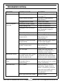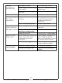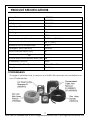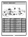
1
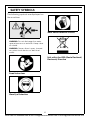
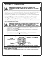
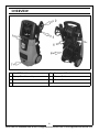
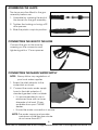
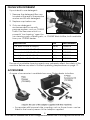
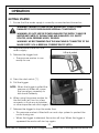
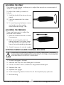
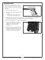
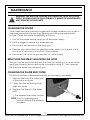
WARNING: Do not use the machine without reading this manual
POWER WASHER
MODEL NO: JET 9000
PART NO: 7333502
OPERATION & MAINTENANCE
INSTRUCTIONS
GC0913
INTRODUCTION
Thank you for purchasing this CLARKE Power Washer.
The machine has been designed to use hot or cold water to clean any
surfaces which can stand the force of the high pressure water jet and the
action of the detergents used.
The machine must only be used for the purpose for which it was designed.
Before attempting to use this product, please read this manual thoroughly and
follow the instructions carefully. In doing so you will ensure the safety of yourself
and that of others around you, and you can look forward to your purchase
giving you long and satisfactory service.
GUARANTEE
This product is guaranteed against faulty manufacture for a period of 12
months from the date of purchase. Please keep your receipt which will be
required as proof of purchase.
This guarantee is invalid if the product is found to have been abused or
tampered with in any way, or not used for the purpose for which it was
intended.
Faulty goods should be returned to their place of purchase, no product can
be returned to us without prior permission.
This guarantee does not effect your statutory rights.
2
Parts & Service: 020 8988 7400 / E-mail: [email protected] or [email protected]
GENERAL SAFETY RULES
WARNING: WATER AT HIGH PRESSURE CAN BE DANGEROUS AND CAN
CAUSE DAMAGE IF THE OPERATOR IS CARELESS. NEVER ALLOW ANYONE
TO OPERATE THIS MACHINE UNLESS THEY ARE FAMILIAR WITH THE SAFETY
PRECAUTIONS.
1. High pressure water jets can be dangerous if subject to misuse. They must
not be directed at animals or people.
2. NEVER allow children or untrained personnel to use this product.
3. NEVER operate the power washer with any covers removed.
4. NEVER attempt any electrical or mechanical repairs to this power washer.
Always refer to your Clarke dealer.
5. NEVER supply any liquid other than water to the water inlet.
6. Never use the detergent facility to introduce flammable liquids/solvents,
e.g. paint thinners, petrol, oil due to risk of explosion.
7. ALWAYS release any residual pressure in the machine by turning off the
water supply and operating the trigger, before disconnecting the hose.
8. ALWAYS keep the pressure washer itself dry and clear of water spray.
9. Never direct the spray jet at the pressure washer itself or any other
electrical equipment.
10. ALWAYS wear protective clothing, safety shoes and safety glasses. Loose
particles & other debris may be propelled at high speed by the water jet.
11. ALWAYS hold the spray gun firmly & expect the gun to ‘kick’ when starting.
12. ALWAYS disconnect from the water supply and ensure the machne is
completely drained when not in use. Store in a cool dry location.
13. Only use chemical cleaning agents (detergents), that are approved for
pressure washers. CLARKE Traffic Film Remover or CLARKE Wash and Wax
(available from your dealer), are recommended.
14. ALWAYS disconnect from the electrical power supply and remove the plug
from the socket before carrying out any maintenance.
15. ONLY use original spare parts from the Clarke service department.
16. High pressure hoses, fittings and couplings are important for the
safety of the machine. Use only hoses, fittings and co uplings
recom men de d by the manufacturer.
17. N EV ER use the pressure washer if the power cab l e o r other
important parts of th e p ower washe r a re damaged.
18.If an extension cable is used, the cable and plug must be of
watertight construction. Inadequate extension cables can be
dangerous.
3
Parts & Service: 020 8988 7400 / E-mail: [email protected] or [email protected]
SAFETY SYMBOLS
The following symbols are displayed on
the machine.
Wear Hand Protective Gloves
WARNING: Do not discharge the water
spray at persons or animals. Keep clear
of nozzle.
WARNING: Never direct spray toward
any electrical device or electrical
outlet.
Falls within the WEE (Waste Electrical/
Electronic) Directive
Read Instructions
Wear Eye Protection
4
Parts & Service: 020 8988 7400 / E-mail: [email protected] or [email protected]
ELECTRICAL CONNECTIONS
WARNING: READ THESE ELECTRICAL SAFETY INSTRUCTIONS
THOROUGHLY BEFORE CONNECTING THE PRODUCT TO THE MAINS
SUPPLY.
Before switching the product on, make sure that the voltage of your electricity supply is
the same as that indicated on the rating plate. This product is designed to operate on
230VAC 50Hz. Connecting it to any other power source may cause damage.
This product may be fitted with a non-rewireable plug. If it is necessary to change the
fuse in the plug, the fuse cover must be refitted. If the fuse cover becomes lost or
damaged, the plug must not be used until a suitable replacement is obtained.
If the plug has to be changed because it is not suitable for your socket, or due to
damage, it should be cut off and a replacement fitted, following the wiring instructions
shown below. The old plug must be disposed of safely, as insertion into a mains socket
could cause an electrical hazard.
WARNING: THE WIRES IN THE POWER CABLE OF THIS PRODUCT ARE
COLOURED IN ACCORDANCE WITH THE FOLLOWING CODE:
BLUE = NEUTRAL
BROWN = LIVE YELLOW AND GREEN = EARTH
• The wire which is coloured Blue must be connected to the terminal which is
marked N or coloured Black.
• The wire which is coloured Brown must be connected to the terminal which is
marked L or coloured Red.
• The wire which is coloured Yellow and Green must be connected to the
terminal which is marked E (
) or coloured Green.
Plug must be BS1363/A approved.
Always fit a 13 Amp fuse.
Earth
(Green and Yellow)
Live
Neutral
(Brown)
(Blue)
Ensure that the outer sheath of the cable is firmly held by the clamp
WE STRONGLY RECOMMEND THAT THIS MACHINE IS CONNECTED TO THE MAINS SUPPLY VIA A
RESIDUAL CURRENT DEVICE (RCD)
If in any doubt, consult a qualified electrician. DO NOT attempt any repairs yourself.
5
Parts & Service: 020 8988 7400 / E-mail: [email protected] or [email protected]
OVERVIEW
1
On/OFF Switch
5
Detergent Container
2
Spray Gun Assembly
6
Power Cable
3
Reel Handle
7
Mains Water Inlet
4
Lance
6
Parts & Service: 020 8988 7400 / E-mail: [email protected] or [email protected]
LIST OF CONTENTS
The following items should be supplied in the carton. If any parts are missing or
damaged, please see your Clarke dealer where you purchased the machine.
1 x Power Washer
1 x Gun Assembly
1 x Lance c/w fitted Pencil-Jet / Fan - High / Low Nozzle
1 x Hose Assembly on integral Hose-Reel
1 x Inlet Hose Adaptor
1 x Instruction Manual
1 x Accessory Adaptor
BEFORE USE
Unpack your power washer and check to ensure all the items listed above are
present.
UNFOLDING THE HOSE REEL HANDLE
1. Open the reel handle from its
folded position before use.
2. Release the hose from the
retaining clip on the hose reel,
then pull the hose from the reel to
unwind whatever length is
required.
• Winding the handle clockwise
will reduce the length of the
hose.
• If the spray gun/lance assembly is not attached, the hose can be
secured in the retaining clip when the hose is re-wound.
7
Parts & Service: 020 8988 7400 / E-mail: [email protected] or [email protected]
ASSEMBLING THE LANCE
The lance must be fitted to the gun
assembly before use.
1. Assemble by screwing the end of
the lance into the gun assembly.
2. Tighten the locking nut using a 22
mm spanner.
3. Slide the plastic cap into position.
CONNECTING THE GUN TO THE HOSE
Connect the gun to the hose by
screwing on the connector and
tightening with a 17 mm spanner.
CONNECTING THE MAINS WATER SUPPLY
NOTE: Always follow any regulations of
your local water supplier.
1. Screw the inlet adaptor to the
water inlet as shown.
2. Connect the mains water supply
hose to the inlet adaptor. A
standard garden hose is suitable.
• It is recommended to use a
reinforced hose with an inner
diameter of at least 10 mm
available from your CLARKE
dealer.
• Ensure the water connection is secure.
NOTE: The water source must provide
a minimum of 6.6 litres per minute
at not more than 40°C.
8
Parts & Service: 020 8988 7400 / E-mail: [email protected] or [email protected]
FILLING WITH DETERGENT
If you intend to use detergent:
1. Remove the detergent filler cap
located at the rear of the pressure
washer and fill with detergent.
2. Replace cap before use.
3. Only use detergents
recommended for use with
pressure washers, such as CLARKE
Traffic Film Remover which is a
powerful ‘low foaming’ agent for
car cleaning, patio cleaning etc., or CLARKE Wash & Wax, both available
from your CLARKE dealer.
DESCRIPTION
SIZE
PART NUMBER
Car Wash & Wax Shampoo
5 Litre
3050815
Concentrated Traffic Film Remover
5 Litre
3050821
Concentrated Traffic Film Remover
25 Litre
3050820
Ready To Use Traffic Film Remover
5 Litre
3050818
Ready To Use Traffic Film Remover
25 Litre
3050819
The use of unsuitable cleaning agents may adversely affect the safety of the
machine. Before use, refer to correct operating temperatures on page 17.
ACCESSORIES
A range of accessories is available from your Clarke dealer including:
• Accessories with bayonet style couplings such as those shown can be
fitted to the hose by means of the adaptor supplied.
9
Parts & Service: 020 8988 7400 / E-mail: [email protected] or [email protected]
OPERATION
GETTING STARTED
1. Ensure that the water supply is correctly connected and turned on.
WARNING: FAILURE TO TURN ON THE WATER FULLY COULD CAUSE
DAMAGE TO THE POWER WASHER INTERNAL COMPONENTS.
WARNING: DO NOT USE THE POWER WASHER IF THE SUPPLY CABLE OR
IMPORTANT PARTS OF THE MACHINE ARE DAMAGED, E.G. SAFETY
DEVICES, HIGH PRESSURE HOSES, TRIGGER.
WARNING: WE RECOMMEND THAT THIS MACHINE IS CONNECTED TO THE
MAINS SUPPLY VIA A RESIDUAL CURRENT DEVICE (RCD).
2. Plug the power cable into the
mains supply.
3. Release the trigger lock.
• The pressure washer is now
ready for use.
4. Press the start switch (‘I’).
5. Pull the trigger.
NOTE: When the trigger is pulled the
pressure of water will cause
the lance/gun assembly to
kick back suddenly.
6. When using the power washer for
the first time, let it run for a few
moments so that any air bubbles
or other impurities are discharged.
7. Release the trigger to stop the water flow.
• This pressure washer is fitted with an auto stop system to protect the
motor during use.
• When the trigger is released, the motor will stop. When the trigger is
squeezed the motor will start up again.
10
Parts & Service: 020 8988 7400 / E-mail: [email protected] or [email protected]
ADJUSTING THE SPRAY
The nozzle is adjustable to allow you to adjust the spray from a narrow jet of
water to a wide spray.
To adjust the nozzle, proceed as
follows:
1. Hold the shaft of the lance in one
hand.
2. Twist the nozzle with the other
hand.
3. To vary the spray between narrow
and wide, turn the nozzle
anticlockwise through 180o.
ADJUSTING THE PRESSURE
There are three ways to adjust the
pressure of the water:
1. Slide the nozzle forwards to lower
the pressure.
2. Back away from the surface
being cleaned. The further away
you are the less the pressure will
be on the surface being cleaned.
3. Adjust the spray to a wider angle.
APPLYING CHEMICALS AND CLEANING SOLVENTS
CAUTION: IF YOUR EYES COME INTO CONTACT WITH ANY CLEANING
FLUIDS, RINSE THEM IMMEDIATELY WITH PLENTY OF FRESH, CLEAN WATER
AND SEEK MEDICAL ADVICE IF REQUIRED.
1. Ensure the trigger is locked.
2. Remove the cap from the detergent container.
3. Fill the container with a suitable bio-degradable detergent.
4. Replace the cap.
5. Squeeze the trigger.
6. Pull the adjusting sleeve forward to set the required spray pressure.
7. Start washing.
11
Parts & Service: 020 8988 7400 / E-mail: [email protected] or [email protected]
SHUTTING DOWN
When you have finished using the
power washer, follow the procedure
below to switch off and disconnect
the unit:
1. Press the stop switch (‘O’).
2. Turn the mains water supply off at
the tap.
• NEVER turn the water off with
the power washer running.
3. Release the pressure in the pump and hose by squeezing the trigger for a
few seconds until no more water comes out of the nozzle.
4. Move the trigger lock to the locked position.
5. Disconnect the mains power
supply and store the cable in its
position on the rear of the
machine.
6. Wind the hose onto the reel and
store the spray gun/lance in the
holder on the front of the power
washer as shown on page 6.
12
Parts & Service: 020 8988 7400 / E-mail: [email protected] or [email protected]
MAINTENANCE
WARNING: THE MACHINE SHALL BE DISCONNECTED FROM THE POWER
SUPPLY BY REMOVING THE PLUG DURING CLEANING OR MAINTENANCE
AND WHEN REPLACING PARTS.
CLEANING THE NOZZLE
If the nozzle becomes partially clogged with foreign material such as dirt or
limescale, excessive pressure may develop and the pump pressure will
pulsate. Clean the nozzle immediately as follows:
1. Turn off the power washer and turn off the water supply.
2. Pull the trigger to relieve any water pressure.
3. Disconnect the lance from the spray gun.
4. Remove any obstructions by directing water supply into the end of the
lance for 30 seconds to back flush loose particles.
5. Reconnect the lance to gun and turn on water supply.
REMOVING THE SPRAY GUN FROM THE HOSE
The gun can be disconnected from the hose for cleaning or to unblock the
spray gun/hose by disconnecting the connection using a 17 mm spanner.
Pull the hose away from the spray gun.
CLEANING THE WATER INLET FILTER
This filter should be checked periodically and cleaned if necessary.
1. Remove filter from the water inlet
of the pump as shown.
2. Clean the filter by flushing both
sides with water.
3. Replace the filter into the water
inlet.
• The tapered side faces inwards.
NOTE: Do not operate power
washer without filter properly
installed.
13
Parts & Service: 020 8988 7400 / E-mail: [email protected] or [email protected]
SERVICING
All repairs and maintenance operations must be carried out by technically
qualified personnel while disconnected from the power and water supplies.
Correct use and maintenance is necessary to guarantee the power washer's
reliability and best performance.
Please only use the correct spare parts as supplied by your Clarke dealer.
ANNUALLY
LIMESCALE
Periodically the pump should be checked for limescale buildup, dependant
upon the hardness of the local water supply.
Please contact the CLARKE International Service Dept.
DE-COMMISSIONING THE PRODUCT
Should the product become completely unserviceable and
require disposal, dispose of the product according to local
regulations. Recycle unwanted materials instead of disposing of
them as waste. All tools, accessories and packaging should be
sorted, taken to a recycling centre and disposed of in a manner
which is compatible with the environment.
STORING THE POWER WASHER
1. Disconnect the high pressure hose and drain all water from the hose.
2. Make sure that the power washer has been thoroughly cleaned before
storing it in a clean dry place.
3. Avoid storing the power washer at freezing temperatures.
14
Parts & Service: 020 8988 7400 / E-mail: [email protected] or [email protected]
TROUBLESHOOTING
PROBLEM
POSSIBLE CAUSE
No water delivery. Water filter blocked.
SOLUTION
See cleaning the water filter
on page 13.
Pump valves jammed.
Contact Clarke Service
Department.
Clogged lance nozzle.
Clean the nozzle.
Insufficient water supply.
Check connections.
Pump taking in air.
Check connections.
Detergent inlet sucking in
air.
Check connections and
that detergent supply is
topped up.
Water filter dirty.
Clean or replace.
Worn out gaskets or valve
components.
Contact Clarke Service
Department for
replacement.
Exceeding the inlet water
temperature.
Make sure the water supply
is below 60 degrees.
Damaged or warn out
nozzle components.
Contact Clarke Service
Department for
replacement.
Low Voltage.
Make sure the pressure
washer is connected to a
suitable power supply.
Machine is noisy.
Air intake worn out / dirty/
blocked valves. Excess
water temperature.
Check air inlet. Contact
Clarke Service Department.
Reduce water temperature.
Motor suddenly
stops.
Thermal protection has
activated due to
overheating.
Switch off the machine and
wait until the unit has cooled
down sufficiently.
Pressure drop.
Air in system.
Bleed system by quickly
operating trigger several
times. If necessary operate
the machine briefly without
the high pressure hose
connected.
Worn high pressure nozzle.
Renew nozzle.
Low or irregular
pressure
15
Parts & Service: 020 8988 7400 / E-mail: [email protected] or [email protected]
Pressure
fluctuations or
pressure drop.
Shortage of water.
Turn water tap on fully.
Water supply hose too long/ Use a 1/2” diameter water
too narrow.
supply hose.
No water due to clogged
inlet filter.
Clean water inlet filter.
Oil leak.
Worn seals.
Contact your Clarke dealer.
Motor does not
start when
switched on.
Plug is not connected
properly.
Check plug and lead and
have them replaced by a
qualified electrician if
necessary.
Mains fuse tripped/blown.
Renew fuse or reset.
Motor hums when Mains voltage too low.
trigger operated
and does not start. Incorrect diameter cable
resulting in voltage drop.
Motor cuts out trigger open.
Additives are not
being supplied.
Have electrical connection
checked.
Use correct diameter cable.
Pump seals stuck.
Contact your Clarke dealer.
Motor protection switch has
been activated due to
overheating or motor
overload.
Ensure supply voltage and
unit voltage are equal.
Switch off and allow to cool
for at least three minutes.
Nozzle partly clogged.
Clean using the supplied
nozzle cleaning needle.
Additive container empty.
Fill additive container.
Lance not correctly set.
Put lance on low pressure
setting.
16
Parts & Service: 020 8988 7400 / E-mail: [email protected] or [email protected]
PRODUCT SPECIFICATIONS
Model Number
JET 9000
Part Number
7333502
Voltage
230V/50Hz
Motor Input Power
2600 W
Duty Cycle
Continuous
Working pressure
123 bar
Maximum pump output pressure
200 bar
Maximum output flow rate
7.75 l/min (465 l/hr)
Maximum output temperature
400C (1040F)
Maximum input temperature
0-400C
Detergent tank capacity
2200 ml
Sound Pressure Level (LWA)
81
Sound power level (LWA)
94
Guaranteed sound power level (LWA) 98
Uncertainty Factor K
3.44
Dimensions (L x W x H)
305 x 328 x 806 mm
Weight
23.65 kg
CONSUMABLES
A range of suitable hose, shampoo and traffic film remover are available from
your Clarke dealer.
17
Parts & Service: 020 8988 7400 / E-mail: [email protected] or [email protected]
PARTS LIST - FRAME & BODY
POS DESCRIPTION
CODE
POS DESCRIPTION
CODE
TMC9000FB17
1
Self-tapping Screw
TMC9000FB01
17
Pump Assembly
2
Handle Pin
TMC9000FB02
18
Front Cover
TMC9000FB18
3
Hose Reel
TMC9000FB03
19
Handle
TMC9000FB19
4
Self-tapping Screw
TMC9000FB04
20
Cable Sleeve
TMC9000FB20
5
Cable Hook
TMC9000FB05
21
Switch Holder
TMC9000FB21
6
Cap Screw
TMC9000FB06
22
Switch Panel
TMC9000FB22
7
Spring Gasket
TMC9000FB07
23
Power Switch
TMC9000FB23
TMC9000FB24
8
Flat Gasket
TMC9000FB08
24
Air Outlet
9
Base
TMC9000FB09
25
Self-tapping Screw
TMC9000FB25
10
Container Cap
TMC9000FB10
26
Cable Retainer
TMC9000FB26
11
Container
TMC9000FB11
27
Cable Gland
TMC9000FB27
12
Container Retainer
TMC9000FB12
28
Board Clip
TMC9000FB28
13
Capacitor Clamp
TMC9000FB13
29
Spring Clip
TMC9000FB29
14
Wheel
TMC9000FB14
30
Insulation Sleeve
TMC9000FB30
15
Wheel Retainer
TMC9000FB15
31
Power Cable
TMC9000FB31
16
Wheel Cover
TMC9000FB16
32
Spray Gun & Lance
TMC9000FB32
18
Parts & Service: 020 8988 7400 / E-mail: [email protected] or [email protected]
PARTS LIST - INTERNAL COMPONENTS
19
Parts & Service: 020 8988 7400 / E-mail: [email protected] or [email protected]
PARTS LIST - INTERNAL COMPONENTS
POS DESCRIPTION
CODE
POS
DESCRIPTION
CODE
1
Motor Winding Cover
TMC900001
27
Relief Valve
TMC900027
2
Motor Fan
TMC900002
27-1
Sealing Ring
TMC9000271
3
Induction Motor
TMC900003
27-2
Relief Valve Piston
TMC9000272
4
Terminal Box
TMC900004
27-3
Sealing Ring
TMC9000273
5
Capacitor/wire
TMC900005
27-4
Relief Valve Support
TMC9000274
5-1
Capacitor/wire
TMC9000051 27-5
Relief Valve Spring
TMC9000275
5-2
Insulation Sleeve
TMC9000052 27-6
Sealing Ring
TMC9000276
5-3
Clip
TMC9000053 27-7
Valve Seat Cover
TMC9000277
6
Main Switch Wire
TMC900006
Valve Connect Screw TMC9000278
6-1
Main Switch Wire
TMC9000061 27-9
6-2
Insert Spring
TMC9000062 27-10 Auto Stop Spring
6-3
Earth Terminal
TMC9000063 27-11 Spring Press
TMC90002711
7
Washer
TMC900007
TMC90002712
27-8
Safety Valve Stem
27-12 Sealing Ring
TMC9000279
TMC90002710
8
Spring Washer
TMC900008
27-13 Relief Valve Bonnet
TMC90002713
9
Self tapping Screw
TMC900009
27-14 Switch Box
TMC90002714
10
Termianl Box Cap
TMC900010
27-15 Contact Point
TMC90002715
11
Cam
TMC900011
27-16 Micro Switch
TMC90002716
12
Spring Washer
TMC900012
27-17 Micro Switch Wire
TMC90002717
13
Hex Screw
TMC900013
27-18 Insert Spring
TMC90002718
14
Washer
TMC900014
27-19 Insulation Sleeve
TMC90002719
15
Needle Bearing
TMC900015
27-20 Switch Box Cover
TMC90002720
16
Bearing Washer
TMC900016
27-21 Self Tapping Screw
TMC90002721
17
Spring Seat
TMC900017
27-22 Sealing Ring
TMC90002722
18
Plunger
TMC900018
27-23 Relief Valve Bonnet
TMC90002723
19
Plunger Spring
TMC900019
28
Valve Body
TMC900028
20
Seal Ring
TMC900020
29
Oil Seal
TMC900029
21
Seal Ring
TMC900021
30
Guide
TMC900030
22
Inlet Connector
TMC900022
31
Water Seal
TMC900031
23
Inlet Connector Seal
TMC900023
32
Spring Washer
TMC900032
24
Filter Core
TMC900024
33
Hex Screw
TMC900033
25
Inlet Hose
TMC900025
42
Main Valve
TMC900042
26
Sealing Ring
TMC900026
42-1
Main Valve Cover
TMC9000421
20
Parts & Service: 020 8988 7400 / E-mail: [email protected] or [email protected]
34
Hex Screw Insert
TMC900034
42-2
Main Valve Seat
TMC9000422
35
Pump
TMC900035
43
Hose
TMC900043
36
Spring Washer
TMC900036
44
Nozzle
TMC900044
37
Hex Screw
TMC900037
45
Outlet Connector
TMC900045
38
Hex Screw
TMC900038
46
Hex Screw Insert
TMC900046
39
Sealing Ring
TMC900039
47
Spring
TMC900047
40
One-way Valve
TMC900040
48
Steel Ball
TMC900048
40-1
One-way Valve Cover
TMC9000401 49
Sealing Ring
TMC900049
40-2
One-way Valve Core
TMC9000402 50
Sealing Ring
TMC900050
40-3
One-way Valve Spring
TMC9000403 51
Suction Connector
TMC900051
Sealing Ring
TMC900052
40-4
One-way Valve Seat
TMC9000404 52
41
One-way Valve Insert
TMC900041
21
Parts & Service: 020 8988 7400 / E-mail: [email protected] or [email protected]
HOSE REEL ASSEMBLY
No DESCRIPTION
CODE
1
Screw
TMC9000HOSE01 8
No DESCRIPTION
Seal Ring
TMC9000HOSE08
CODE
2
Crank Handle TMC9000HOSE02 9
Seal Ring
TMC9000HOSE09
3
Bolt
TMC9000HOSE03 10
Hose Spool (L/H) TMC9000HOSE10
4
Crank Handle TMC9000HOSE04 11
Hub
Support Bracket TMC9000HOSE11
5
Support
Bracket
TMC9000HOSE05 12
HP Hose
Connector
TMC9000HOSE12
6
Hose Spool
(right)
TMC9000HOSE06 13
Retaining Clip
TMC9000HOSE13
7
High Pressure
Hose
TMC9000HOSE07 14
Cover Plug
TMC9000HOSE14
No DESCRIPTION
CODE
No DESCRIPTION
CODE
1
Lance Assy
TMCFQ301
3
TMC9000ADAPTOR
2
Gun Assembly
TMCFQ302
Adaptor
22
Parts & Service: 020 8988 7400 / E-mail: [email protected] or [email protected]
DECLARATION OF CONFORMITY
23
Parts & Service: 020 8988 7400 / E-mail: [email protected] or [email protected]