1
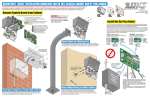
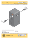
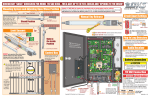
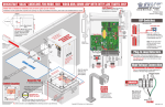
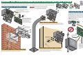
QUICKSTART “BASIC” INSTALLATION GUIDELINES FOR AN 1812 ACCESS PLUS CABINET AND BY-PASS BOARD
It is highly recommended that you consult the Installation/Owner’s manual for complete instructions on all the different types of installations. The 1812 Access Plus
Telephone Entry System involves the installation of the 1812 cabinet, the by-pass board for the incoming telephone line, and wiring of these components (On reverse side).
Be sure that all dirt, metal or wood debris is removed from inside cabinet after mounting it. This could damage the control board and cause a malfunction during operation.
1
4
7
2
5
8
0
1
3
4
6
7
9
2
5
8
0
1
3
4
6
7
9
4
The control board removal is the same for all models.
J4
1
2
3
4
5
6
7
8
BA
D
DNJ1
S
RS
-48
RX
5
LA
DO N
RJ WN
-4
Ja 5
(Catck
5)
SW
1
MO
DE
19
OV
KE
M
CO
DE
72
-01
0
Surface
Mount
Cabinet
Surface
Mount Curved
Cabinet
19
18-Pin Main
Terminal
Connector
12
70
34
-01
J2 0
56
78
SP
EA
KE
VO R
L
J1
J4
1
2
3
4
5
6
7
8
BA
D
DNJ1
S
RS
-48
RX 5
LA
DO N
RJ-WN
Ja 45
(Catck
5)
SW
1
ON
1
2
3
4
5
6
7
8
9
10
11
12
13
14
15
16
17
18
MO
DE
M
CO
DE
197
2-0
10
OV
KE
YP
AD
MI
C VO
L
197
0-0
10
12
J2
34
56
78
91
Remove the 18-pin main terminal
connector, and if necessary, the 8-pin
RS-485 connector from the control
board by gently pulling them straight
up. This will make wiring to the
control board easier. Note the
orientation and numbering sequence
of each connector to correctly wire it.
0 11
6
9
120 Glasgow Avenue
Inglewood, California 90301
3
5
6
8
9
Wall
Mount
Cabinet
U.S.A.
Flush
Mount
Cabinet
“Entry” switch position:
“By-Pass” switch position:
Routes incoming phone line through 1812
Access Plus and then to the home phone.
Routes incoming phone line directly to the
home phone, bypassing 1812 Access Plus.
ENTRY BY-PASS
ENTRY BY-PASS
SW1
SW1
1875-010
Mount Cabinet on a Mounting Post
1875-010
EARTH
GND
EARTH
GND
1
2
3
CENTRAL
OFFICE
Use existing 4 holes in cabinet box to bolt the surface or wall mount models on a DoorKing
mounting post (there are several different styles available). Use the hardware that is supplied with
the mounting post. Run all necessary wires through the post to the cabinet (See reverse side).
SP
EA
KE
VO R
L
3
The 1812 Access Plus by-pass board provides a method to by-pass the 1812 Access Plus and route the
incoming telephone line directly to the homeowner’s phone. It must be installed as part of the 1812
Access Plus system. All telephone wires for the 1812 Access Plus must pass through the by-pass board.
Mount the by-pass board in a location that is easily accessible by the homeowner. In case of 1812 Access
Plus trouble or maintenance, the homeowner will use the by-pass switch on the board to route the
incoming telephone line directly to their home phone. If the by-pass board is installed outdoors, it must be
installed in a NEMA Type 4 enclosure (not supplied) with conduit to protect the board and wires from
direct exposure to landscape sprinklers, rain, snow, and other elements.
8-Pin
RS-485
Connector
91
0 11
8
Install the By-Pass Board
YP
AD
MI
C VO
L
2
0
1. Unlock and open the 1812 Access Plus door.
2. Disconnect the keypad plug and door accessories
plug from the control board.
3. Remove the 4 screws. Carefully remove control board.
CAUTION Keep the control board in a protected area
during the installation.
J1
ON
1
2
3
4
5
6
7
8
9
10
11
12
13
14
15
16
17
18
7
IMPORTANT The 1812 Access Plus and by-pass board
MUST be properly grounded! A gooseneck mounting post
anchored in concrete does not make a good ground.
5
0
1
Remove Control Board from Cabinet
2
4
PHONE
IN
5
6
PHONE
OUT
7
8
1
2
3
CENTRAL
OFFICE
HOME
Home Phone
Incoming
Phone Line
4
PHONE
IN
5
6
PHONE
OUT
7
8
HOME
Home Phone
Incoming
Phone Line
4
7
5
6
8
9
4
7
5
6
8
9
0
0
Bolt flush mount box
into the rough-in box
with 4 supplied bolts.
EN
sh
Flu nt
u
Mo
x
o
B
TR
Y
1
EA
R
GNTH
D
7
0
4
8
5
9
2
-PA
3
6
SS
4
1
Ground by-pass board.
Minimum 12 AWG wire
(Not supplied).
Ro
u
gh
-In
CE 2
N
OF TRAL
FIC
E
Plastic screw anchors for
masonry if required.
(Not supplied)
Bo
x
If installed
outdoors.
NE
M
en A Ty
clo pe
s
4
ou ure f
t
o
ins doo r
tal r
(No la
t S tio
up
plie n.
d)
(Sh Con
ow du
n in it
sid
ew
all)
Co
n
(Sh duit
ow
n in
sid
ew
all)
Mount Cabinet Directly to a Wall or Pilaster
Flush Mount Cabinet in a Pilaster, Wall or Kiosk
Mount rough-in box into the pilaster, wall or kiosk. Run conduit inside wall into bottom of rough-in
box if desired. Use appropriate hardware (Not supplied) to secure the rough-in box in place. Run all
necessary wires through the conduit in to the rough-in box (See reverse side).
Use the 4 existing holes in the cabinet box to screw the surface or wall mount models to
the wall. Run conduit inside or outside of wall or pilaster if desired. Use appropriate
hardware to mount the cabinet (Not supplied). Be sure that the mounting hardware does
not protrude into the cabinet where it could cause a short. Run all necessary wires through
the conduit to the cabinet (See reverse side).
Dedicated
Telephone
Wire Conduit
From
Incoming
Telephone
Line
3
ON4
IN E
PH
BY
5
SW
1
6
7
187
5
PH 6
O
OUNE
T
7
HO
From
1812’s
18-Pin
Main
Terminal
5-08
10
8
ME
From
Home
Phone
Use only twisted pair telephone wire that is rated for direct
underground burial (Cat5e Gel Filled (flooded) UV resistant
direct burial cable in conduit is recommended).
DO NOT use wire that is rated for indoor application use.
DO NOT run telephone wires in the same conduit as high
voltage AC wire.
It is recommended to run all necessary wires to the by-pass
board (See reverse side) in a “dedicated” telephone wire
conduit.
QUICKSTART “BASIC” WIRING GUIDELINES FOR AN 1812 ACCESS PLUS SYSTEM WITH ACCESS CONTROL DEVICE(S)
It is highly recommended that you consult the Installation/Owner’s manual for complete wiring instructions on all the different types of installations, programming and internet connections.
Basic Programming for the 1812 Access Plus
1875-010
1
2nd Line
Yellow
Older
Residential
Homes
(-) Ring
Orange Pair
(+) Tip
3rd Line (-) Ring
Phone Wiring
Basics “101”
Phone at
Home #12
Cat5e
Ring
Phone at
Home #13
TIP (+):
White/blue mark
RING (-):
Blue/white mark
Tip
Ring
Green Pair
Modern
Residential
Homes
(+) Tip
4th Line (-) Ring
8
HOME
Cat5e
24 AWG
800 ft
22 AWG
1600 ft
20 AWG
2200 ft
18 AWG
3600 ft
RING
TIP
Older Lines
Green Wire (+)
1. Press * 0 3 and enter the MASTER CODE. [* 0 3 _ _ _ _ (beep)]
2. Enter “1” for relay 1 or “2” for relay 2, then press *. [ _ *(beep)]
IMPORTANT All boards
MUST be properly
grounded or the system
will NOT function correctly!
AMPS
MAX
PHAS
GATE
DoorK
LOAD
E
60
ing,
Hz
Inc.,
Inglew
ood,
CA
4. Repeat steps 2 and 3 to set the other relay strike time if necessary.
Electric
Strike
k
loc
g
Ma
Without
Surge
Board
DO NOT power the 1812 Access Plus from
a 24-Volt source (Such as a gate operator).
Damage will occur to the 1812 Access
Plus that is NOT covered under DoorKing’s
warranty.
“Normally Close” Pedestrian Gate/Door with Maglock
(Terminal 15 and 16)
“Normally Open” Pedestrian Gate/Door with Electric Strike
(Terminal 14 and 16)
Magnetic locks or electric strikes must be powered from a
separate UL Listed power transformer. DO NOT power electric
strikes or magnetic locks from the 1812 Access Plus power
transformer. keep power wire runs as short as possible.
Ground
CAUTION
Power Transformer and Access Control Device(s)
Wire Run Table
Wire Size
Max Distance
18 AWG
100 ft
16 AWG
OV
200 ft
Over Voltage Power Note: LED located on
bottom left corner of board will light up if
too much power is applied to circuit board.
5
8
3
6
9
Daisy Chain
Wiring
t
tpu
Ou VAC
.5
16 VA
20
Supplied Power
Transformer
Program MASTER CODE
Phone In
1 RS-485 DATA A (+)
RS-485 RX
2 RS-485 DATA B (-)
RS-485 RX
3 RS-485 Common
LAN DOWN
BAD DNS
LAN
DOWN
4
MODEM/ TCP ENB
BAD
MODEM / TCP ENB
SW1
DNS
Switch Turned ON
5
LAN
6 CONNECTION
DATA TRANSMIT
PHONE LINE
IN USE
J1
J1
7
PHONE LINE
IN USE
8
Connector
(Cat5)
RS 485
Terminal
1972-010
(1-2)
2 TIP
3 GND
4 TIP Phone Out
(4-5)
5 RING
6
7
8
9
10
11 N.O.
12 N.C. Relay 1 Note: Each relay can control a
13 Com (11-13) normally open OR normally close
access control device. Relay
14 N.O.
Relay 2 contacts are rated for 3 amps @
15 N.C.
(14-16) 30 VAC maximum.
16 Com
17 16.5 Power
18 VAC (17-18)
Green Pair
5. Press “0 #” TOGETHER to end. [0 # (beeeeeep)]
Separate UL
Listed Power
Transformer
J1Terminal
1 RING
Ground 12 AWG Min.
Recommended
CONF
ORMS
ANSI/
UL-32TO
CAN/CCERT
5
SA IFIED
VEHI C22.2 TO
CULA NO.
53382
CLAS
247
R
S
GATE
MODE
OPER
L
ATOR
SERIA
HP
L
VOLTS
“Normally Open”
Vehicular
Gate Operator
(Terminal 11 and 13)
2
0
Master Code LED Description
J4
Main
Orange Pair
Recommended
tions.
7
ON
NG
instruc
4
Phone
Jack
Cat5e
Ground
3. Enter a two-digit strike time (00-99), then press *. [ _ _ *(beep)]
Note: Strike time entered in seconds. 00 = ¼ sec., 10 = 10 seconds, etc.
NI
1
Phone
Jack
Control Board
Programming Relay 1 and 2 Strike Time - (Factory default is 1 second)
WAR
Separate UL Listed power transformer if needed.
6 Devices
Maximum
Access Control Devices
gate.
is
ctions.
n to
in
pathnot stand
sight
play
while
in
in
gate
Read
gate gate
area
is path
owner
movin
or
’s
manua g. walk
throug
l and
h
safety
RS 485 Remote Device(s)
See Installation/Owner’s manual to configure the RS 485
access control device(s) (device address, termination
switch, programming etc). DO NOT power RS 485 device(s)
from the 1812 Access Plus power transformer.
Older Lines
Red Wire (-)
“Existing” Alarm System
MOV
SER ING
IOUS GAT
Operat
INJUE CAN
and e
free gate
RY CAU
of only
Do
OR
people when
or not allow
DEASE
and gate
operat
obstruarea
TH
e childre
Do
This “Quickstart” guideline is designed for installing a single 1812
Access Plus in a typical single family home application using the
factory default settings programmed in the 1812 Access Plus.
Complete installation instructions and programming manual is
available on the enclosed CD AND from our tech support web site.
CLICK HERE TO VISIT DOORKING’S TECHNICAL WEB SITE:
www.dkaccess.com/english/Telephone_Entry/telephone_entry.html.
Homeowner’s Phone(s)
Cat5e
U.S.A.
Complete Instructions
DO NOT run telephone wires in the same conduit as high voltage AC wire.
Green
Pair
Cat5e
Ground
120 Glasgow Avenue
Inglewood, California 90301
Check for polarity on the incoming telephone line to each board and maintain polarity
throughout the telephone line (TIP (+), RING (-).
Cat5e Without Surge Board
To “Existing”
Alarm Control Panel
Max Distance
Check Polarity of Telephone Line
TIP
RING
RING
TIP
TIP
Orange
Pair
Brown Pair
RJ31x
Phone Jack
installed
Before 1812
System
Locate Homeowner’s
Phone Line Inside Device
7
Wire Size
Cat5e Gel Filled (flooded) UV resistant direct burial cable run in conduit recommended.
Ring
Tip
6
PHONE
OUT
Cat5 Wire
(+) Tip Blue Pair
Black
5
Ring (-)
Ground 12 AWG Min.
1st Line
4
PHONE
IN
RING
Tip (+)
Red
3
TIP RING
RING
RING GND GND
2
CENTRAL
OFFICE
PHONE LINE
INPUT
OUTPUT
Cat5e
Phone at
Home #11
Central Office (C.O.)
Demarcation Device
Tip
SW1
EARTH
GND
TIP
Wire
Conversion
Green
ENTRY BY-PASS
1877-010
Ground 12 AWG Min.
Within 3 ft of Board
Use common electrical safety practices when connecting
telephone wires. You can receive a substantial jolt if the
phone rings while handling these wires.“RING” terminal
voltage varies and can be between -48 to -130 Volts AC,
depending on the distance to the central office.“TIP”
terminal is always positive with respect to RING terminal.
Four Conductor
Wire
The By-Pass board is required.
Optional P/N 1877-010
Recommended
Telephone Company
Demarcation Point
By-Pass Board
Phone Line Surge Suppressor
TIP
The 1812 has been programmed at the factory with many of the programming parameters (default setting) set for a typical
residential application with a single 1812 Access Plus.
However, you must program a “Master Code” before putting the 1812 Access Plus into service. If you
are using more than a single 1812 Access Plus in the system, or if you are using any of the advanced features of the 1812
Access Plus , such as Time Zones, Do-Not-Disturb Schedules, Call Forwarding, Holiday Schedules, Hold Open Schedules,
Directory Code Dial-Out Phone Numbers, Temporary Access Codes, etc., you will need to download the complete
Installation/Owner’s and Programming Manual from our tech support web site.
Telephone and RS 485 Wire Run (Cat5e) Table
MASTER
CODE
Blinking LED - Power is applied to the 1812
Access Plus and the processor is working
(Normal Mode).
LED ON Continuously - After master code push
button has been pressed, system will be in
Master Code programming mode. (Will revert
back to blinking LED if master code is not entered
within 10-seconds).
Push Button to Program “Master Code”
1. Press the Master Code push button.
(the LED will stay on continuously).
J3
Cat5 Cable
MIC VOL
KEYPAD
1970-010
SPEAKER
VOL
J2
OV
1 2 3 4 5 6 7 8 910 11
Polarity does not matter.
2. Enter a four digit Master Code number
then press “ ”, “beep” will be heard.
*
[ _ _ _ _ (beep)] (Write down master code).
To LAN/Router/Gateway
See Installation/Owner’s manual for
different connections to the internet.
MODEM/TCP switch must be ON.
Programming Simple Access Codes
Ground 12 AWG Min.
Within 3 ft of Board
Programming Simple Access Code(s) to Operate Relay 1 and/or 2 on a 24/7 Basis - (Maximum of 50 codes)
Ground
OUT OUT
GND GND
IN
OUTPUT
INPUT
LOW VOLTAGE LINE
IN
Low Voltage
Surge Suppressor
Optional P/N 1878-010
1. Press * 0 2 and enter the MASTER CODE. [* 0 2 _ _ _ _ (beep)]
2. Press 1 for relay 1 OR Press 2 for relay 2, then press . [ _ (beep)]
*
*
3. Choose and enter a five-digit simple access code, then press *. [ _ _ _ _ _ *(beep)]
4. Repeat steps 2 and 3 to enter additional simple access codes.
1878-010
Copyright 2011 DoorKing, Inc. All rights reserved.
5. Press “0 #” TOGETHER to end. [0 # (beeeeeep)]
1812-168-D-12-11