1
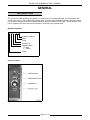
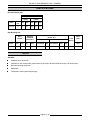
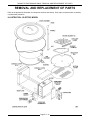
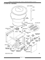
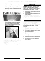
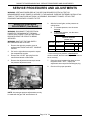
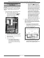
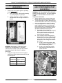
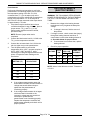
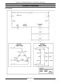
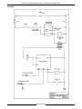
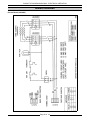
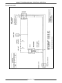
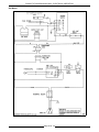
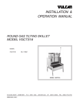
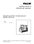
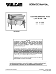
SERVICE MANUAL
ROUND COUNTER TOP
TILTING BRAISING PANS
(16 GALLON)
GAS AND ELECTRIC
VGCTS16
ML-114827
VECTS16
ML-114825
VGCTS16 SHOWN ON STAND
- NOTICE This Manual is prepared for the use of trained Vulcan Service
Technicians and should not be used by those not properly
qualified. If you have attended a Vulcan Service School for this
product, you may be qualified to perform all the procedures
described in this manual.
This manual is not intended to be all encompassing. If you have
not attended a Vulcan Service School for this product, you should
read, in its entirety, the repair procedure you wish to perform to
determine if you have the necessary tools, instruments and skills
required to perform the procedure. Procedures for which you do
not have the necessary tools, instruments and skills should be
performed by a trained Vulcan Service Technician.
Reproduction or other use of this Manual, without the express
written consent of Vulcan, is prohibited.
A product of VULCAN-HART
Form 24643 (MARCH 1999)
LOUISVILLE, KY 40201-0696
ROUND TILTING BRAISING PANS
TABLE OF CONTENTS
GENERAL . . . . . . . . . . . . . . . . . . . . . . . . . . . . . . . . . . . . . . . . . . . . . . . . . . . . . . . . . . . . . . . . . . . . . . . . . . . . .
Introduction . . . . . . . . . . . . . . . . . . . . . . . . . . . . . . . . . . . . . . . . . . . . . . . . . . . . . . . . . . . . . . . . . . . . . . . .
Model Designations . . . . . . . . . . . . . . . . . . . . . . . . . . . . . . . . . . . . . . . . . . . . . . . . . . . . . . . . . . . . . .
Control Location . . . . . . . . . . . . . . . . . . . . . . . . . . . . . . . . . . . . . . . . . . . . . . . . . . . . . . . . . . . . . . . . .
Specifications . . . . . . . . . . . . . . . . . . . . . . . . . . . . . . . . . . . . . . . . . . . . . . . . . . . . . . . . . . . . . . . . . . . . . .
Electric Braising Pan . . . . . . . . . . . . . . . . . . . . . . . . . . . . . . . . . . . . . . . . . . . . . . . . . . . . . . . . . . . . .
Gas Braising Pan . . . . . . . . . . . . . . . . . . . . . . . . . . . . . . . . . . . . . . . . . . . . . . . . . . . . . . . . . . . . . . . .
Tools . . . . . . . . . . . . . . . . . . . . . . . . . . . . . . . . . . . . . . . . . . . . . . . . . . . . . . . . . . . . . . . . . . . . . . . . . . . . .
3
3
3
3
4
4
4
4
REMOVAL AND REPLACEMENT OF PARTS . . . . . . . . . . . . . . . . . . . . . . . . . . . . . . . . . . . . . . . . . . . . . . . . . 5
Illustration - Electric Model . . . . . . . . . . . . . . . . . . . . . . . . . . . . . . . . . . . . . . . . . . . . . . . . . . . . . . . . . . . . . 5
Illustration - Gas Model . . . . . . . . . . . . . . . . . . . . . . . . . . . . . . . . . . . . . . . . . . . . . . . . . . . . . . . . . . . . . . . 6
Thermostats (Electric Model) . . . . . . . . . . . . . . . . . . . . . . . . . . . . . . . . . . . . . . . . . . . . . . . . . . . . . . . . . . . 7
Right and Left Console Cover . . . . . . . . . . . . . . . . . . . . . . . . . . . . . . . . . . . . . . . . . . . . . . . . . . . . . . . . . . 8
Bottom Cover . . . . . . . . . . . . . . . . . . . . . . . . . . . . . . . . . . . . . . . . . . . . . . . . . . . . . . . . . . . . . . . . . . . . . . 8
Temperature Controller and Potentiometer
(Gas Model) . . . . . . . . . . . . . . . . . . . . . . . . . . . . . . . . . . . . . . . . . . . . . . . . . . . . . . . . . . . . . . . . . . . . 8
Hi Limit Thermostat (Gas Model) . . . . . . . . . . . . . . . . . . . . . . . . . . . . . . . . . . . . . . . . . . . . . . . . . . . . . . . . 8
Heater Contactors . . . . . . . . . . . . . . . . . . . . . . . . . . . . . . . . . . . . . . . . . . . . . . . . . . . . . . . . . . . . . . . . . . . 9
Heating Elements . . . . . . . . . . . . . . . . . . . . . . . . . . . . . . . . . . . . . . . . . . . . . . . . . . . . . . . . . . . . . . . . . . . 9
Pan Assembly . . . . . . . . . . . . . . . . . . . . . . . . . . . . . . . . . . . . . . . . . . . . . . . . . . . . . . . . . . . . . . . . . . . . . 10
Bearings . . . . . . . . . . . . . . . . . . . . . . . . . . . . . . . . . . . . . . . . . . . . . . . . . . . . . . . . . . . . . . . . . . . . . . . . . 11
Limit Switch (Gas Model) . . . . . . . . . . . . . . . . . . . . . . . . . . . . . . . . . . . . . . . . . . . . . . . . . . . . . . . . . . . . 11
SERVICE PROCEDURES AND ADJUSTMENTS . . . . . . . . . . . . . . . . . . . . . . . . . . . . . . . . . . . . . . . . . . . . . .
Manifold Pressure Adjustment (Gas Model) . . . . . . . . . . . . . . . . . . . . . . . . . . . . . . . . . . . . . . . . . . . . . . .
Flame Sense Probe (Gas Model) . . . . . . . . . . . . . . . . . . . . . . . . . . . . . . . . . . . . . . . . . . . . . . . . . . . . . . .
Hot Surface Ignitor
(Gas Model) . . . . . . . . . . . . . . . . . . . . . . . . . . . . . . . . . . . . . . . . . . . . . . . . . . . . . . . . . . . . . . . . . . .
Temperature Controller And Potentiometer Test
(Gas Model) . . . . . . . . . . . . . . . . . . . . . . . . . . . . . . . . . . . . . . . . . . . . . . . . . . . . . . . . . . . . . . . . . . .
Heating Elements
(Electric Model) . . . . . . . . . . . . . . . . . . . . . . . . . . . . . . . . . . . . . . . . . . . . . . . . . . . . . . . . . . . . . . . .
12
12
13
14
ELECTRICAL OPERATION . . . . . . . . . . . . . . . . . . . . . . . . . . . . . . . . . . . . . . . . . . . . . . . . . . . . . . . . . . . . . .
Component Function . . . . . . . . . . . . . . . . . . . . . . . . . . . . . . . . . . . . . . . . . . . . . . . . . . . . . . . . . . . . . . . .
Sequence of Operation . . . . . . . . . . . . . . . . . . . . . . . . . . . . . . . . . . . . . . . . . . . . . . . . . . . . . . . . . . . . . .
Electric Model . . . . . . . . . . . . . . . . . . . . . . . . . . . . . . . . . . . . . . . . . . . . . . . . . . . . . . . . . . . . . . . . .
Gas Model . . . . . . . . . . . . . . . . . . . . . . . . . . . . . . . . . . . . . . . . . . . . . . . . . . . . . . . . . . . . . . . . . . . .
Schematic Diagrams . . . . . . . . . . . . . . . . . . . . . . . . . . . . . . . . . . . . . . . . . . . . . . . . . . . . . . . . . . . . . . . .
Electric Model . . . . . . . . . . . . . . . . . . . . . . . . . . . . . . . . . . . . . . . . . . . . . . . . . . . . . . . . . . . . . . . . .
Gas Model . . . . . . . . . . . . . . . . . . . . . . . . . . . . . . . . . . . . . . . . . . . . . . . . . . . . . . . . . . . . . . . . . . . .
Wiring Diagrams . . . . . . . . . . . . . . . . . . . . . . . . . . . . . . . . . . . . . . . . . . . . . . . . . . . . . . . . . . . . . . . . . . .
Electric Model (208/240V) . . . . . . . . . . . . . . . . . . . . . . . . . . . . . . . . . . . . . . . . . . . . . . . . . . . . . . . .
Electric Model (480V) . . . . . . . . . . . . . . . . . . . . . . . . . . . . . . . . . . . . . . . . . . . . . . . . . . . . . . . . . . . .
Gas Model . . . . . . . . . . . . . . . . . . . . . . . . . . . . . . . . . . . . . . . . . . . . . . . . . . . . . . . . . . . . . . . . . . . .
16
16
16
16
17
18
18
19
20
20
21
22
14
15
TROUBLESHOOTING . . . . . . . . . . . . . . . . . . . . . . . . . . . . . . . . . . . . . . . . . . . . . . . . . . . . . . . . . . . . . . . . . . 23
All Models . . . . . . . . . . . . . . . . . . . . . . . . . . . . . . . . . . . . . . . . . . . . . . . . . . . . . . . . . . . . . . . . . . . . . . . . 23
Gas Models Only . . . . . . . . . . . . . . . . . . . . . . . . . . . . . . . . . . . . . . . . . . . . . . . . . . . . . . . . . . . . . . . . . . . 24
© VULCAN 1999
Page 2 of 24
ROUND TILTING BRAISING PANS - GENERAL
GENERAL
INTRODUCTION
The Vulcan round tilting braising pan (skillet) is a versatile piece of cooking equipment. It can be used to stew,
simmer, sear, pan fry, grill or saute food products under an evenly distributed heating surface. Once the product
is fully cooked, the pan can be tilted using the handle to empty the product from the pan. The full capacity of the
pan is 16 gallons (60.6 liters) and can be mounted on a counter top or optional stand.
Model Designations
V X C T S 16
16 Gallon Capacity
Skillet
Tilting
Counter Top
Heating System:
G - Gas
E - Electric
Vulcan
Control Location
Gas Model Shown
Page 3 of 24
ROUND TILTING BRAISING PANS - GENERAL
SPECIFICATIONS
Electric Braising Pan
AMPERAGE
1 PHASE
MODEL
VECTS16
TOTAL
KW
7.5
3 PHASE
208V
240V
208V
240V
480V
36
31.3
20.8
18.1
9.0
Gas Braising Pan
INPUT
BTU/HR
MODEL
VGCTS16
NAT.
PROP.
30,000 30,000
LINE PRESSURE
(INCHES W.C.)
MANIFOLD
PRESSURE
(INCHES W.C.)
NATURAL
LOAD
(WATTS)
PROPANE
NAT.
PROP.
RECOMMEND
MIN
RECOMMEND
MIN
MAX
3.5
10.0
7.0
5.0
11.0
11.0
14.0
AMPS
(MAX)
120V
60HZ
180
1.5
TOOLS
Standard
Standard set of hand tools.
VOM with an AC current tester (meter sensitivity should be at least 20,000 ohms per volt can be used).
Gas leak checking equipment.
Manometer
Temperature meter (thermocouple type)
Page 4 of 24
ROUND TILTING BRAISING PANS - REMOVAL AND REPLACEMENT OF PARTS
REMOVAL AND REPLACEMENT OF PARTS
Refer to the appropriate illustration for component location and identity. Only major components are covered by
a replacement procedure.
ILLUSTRATION - ELECTRIC MODEL
Page 5 of 24
ROUND TILTING BRAISING PANS - REMOVAL AND REPLACEMENT OF PARTS
ILLUSTRATION - GAS MODEL
Page 6 of 24
ROUND TILTING BRAISING PANS - REMOVAL AND REPLACEMENT OF PARTS
THERMOSTATS
(Electric Model)
B.
Disconnect heater lead wires and mark
accordingly for proper replacement.
C.
Remove the two nuts from mounting stud
that secure the insulation pan to the
bottom of the braising pan.
D.
Pull the heater lead wires back through the
opening in bearing to allow clearance for
the insulation pan to be lifted out.
E.
Remove the nuts from the capillary clamp
that secure both thermostat bulbs to the
bottom of the braising pan.
F.
Pull the capillary tube and bulb for the
thermostat being replaced, back through
the opening in bearing and remove from
unit.
WARNING: DISCONNECT THE ELECTRICAL
POWER TO THE MACHINE AT THE MAIN
CIRCUIT BOX. PLACE A TAG ON THE CIRCUIT
BOX INDICATING THE CIRCUIT IS BEING
SERVICED.
1.
2.
Remove right console cover as outlined under
“RIGHT AND LEFT CONSOLE COVER”.
A.
If replacing operating thermostat proceed
to step 2.
B.
If replacing Hi Limit thermostat proceed to
step 4.
Remove component mounting plate to gain
access to the operating thermostat by removing
nut from threaded stud.
A.
3.
4.
Grasp plate and pull upwards while
rotating left to right to free it from bottom
fastener.
Pull thermostat knob off from the control panel
and remove mounting screws and bezel ring.
A.
Lift thermostat out of control box.
B.
Remove lead wires from terminals.
5.
Remove thermostat bulb from the bottom of
the pan for the thermostat being replaced.
A.
Remove bottom cover as outlined under
“BOTTOM COVER”.
Page 7 of 24
Reverse procedure to install a new thermostat
and check for proper operation.
ROUND TILTING BRAISING PANS - REMOVAL AND REPLACEMENT OF PARTS
RIGHT AND LEFT
CONSOLE COVER
WARNING: DISCONNECT THE ELECTRICAL
POWER TO THE MACHINE AT THE MAIN
CIRCUIT BOX. PLACE A TAG ON THE CIRCUIT
BOX INDICATING THE CIRCUIT IS BEING
SERVICED.
Remove screw at the rear of the cover.
2.
Lift up on cover while working it back and forth
to free it at the front.
Reverse procedure to install.
BOTTOM COVER
Tilt braising pan forward until it comes to rest
on the stop bar.
2.
Remove screw(s) holding the round cover.
3.
Reverse procedure to install.
7.
Remove the mounting screws.
8.
Reverse procedure to install a new temperature
controller and check for proper operation.
WARNING: DISCONNECT THE ELECTRICAL
POWER TO THE MACHINE AT THE MAIN
CIRCUIT BOX. PLACE A TAG ON THE CIRCUIT
BOX INDICATING THE CIRCUIT IS BEING
SERVICED.
WARNING: SHUT OFF THE GAS SUPPLY
BEFORE SERVICING THE UNIT.
WARNING: DISCONNECT THE ELECTRICAL
POWER TO THE MACHINE AT THE MAIN
CIRCUIT BOX. PLACE A TAG ON THE CIRCUIT
BOX INDICATING THE CIRCUIT IS BEING
SERVICED.
1.
Disconnect the lead wires from the temperature
controller board.
HI LIMIT THERMOSTAT
(Gas Model)
1.
3.
6.
1.
Remove the bottom cover as outlined under
“BOTTOM COVER”.
2.
Remove the screws securing the heat shield
box to the underside of the pan and lift off.
3.
Disconnect the lead wires from the high limit.
TEMPERATURE CONTROLLER
AND POTENTIOMETER
(GAS MODEL)
WARNING: DISCONNECT THE ELECTRICAL
POWER TO THE MACHINE AT THE MAIN
CIRCUIT BOX. PLACE A TAG ON THE CIRCUIT
BOX INDICATING THE CIRCUIT IS BEING
SERVICED.
WARNING: SHUT OFF THE GAS SUPPLY
BEFORE SERVICING THE UNIT.
1.
Remove right console cover as outlined under
“RIGHT AND LEFT CONSOLE COVER”.
2.
Pull out the right side access panel to expose
the compartment controls.
3.
Loosen the two set screws from the
temperature dial and pull the dial off.
4.
Remove the bezel ring and potentiometer
mounting screws.
5.
Remove the nut securing the potentiometer to
the mounting bracket.
Page 8 of 24
ROUND TILTING BRAISING PANS - REMOVAL AND REPLACEMENT OF PARTS
4.
Remove the screws securing the high limit to
the underside of the pan.
5.
Reverse procedure to install a new hi limit and
check unit for proper operation.
HEATING ELEMENTS
HEATER CONTACTORS
WARNING: DISCONNECT THE ELECTRICAL
POWER TO THE MACHINE AT THE MAIN
CIRCUIT BOX. PLACE A TAG ON THE CIRCUIT
BOX INDICATING THE CIRCUIT IS BEING
SERVICED.
1.
Remove right console cover as outlined under
“RIGHT AND LEFT CONSOLE COVER”.
2.
Remove component mounting plate to gain
access to contactors by removing nut from
threaded stud.
WARNING: DISCONNECT THE ELECTRICAL
POWER TO THE MACHINE AT THE MAIN
CIRCUIT BOX. PLACE A TAG ON THE CIRCUIT
BOX INDICATING THE CIRCUIT IS BEING
SERVICED.
1. Remove bottom cover as outlined under
“BOTTOM COVER”.
2. Disconnect heater lead wires and mark
accordingly for proper replacement.
3.
4.
5.
A.
Remove the two nuts from mounting stud that
secure the insulation pan to the bottom of the
braising pan.
Push the heater lead wires back through the
opening in bearing to allow clearance for the
insulation pan to be lifted out.
Remove the nuts securing the element clamp
to the braising pan bottom for the element
being replaced.
Grasp plate and pull upwards while
rotating left to right to free it from bottom
fastener.
3.
Remove lead wires from contactor being
replaced.
4.
Remove contactor mounting screws.
5.
Reverse procedure to install a new contactor
and check for proper operation.
6.
Page 9 of 24
Replace with a new element and reverse
procedure to install.
ROUND TILTING BRAISING PANS - REMOVAL AND REPLACEMENT OF PARTS
PAN ASSEMBLY
B.
Remove those same components from the
underside of pan and set them aside for
re-installing on replacement pan
assembly.
C.
Loosen the nut at the top of the burner that
secures the burner to bracket and remove.
D.
Unscrew the gas orifice and remove.
E.
Separate the brass union just below the
gas swivel connector and unscrew the
threaded end of the connector from the
pan sleeve.
F.
Loosen the set screw at the top of the
actuator collar and remove the collar.
G.
Disconnect the incoming gas supply line.
Remove the gas line assembly by
separating the second union in the gas
assembly line and removing the nuts
securing the mounting bracket.
WARNING: DISCONNECT THE ELECTRICAL
POWER TO THE MACHINE AT THE MAIN
CIRCUIT BOX. PLACE A TAG ON THE CIRCUIT
BOX INDICATING THE CIRCUIT IS BEING
SERVICED.
1.
Remove right and left console cover as
outlined under “RIGHT AND LEFT CONSOLE
COVER”.
2.
Remove bottom cover as outlined under
“BOTTOM COVER”.
3.
Electric model only - for gas model proceed to
step 4.
A.
B.
4.
Remove the heater lead wires and heating
elements as outlined under “HEATING
ELEMENTS”.
Proceed to step 5.
Gas model only.
WARNING: SHUT OFF THE GAS SUPPLY
BEFORE SERVICING THE UNIT.
WARNING: ALL GAS JOINTS DISTURBED
DURING SERVICING MUST BE CHECKED FOR
LEAKS. CHECK WITH A SOAP AND WATER
SOLUTION (BUBBLES). DO NOT USE AN OPEN
FLAME.
A.
Disconnect the component lead wires for
the HSI, FSP, HL AND TC from the
terminal strip located in the left hand
console and pull the insulation sleeve and
wires through opening in bearing.
Page 10 of 24
ROUND TILTING BRAISING PANS - REMOVAL AND REPLACEMENT OF PARTS
5.
Unbolt the braising pan from the mounting
surface or stand.
6.
Lay the braising pan on its back to expose the
four base plate mounting nuts and bolts.
7.
Remove the nuts and carriage bolts on the right
side to separate the base plate from the right
side support member.
BEARINGS
WARNING: DISCONNECT THE ELECTRICAL
POWER TO THE MACHINE AT THE MAIN
CIRCUIT BOX. PLACE A TAG ON THE CIRCUIT
BOX INDICATING THE CIRCUIT IS BEING
SERVICED.
1.
Remove the pan assembly as outlined under
“PAN ASSEMBLY”.
2.
Remove the bearing to be replaced from the
support member.
NOTE: CHECK CONDITION OF BEARING ON
OPPOSITE SIDE AND REPLACE IF NECESSARY.
3.
Replace with a new bearing and reverse
procedure to install.
LIMIT SWITCH (Gas Model)
8.
9.
Gently strike the inner side of the support
member by hand or rubber mallet to dislodge
the pan assembly sleeve from the bearing.
Before the sleeve separates from the bearing,
grasp the pan for support.
Grasp the pan firmly and then pull it away from
the left side bearing.
WARNING: DISCONNECT THE ELECTRICAL
POWER TO THE MACHINE AT THE MAIN
CIRCUIT BOX. PLACE A TAG ON THE CIRCUIT
BOX INDICATING THE CIRCUIT IS BEING
SERVICED.
1.
Remove right console cover as outlined under
“RIGHT AND LEFT CONSOLE COVER”.
2.
Pull out the right side access panel to expose
the compartment controls.
3.
Disconnect the lead wires from the switch.
4.
Tilt braising pan forward until it comes to rest
on the stop bar.
5.
Remove the screws securing the switch to the
bracket.
6.
Reverse procedure to install and check for
proper operation.
NOTE: CHECK CONDITION OF BOTH BEARINGS
WHILE PAN IS OUT AND REPLACE IF
NECESSARY.
10. Replace with a new pan and reverse procedure
to install.
Page 11 of 24
ROUND TILTING BRAISING PANS - SERVICE PROCEDURES AND ADJUSTMENTS
SERVICE PROCEDURES AND ADJUSTMENTS
WARNING: CERTAIN PROCEDURES IN THIS SECTION REQUIRE ELECTRICAL TEST OR
MEASUREMENTS WHILE POWER IS APPLIED TO THE MACHINE. EXERCISE EXTREME CAUTION AT ALL
TIMES. IF TEST POINTS ARE NOT EASILY ACCESSIBLE, DISCONNECT POWER, ATTACH TEST
EQUIPMENT AND REAPPLY POWER TO TEST.
6.
MANIFOLD PRESSURE
ADJUSTMENT (Gas Model)
WARNING: DISCONNECT THE ELECTRICAL
POWER TO THE MACHINE AT THE MAIN
CIRCUIT BOX. PLACE A TAG ON THE CIRCUIT
BOX INDICATING THE CIRCUIT IS BEING
SERVICED.
WARNING: SHUT OFF THE GAS SUPPLY
BEFORE SERVICING THE UNIT.
1.
A.
To increase pressure, turn the screw
clockwise.
B.
To decrease pressure, turn the screw
counterclockwise.
PRESSURE READINGS
(INCHES W.C.)
LINE
GAS TYPE
Remove the right side console cover as
outlined under "RIGHT AND LEFT CONSOLE
COVER".
2.
Pull out the right side access panel to expose
the compartment controls.
3.
Remove the 1/4" NPT pipe plug from the
manifold and attach a manometer.
4.
Remove the adjustment screw cap to access
the pressure adjustment screw.
5.
After the burner lights, set the pressure as
outline below:
MANIFOLD
RECOMMENDED
MIN
NATURAL
3.5
7.0
5.0
PROPANE
10.0
11.0
11.0
MAX
14
* If the incoming line pressure is less than the
minimum stated, then the manifold pressure can not
be set correctly.
7.
Once the correct pressure has been set, turn
the power switch “OFF”, replace the
adjustment screw cap and manifold pipe plug.
8.
Check unit for proper operation.
Plug in the unit, turn “on” the gas, set the power
switch to “on” and set the thermostat.
NOTE: Accurate gas pressure adjustments can only
be made with the gas “ON” and the burner lit.
Page 12 of 24
ROUND TILTING BRAISING PANS - SERVICE PROCEDURES AND ADJUSTMENTS
2)
FLAME SENSE PROBE
(Gas Model)
WARNING: THE FOLLOWING STEPS REQUIRE
POWER TO BE APPLIED TO THE UNIT DURING
THE TEST. USE EXTREME CAUTION AT ALL
TIMES.
1.
Assure proper ground, correct polarity and that
the value of incoming voltage is correct.
A.
Check the flame sense probe micro amp
current by disconnecting the fame sense
probe lead from the terminal strip and
placing a V-O-M in series.
2.
B.
Switch the meter leads to measure current
and set the meter to read micro amps DC.
C.
Open the gas valve, turn power switch ON
and set thermostat.
D.
Observe meter reading.
1)
If the reading is greater than 0.5
micro amps DC then the problem is
not with the FSP. Replace ignition
control module and check for proper
operation.
Page 13 of 24
If the reading is less than 0.5 micro
amps, turn thermostat and power
switch OFF. Check the flame sense
probe for corrosion or grease build up
and for loose or dirty connections on
the terminal strips under the right and
left console covers. If FSP is dirty,
clean with sandpaper and repeat step
1C. Also, Check the flame sense
probe position as outlined below in
step two. Lastly, visually inspect the
burner flame. If flame appears low or
not burning correctly, then check the
gas manifold pressure as outlined
under “MANIFOLD PRESSURE
ADJUSTMENT (GAS MODELS). If
pressure is not set correctly then
adjust and check for proper operation.
Perform a visual check to determine if the
flame sense probe is in the upper portion of
flame. If the probe is bent or not in the upper
portion of the flame then check alignment and
adjust as necessary.
A.
The center line of the probe should be
approximately 2 9/16 inches from the
underside of the pan and 4 inches up from
the center line of the burner.
B.
If no adjustments can be made to the
probe to correct its alignment then replace
and check unit for proper operation.
ROUND TILTING BRAISING PANS - SERVICE PROCEDURES AND ADJUSTMENTS
HOT SURFACE IGNITOR
(GAS MODEL)
1.
TEMPERATURE CONTROLLER
AND POTENTIOMETER TEST
(GAS MODEL)
Check to see if hot surface ignitor is operating
during ignition trial by:
A.
Visual verification - HSI should be heating
up “glowing brightly” to ignite gas.
B.
Voltage verification - check for 24VAC to
HSI termination on the edge connector to
ground.
WARNING: THE FOLLOWING STEPS REQUIRE
POWER TO BE APPLIED TO THE UNIT DURING
THE TEST. USE EXTREME CAUTION AT ALL
TIMES.
Temperature Controller
1. Assure a proper ground, correct polarity and
that the value of incoming voltage is correct.
2. Turn the gas supply on, power switch ON and
set the thermostat to call for heat. The braising
pan must also be down to close limit switch.
3. Verify the temperature controller is receiving
power (120VAC) across L1 & L2. Once the
relay contacts close, the temperature light on
the front control panel will illuminate and the
step down transformer receives power.
A. If controller output remains for
approximately 20 seconds then drops off,
an open thermocouple condition may
exist. Replace the thermocouple and
check for proper operation.
B.
WARNING: DISCONNECT THE ELECTRICAL
POWER TO THE MACHINE AT THE MAIN
CIRCUIT BOX. PLACE A TAG ON THE CIRCUIT
BOX INDICATING THE CIRCUIT IS BEING
SERVICED.
2.
Unplug the edge connector from the ignition
module and check resistance between HSI lead
wire and ground.
HSI
RESISTANCE
CONDITION
(approx. Ohms)
COLD
1-4
HOT
8 - 10
Page 14 of 24
If the controller remains energized but
burner does not come on, verify the relay
contacts (N.O.) are opening and closing
when power to the controller is removed
and applied. Check voltage out between
N.O. and L2.
1)
If relay is functioning properly then
the problem is not with the controller.
See Troubleshooting section.
2)
If relay is not functioning properly
then replace controller and check
proper operation.
ROUND TILTING BRAISING PANS - SERVICE PROCEDURES AND ADJUSTMENTS
Potentiometer
Perform the following test procedure to verify the
potentiometer is functioning properly and to confirm
the temperature setting of the dial. A V-O-M
connected from TC (-) to the wiper (red) on the
potentiometer will read a voltage that corresponds to
the set point temperature. Ex. If the set point is
300°F the DC voltage measured at the wiper should
be approximately 1.49 volts.
1.
HEATING ELEMENTS
(ELECTRIC MODEL)
WARNING: THE FOLLOWING STEPS REQUIRE
POWER TO BE APPLIED TO THE UNIT DURING
THE TEST. USE EXTREME CAUTION AT ALL
TIMES.
1.
If the thermocouple condition has not been
verified as described in step 3A above, place a
jumper across TC (-) and TC (+). If the
thermocouple condition has been verified,
proceed to step 2.
2.
Connect the black meter lead of a V-O-M to the
TC (-) on the temperature controller.
3.
Connect the red meter lead of a V-O-M to the
red wire (wiper arm) on the potentiometer.
4.
Turn the power switch on and set the
temperature dial to 100°F. Increase set point to
200°F, 300°F, 400°F and 450 °F while
monitoring the voltage change between dial set
points. Compare the meter readings to the
chart below.
TEMPERATURE
SETTING (°F)
APPROXIMATE
DC VOLTAGE
100
0.38
200
0.93
300
1.49
400
2.0
450
2.3
A.
2.
NOTE: Remove jumper when test is
completed.
Measure the voltage at the heating element
terminals and verify it against the data plate
voltage.
If voltage is correct, check current draw (amps)
through the heating element lead wires. If
current draw is correct then heating element is
ok. See table below for proper values.
A.
3.
If voltage is incorrect, find the source of
the problem.
If current draw is not correct then, replace
heating element.
Check for proper operation.
VOLTAGE
TOTAL
KW
AMPERAGE
PER LINE
1 PH
3 PH
OHMS PER
ELEMENT
208
7.5
36.1
20.9
17.4
240
7.5
31.3
18.1
23.1
480
7.5
9.0
30.6
NOTE: Values in the table are nominal. Tolerance is
+5/-10 %.
A.
If the voltage measurements agree with
those listed in the table and the increase in
voltage was smooth without drops or
spikes then the potentiometer is
functioning properly.
B.
If the voltage measurements do not agree
with those listed in the table or the
increase in voltage was not smooth but
with drops or spikes then the
potentiometer is not functioning properly.
Replace the temperature controller and
potentiometer assembly and check unit for
proper operation.
Page 15 of 24
ROUND TILTING BRAISING PANS - ELECTRICAL OPERATION
ELECTRICAL OPERATION
COMPONENT FUNCTION
Heater Contactors . . . . . . . . Controls power to heating elements. (electric models only)
Heating Elements (3) . . . . . Heat the braising pan cooking surface. (electric models only)
Transformer . . . . . . . . . . . . Provides 24VAC power to ignition control module and HSI. (gas models only)
Ignition Module
. . . . . . . . . Controls and monitors gas heating. Applies power to HSI for burner ignition,
monitors flame presence through FSP, controls 5 second purge time and 8.5
second ignition trial time and powers gas solenoid valve. (gas models only)
Temperature Light . . . . . . . Indicates the power switch is on and a temperature setting dialed. Light goes out
when set point temperature is reached and will come back on when temperature
drops below set point.
Ignition Light . . . . . . . . . . . Indicates gas burner is on. (gas models only)
FSP (Flame Sense Probe) . . Supplies a current signal back to the ignition module indicating the presence of a
flame. (gas models only)
HSI (Hot Surface Igniter) . . When Ignition module applies power, the HSI element heats up to very high
temperatures to ignite the gas. (gas models only)
Power Switch . . . . . . . . . . . Controls electrical power to the control circuit.
Limit Switch . . . . . . . . . . . . . Removes electrical power to the temperature control board when the pan is
tilted. (gas models only)
Gas Solenoid Valve . . . . . . . Allows gas flow to burner when solenoid is energized. A normally closed valve.
(gas models only)
High Limit Thermostat . . . . Will not allow heater contactor (on electric models) or ignition module (on gas
models) to energize if the pan surface temperature goes beyond 536°F (280°C).
Control Thermostat . . . . . . . Cycles power to heater contactors to maintain the set point temperature.
(electric models only)
Temperature Controller . . . . Cycles power to the ignition control module to maintain the set point
temperature. (gas models only)
SEQUENCE OF OPERATION
3)
Electric Model
1.
2.
Conditions.
A. Braising Pan connected to correct voltage
and is properly grounded.
B.
Power switch OFF.
Control thermostat reaches set point
temperature and contacts (N.O.) open.
A. Temperature light goes out.
C.
High limit thermostat contacts closed.
B.
D.
Control Thermostat dial OFF.
E.
Temperature light OFF.
L1 voltage is removed from one side of
contactor coils. Coils are de-energized and
contacts open.
C.
Heating elements are then de-energized
allowing the cooking surface to cool.
Power switch turned ON.
A. L1 voltage supplied through high limit
thermostat contacts (N.C.) to one side of
the control thermostat.
B.
3.
4.
Heating elements are then energized
and the cooking surface begins to
heat up.
5.
L3 voltage to one side of contactor coils.
Turn thermostat (potentiometer) dial until a call
for heat is made.
1) Temperature light comes on.
2)
L1 voltage is supplied to the other
side of contactor coils. Coils are
energized and contacts close.
Page 16 of 24
Control thermostat temperature drops below set
point and contacts (N.O.) close.
A.
Cooking surface temperature is
maintained by the heaters cycling with the
control thermostat until the thermostat dial
is turned to the OFF position or the power
switch is turned OFF.
ROUND TILTING BRAISING PANS - ELECTRICAL OPERATION
Gas Model
1.
2.
3.
When burner lights, flame sense
probe detects flame, HSI deenergizes after an 8.5 second ignition
trial time, gas solenoid valve stays
open and heating begins.
4)
If burner flame is not detected after
ignition trial time elapses, then the
ignition control module locks out
power to the gas solenoid valve. The
module remains locked out until the
thermostat (potentiometer) dial is
turned to OFF then back to a set
point temperature or the power switch
is turned OFF then back ON again.
Conditions.
A.
Unit connected to correct voltage, polarity
is correct and is properly grounded.
B.
Power switch OFF.
C.
Gas supply valve is ON.
D.
Limit switch closed (pan down).
E.
Thermostat (potentiometer) dial OFF ( 0
ohms between wiper arm terminal (red
lead) & one side of the coil (white lead)
CW rotation).
F.
Temperature controller internal relay
contacts (N.O.) are open.
G.
Temperature light off.
H.
Ignition light off.
I.
High limit thermostat contacts (N.C.)
closed.
5.
Temperature controller reaches set point
temperature.
A.
Internal relay on temperature controller is
de-energized and the contacts open.
B.
Temperature light goes out.
C.
Power switch ON.
Power is removed from the ignition control
module.
A.
1)
Gas solenoid valve closes.
2)
Burner shuts off.
3)
Ignition light goes out.
Temperature controller receives power
from L1 (120VAC) and NEUTRAL and is
energized through L1 & L2 terminals on
controller.
6.
B.
L1 (120VAC) to the common side of
internal relay contacts.
C.
NEUTRAL to one side of the temperature
light and step down transformer (120VAC
to 24VAC).
A.
Internal relay on temperature controller is
energized and the (N.O.) contacts close.
B.
Power from L1 (120VAC) is then supplied
to the other side of the temperature light
and the step down transformer (120VAC to
24VAC).
Temperature light comes on and the
step down transformer is energized.
Ignition module is energized (24VAC) through
the high limit (N.C.) contacts and ground.
A.
Temperature controller drops below set point.
A.
Turn thermostat (potentiometer) dial until a call
for heat is made.
1)
4.
3)
Ignition trial cycle begins.
1)
Module delays energizing HSI for a 5
second purge time to allow any
residual gas to dissipate. After purge
time elapses, HSI begins a 3 second
heat up time.
2)
After HSI heat up time elapses, the
gas solenoid valve opens to supply
gas to the hot ignitor and the ignition
light comes on.
Page 17 of 24
Cooking surface temperature is
maintained by the gas burner cycling with
the temperature controller until the
potentiometer dial is turned to the OFF
position or the power switch is turned OFF.
ROUND TILTING BRAISING PANS - ELECTRICAL OPERATION
SCHEMATIC DIAGRAMS
Electric Model
Page 18 of 24
ROUND TILTING BRAISING PANS - ELECTRICAL OPERATION
Gas Model
Page 19 of 24
ROUND TILTING BRAISING PANS - ELECTRICAL OPERATION
WIRING DIAGRAMS
Electric Model (208/240V)
Page 20 of 24
ROUND TILTING BRAISING PANS - ELECTRICAL OPERATION
Electric Model (480V)
Page 21 of 24
ROUND TILTING BRAISING PANS - ELECTRICAL OPERATION
Gas Model
Page 22 of 24
ROUND TILTING BRAISING PANS - TROUBLESHOOTING
TROUBLESHOOTING
ALL MODELS
WARNING: CERTAIN PROCEDURES IN THIS SECTION REQUIRE ELECTRICAL TESTS OR
MEASUREMENTS WHILE POWER IS APPLIED TO THE MACHINE. EXERCISE EXTREME CAUTION AT ALL
TIMES. IF TEST POINTS ARE NOT EASILY ACCESSIBLE, DISCONNECT POWER, ATTACH TEST
EQUIPMENT AND REAPPLY POWER TO TEST.
SYMPTOM
Unit will not heat (temperature light off).
Pan difficult to tilt.
POSSIBLE CAUSES
1.
Check incoming voltage.
2.
Control thermostat not turned on or remains open.
3.
Power switch malfunction.
4.
High limit thermostat open.
5.
Heating element inoperative (electric model).
6.
Heater contactor(s) malfunction (electric model).
1.
Dirt in oilite bearings causing it to bind. See “BEARINGS
UNDER REMOVAL AND REPLACEMENT OF PARTS”.
NOTE: Never grease or oil the pivot bearings as this may cause
problems with tilting. Bearings are oilite and never require
lubrication.
Cooking temperature incorrect.
1.
Thermocouple not secured properly to bottom of pan.
2.
Thermocouple lead wire(s) pulled loose from connection or
damaged.
Page 23 of 24
ROUND TILTING BRAISING PANS - TROUBLESHOOTING
GAS MODELS ONLY
SYMPTOM
Burner won’t light.
Burner won’t stay lit.
HSI heats up but burner will not light.
Form 24643 (MARCH 1999)
POSSIBLE CAUSES
1.
Gas not on.
2.
Pan not down to close limit switch.
3.
Unit not properly grounded and/or polarity of incoming
power is incorrect.
4.
Low incoming gas pressure.
5.
Gas solenoid valve malfunction.
6.
HSI not operating. See “HOT SURFACE IGNITOR (GAS
MODEL)” in “SERVICE PROCEDURES AND
ADJUSTMENTS”.
7.
Ignition module not receiving power.
8.
A. Check transformer for 24VAC output to module.
B. High limit thermostat remains open.
C. Temperature controller or potentiometer malfunction.
See “TEMPERATURE CONTROLLER AND
POTENTIOMETER (GAS MODEL)” in “SERVICE
PROCEDURES AND ADJUSTMENTS”.
Ignition module malfunction.
1.
Gas pressure low. See “MANIFOLD PRESSURE
ADJUSTMENT (GAS)” in “SERVICE PROCEDURES AND
ADJUSTMENTS”.
2.
Check position of flame sense probe. See “FLAME SENSE
PROBE (GAS MODELS)” in SERVICE PROCEDURES
AND ADJUSTMENTS”.
3.
Flame sense probe malfunction.
4.
Ignition module malfunction.
5.
Check gas orifice for obstruction.
1.
Gas supply is off.
2.
Gas solenoid valve malfunction.
3.
Ignition module malfunction.
Printed in U.S.A.