1
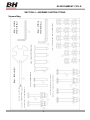
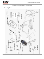
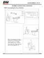
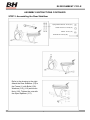
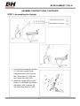
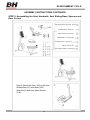
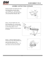
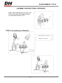
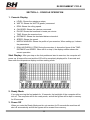
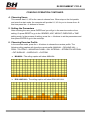
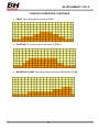
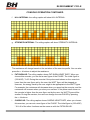
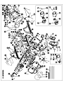
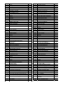
BH FITNESS R8 RECUMBENT CYCLE
OWNER’S MANUAL
BH FITNESS
20155 Ellipse
Foothill Ranch, CA 92610
Phone: 949-206-8152
Fax: 949-206-0013
Email: [email protected]
Web: www.%+)LWQHVV86$.com
BH 12/6/12
Revised: R8 RECUMBENT CYCLE
INTRODUCTION
Congratulations for selecting the R8 Recumbent Cycle as your primary source of fitness.
The BH Fitness R8 offers many exercise programs that benefit users of all levels and ages.
The R8 is designed to make your workouts more effective and enjoyable.
Please read this manual carefully before using the R8. This will allow you to get a full
understanding of all the features the BH Fitness Recumbent Cycle provides. If you have
questions or concerns, please contact BH FITNESS or any authorized BH FITNESS
distributors in your area.
BEFORE YOU BEGIN
It is very important to become familiar with the frequently used components of your R8.
1
R8 RECUMBENT CYCLE
TABLE OF CONTENTS
SECTION
PAGE
1. IMPORTANT SAFETY INSTRUCTIONS ...................................................... 3
2. ASSEMBLY INSTRUCTIONS ...................................................................... 4
3. COMPUTER CONSOLE .............................................................................. 17
4. CONSOLE OPERATION .............................................................................. 18
5. WARRANTY ................................................................................................. 25
2
R8 RECUMBENT CYCLE
SECTION 1
IMPORTANT SAFETY INSTRUCTIONS
Read all instructions before using the Recumbent Cycle.
Notice: Before using this or any other exercise equipment consult your family physician
or health care professional to develop a well planned exercise program to fit your health
needs. If you encounter any pain or breathing discomfort while working out, STOP!, and
consult a physician before continuing.
WARNING!
1.
2.
3.
4.
Keep children away from machine while in use.
Do not wear loose or dangling clothing while using the cycle.
Maximum user weight of this cycle is 300 lbs.
Keep a minimum clearance of 18” on each side and 24” at the rear of the cycle for
safety.
5. The cycle should never be left unattended when in operation.
6. Close supervision is necessary when this appliance is used by or near children, invalids,
or disabled persons.
7. Use this appliance only for its intended use as described in this manual.
8. Do not use any attachment not recommended by the manufacturer.
9. Never operate this appliance if it is not working properly. Call your service center for any
service concerns before taking your cycle in for repair.
10. Never drop or insert any object into any opening.
11. Do not use outdoors.
12. Do not operate where aerosol (spray) products are being used or where oxygen is being
administered.
13. This appliance is intended for household use only.
14. Clean with soap and slightly damp cloth only; never use solvents.
SAVE THESE INSTRUCTIONS
3
R8 RECUMBENT CYCLE
SECTION 2 - ASSEMBLY INSTRUCTIONS
Screws Bag
(41) Self Tapping Screw ST4x25 – 4 PCS
(108) Allen Bolt M8×15 - 16PCS (5) Waaher 18×9×2.0t – 16 PCS
(118) 6mm Allen
Wrench – I PCS
(116) 4mm Allen
Wrench – I PCS
(109) Screw M8×56 – 4 PCS (110) M8 Nut – 4 PCS (112) Spring
(114) Allen Bolt M8 45 - 2 PCS (143 M8 Nut-
Washer M8×2.0t – 4 PCS (113)Washer 20×9×2.0t - 4 PCS
(91) Allen Bolt M6×35 – 2 PCS
(117) Wrench - I PCS
×
×
2 PCS (142) Spring Washer M8 2.0t – 2 PCS
×
×
(5)Washer 18 9 20.t – 2 PCS
4
R8 RECUMBENT CYCLE
ASSEMBLY INSTRUCTIONS CONTINUED
Assembly Parts
Frame (1)
Handrail (59)
Seat (102)
Front Stabilizer (66)
Upright (80)
Rear Stabilizer (74)
Handrail (96)
Iron Bar (104)
Seat Sliding
Base (51)
Computer (97)
Plastic Pad (90)
Bottle (106)
Bottle Holder (107)
Right Rear Cover (49)
Left Rear Cover (48)
Foot Pedal (R) (120)
Foot Pedal (L) (119)
Backrest (103)
Chest Strap (126)
5
R8 RECUMBENT CYCLE
ASSEMBLY INSTRUCTIONS CONTINUED
STEP 1. Assembling the Front Stabilizer
Spring Washer M8×2.0t - 2PCS (112)
Washer 20×9×2.0 - 2PCS (113)
M8 Nut - 2PCS (110)
Screw M8×56 - 2PCS (109)
Refer to the drawing to the right.
Attach the Front Stabilizer (66) to
the Front Frame (1) with Bolts
(109), Washers (113), (112) and
Acorn Nuts (110). Tighten the nuts
with the Open Spanner (117).
6
R8 RECUMBENT CYCLE
ASSEMBLY INSTRUCTIONS CONTINUED
STEP 2. Assembling the Rear Stabilizer
Spring Washer M8×2.0t - 2PCS (112)
Washer 20×9×2.0t - 2PCS(113)
M8 Nut - 2PCS (110)
Screw M8×56 - 2PCS (109)
Refer to the drawing to the right.
Attach the Rear Stabilizer (74) to
the Frame (1) with Bolts (109),
Washers (113), (112) and Acorn
Nuts (110), Tighten the nuts with
the Open Spanner (117).
7
R8 RECUMBENT CYCLE
ASSEMBLY INSTRUCTIONS CONTINUED
STEP 3. Assembling the Upright
Washer 18×9×2.0t - 6PCS (5)
Allen Bolt M8×15—6PCS (108)
1. Connect the Handrail Pulse Wire
(17) and the Handrail Pulse
(upright section) (83). Connect
the Control Wire (L) (105) and
the Control Wire (M) (122).
2. Insert the Upright (80) into the
Frame (1). Assemble the frames
with Bolts (108), Washers (5)
and 6mm Allen Wrench (118).
8
R8 RECUMBENT CYCLE
ASSEMBLY INSTRUCTIONS CONTINUED
STEP 4. Assembling Computer Console
Step A: Unfasten the Screws (100) from
the Computer with Open Spanner (117).
Step B: Connect the wires from the
Computer. Connect (98) to (83) and (99)
to (122).
9
R8 RECUMBENT CYCLE
ASSEMBLY INSTRUCTIONS CONTINUED
STEP 5. Assembling the Seat, Handrails, Seat Sliding Base, Spacers and
Rear Covers
Self Tapping Screw ST4.0×25 - 4PCS (41)
Allen Bolt M635 - 2PCS (91)
Washer18×9×2.0t - 6PCS (5)
Allen Bolt M8×15 - 4PCS (108)
Allen Bolt M8×45 - 2PCS (114)
M8 Nut - 2PCS (143)
Spring Washer M8×2.0t—2PCS(142)
Step A: Attach the Seat (102) to the Seat
Sliding Base (51) with Bolts (108),
Washers (5) and 6mm Allen Wrench
(118).
10
R8 RECUMBENT CYCLE
ASSEMBLY INSTRUCTIONS CONTINUED
Step B: Assemble the Handrail (59) and
Seat Sliding Base with Allen Bolts
(114), Washers (5), (142) and Acorn
Nuts (143). Tighten with Open Spanner
(117) and 6mm Allen Wrench (118).
Step C: Turn the Handle (93) of the
Seat Sliding Base (51) in the direction
shown in the drawing to the right. Slide
the Seat Sliding Base onto the
Aluminous Tube (84) and then release
the Handle.
Step D: 1. Attach the Spacers (90) to
the Aluminous Tube (84) with Bolts (91)
and 4mm Allen Wrench (116).
2. Connect the Hand Pulse Wires (17),
(63) between the frame and handrail.
11
R8 RECUMBENT CYCLE
ASSEMBLY INSTRUCTIONS CONTINUED
Step E: Assemble Rear Covers (48), (49)
to the Frame with Self Tapping Screws
(41) and Open Spanner (117).
STEP 6. Assembling the Backrest
Washer 18x9x2.0t - 4PCS (5)
Bolt M8x15 - 4PCS (108)
12
R8 RECUMBENT CYCLE
ASSEMBLY INSTRUCTIONS CONTINUED
Assemble the Backrest (103) and the
Seat Sliding Base with Bolts (108),
Washers (5) and 6mm Allen Wrench
(118).
7. Assembling the Handrail
Washer 18x9x2.0t - 2PCS (5)
Bolt M8x15 - 2PCS (108)
Assemble the Handrail (96) and
Frame (1) with Bolts (108), Washers
(5) and 6mm Allen Wrench (118).
13
R8 RECUMBENT CYCLE
ASSEMBLY INSTRUCTIONS CONTINUED
8. Assembling the Bottle Holder
Step A: Unfasten the Bolt (82) from the
Upright (80) with Open Spanner (117).
Step B: 1. Attach the Bottle Holder
(107) to the Upright (80) with Bolt (82)
and Open Spanner (117). 2. Insert the
Bottle (106) into the Bottle Holder (107).
14
R8 RECUMBENT CYCLE
ASSEMBLY INSTRUCTIONS CONTINUED
9. Assembling the Pedals
Step A: Attach the Pedal Belt to the Pedal.
Step B: Tighten the Pedal in the arrow’s
direction in Picture B with Open Spanner
(117).
Step C: If needed, disassemble the Pedal in
the arrow’s direction in Picture C with Open
Spanner (117).
15
R8 RECUMBENT CYCLE
ASSEMBLY INSTRUCTIONS CONTINUED
10. Assembling the Book Shelf
Insert the Book Shelf (104) into the
Computer (97).
16
R8 RECUMBENT CYCLE
SECTION 3 – COMPUTER CONSOLE
Function
Keys
17
R8 RECUMBENT CYCLE
SECTION 4 – CONSOLE OPERATION
1. Console Display
a.
b.
c.
d.
e.
f.
g.
h.
i.
LEVEL: Shows the resistance steps.
WATTS: Shows the WATTS (power) consumed.
RPM: Shows the rolling speed.
CALORIES: Shows the calories consumed.
PULSE: Shows the heartbeat in beats per minute.
TIME: Shows the exercise time.
DISTANCE: Shows the simulated distance traveled.
SPEED: Shows the speed.
MATRIX WINDOW: Shows the profile of your exercise; When setting up, it shows
the parameters.
j.
ROLLING DISPLAY ITEM: During the exercise, it shows the figure of the TIME,
DISTANCE and SPEED. When set it or stop it, the display window shows the
current operation.
Start Display: After you step on the foot pedals and start to exercise, the computer will
power up. A beep will sound and the LCD will be completely displayed for 2 seconds and
then enter the temperature display and time setting mode.
2. Ready Mode
If you stop moving the foot pedals for 10 seconds, the backlight of the computer will be
turn off. The computer will be the ready mode, and all the figures will be kept in memory
for 50 seconds.
3. Power Off
When you enter the Ready Mode and do not exercise for 50 seconds the machine will
shut off automatically and all the figures will be erased from memory.
18
R8 RECUMBENT CYCLE
CONSOLE OPERATION CONTINUED
4. Choosing Users
This console has U1, U2 for the users to choose from. When step on the foot pedals
and enter the start mode, the computer will provide U1, U2 for you to choose from. At
this time press the – + buttons to choose.
5. Setting the Parameters
After choosing the user, press ENTER and you will go to the exercise mode or time
setting. Or press RESET to go to the GENDER, AGE, WEIGHT, EXERCISE or TIME
setting mode. In the process of setting, press the – + buttons to set the parameters and
then press ENTER to go to the next step.
6. Choosing Exercise Profile
In the exercise mode, press the – + buttons to choose the exercise profile. The
following rolling caption will show the current profile: MANUAL→ ROLLING HILL →
PEAK→ PLATEAU→ MOUNTAIN CLIMB→ HILL INTERVAL→ STRENGTH INTERVAL
→FAT BURN HR →CARDIO HR →CUSTOM.
a. MANUAL: The rolling caption will show MANUAL.
b. ROLLING HILL: The rolling caption will show ROLLING HILL.
19
R8 RECUMBENT CYCLE
CONSOLE OPERATION CONTINUED
c. PEAK: The rolling caption will show PEAK.
d. PLATEAU: The rolling caption will show PLATEAU.
e. MOUNTAIN CLIMB: The rolling caption will show MOUNTAIN CLIMB.
20
R8 RECUMBENT CYCLE
CONSOLE OPERATION CONTINUED
f.
HILL INTERVAL: the rolling caption will show HILL INTERVAL.
g. STRENGTH INTERVAL: The rolling caption will show STRENGTH INTERVAL.
The resistance will change based on the variations of the exercise profile. You can also
press the – + buttons to adjust the resistance.
h. FAT BURN HR: The rolling caption shows FAT BURN HEART RATE. When you
choose this exercise, you can set a max figure of the PULSE. The initial figure is
(220-AGE) * 0.65. During the exercise if the pulse result shown on the console is
lower than the max figure set by the user, the WATT figure will be stepped up.
However, the energy used by the user ought to be appropriate to the WATT figure.
For example, the resistance will decrease when you speed up the exercise, and the
resistance will increase when you slow your exercise. If the pulse result shown on
the console is higher than the max figure set by the user, the WATT figure will be
smaller. During the exercise, the user can change the max PULSE by pressing
the – + buttons.
i.
CARDIO HR: The rolling caption shows CARDIO HEART RATE, when you choose
this exercise, you can set a max figure of the PULSE. The initial figure is (220-AGE)
* 0.8. All of the other functions are the same as with the FAT BURN HR.
21
R8 RECUMBENT CYCLE
CONSOLE OPERATION CONTINUED
j.
CUSTOM: The rolling caption shows CUSTOM. When you choose this exercise,
you can set the resistance yourself. You can set the resistance in different steps by
pressing the – + buttons, then press ENTER to go to the next step. If you press and
hold ENTER, it will exit the setting of the CUSTOM resistance and go to the next
setting.
7. Setting the Exercise Time
The preset time is 20:00. You can press the – + to set the exercise time. When the time
reaches 0:00, a beep will sound to indicate the exercise time is up.
8. Description of the Keys
a. RESET Key
During the off status, press this key you can reposition all the figures, except the
WORK LEVEL in the CUSTOM PROGRAM.
In the pause mode, press this key to choose another mode. In the Off position,
press this key and hold it to enter the start mode.
b. QUICK/START Key
After you start the machine, press this key to enter the Manual mode at any time.
The time begins at 0:00 and begins to count up.
c. ENTER Key
When setting values, press this key to confirm the value and go to the next step.
d. START/STOP Key
Press this key while exercising to stop the current exercise profile from updating.
Press it again to continue the last exercise. In the Off mode press the RESET key
to clear all the values.
e. – Key
Press this key to lower the resistance while exercising. When setting parameters,
press this key to lower the value.
f. + Key
Press this key to increase the resistance while exercising. When setting
parameters, press this key to increase the value.
g. RECOVERY Key
By pressing this key and then grasping the pulse sensors on the handlebars you
can start the recovery pulse feature which provides a fitness rating at the end of
the workout.
Press this key and the computer will start a 10 second preparation function. At this
time the user can stop exercising. After 10 seconds, the computer will begin the
recovery pulse test for 60 seconds. If in the 10 second preparation time, the
computer PULSE shows 0, the computer will return to exercise mode.
22
R8 RECUMBENT CYCLE
CONSOLE OPERATION CONTINUED
In the 60 second recovery pulse test, if the PULSE shows 0, the computer will
return to the exercise mode after 60 seconds.
During the 60 second recovery pulse test, the user can repress the RECOVERY
key to stop the recovery pulse test and return to the exercise mode.
After the 60 second recovery pulse test, the console will show A+, A, B+, B, C+, C
to advise the user of the test results.
A+
A
B+
B
C+
C
Best
Very Good
Good
Common
Bad
Very Bad
9. Function Table
ITEM
RANGE
DEFAULT
MEMORY REPOSITION
FIGURE
EXPLANATION
When you set 0:00 it will
count up. When you set it to
05:00~99:00, it will count
down, and when it reaches
0:00 it will beep.
TIME
0:00~99:59
20:00
No
Yes
DISTANCE
0.00~99.99
0.00
No
Yes
PULSE
0~255BMP
0~255
BMP
No
CALORIES
0~999CAL
No
WATT
0~999
No
RECOVERY
A+~C
No
RPM
0~250
No
AGE
10~100
30
Yes
Preset 10~100 years
50~300LB
150LB
Yes
Preset 50~300 Pounds
20~150KG
70KG
Yes
Preset 20~150KG
WEIGHT
(LB)
WEIGHT
(KG)
You can set the max
heartbeat
Yes
A+, A, B+, B, C+, C
10. Metric or English Display
In the Off mode, press the START/STOP and – keys at the same time and then start
pedaling. When the computer powers up it will enter the work mode. Press ENTER and
you can choose from METRIC and ENGLISH using the – + keys. KGS is the metric and
LBS is for the English system. Press ENTER to go to the start mode.
23
R8 RECUMBENT CYCLE
CONSOLE OPERATION CONTINUED
11. Batteries
The console has 4 rechargeable batteries in it. When you exercise, the generator
automatically charges the batteries. When you stop exercising the batteries will take
over to power the display.
CAUTION: Use only rechargeable batteries of the same type and voltage as those
supplied with your bike. DO NOT use alkaline batteries as they will be damaged when
charged.
24
ITEM
1
2
5
6
7
8
9
10
11
12
13
14
16
17
21
22
24
25
26
Description
Frame
Bearing 6203ZZ
Washer ∮18x∮9x2.0t
Belt Wheel(∮240x19t,liugou)
Magnet(∮15X7T)
Crank Post + Iron Plate
C-Clip(∮17)
Allen Bolt(M6xP1.0x15)
Spring Washer(M6x1.5t)
Wave Washer(∮22x∮17.5x0.3t)
Bushing
Belt(37"J6)
Controller
Hand Pulse Wire-Frame Part
Electrical Grinding Wheel
Washer ∮15x∮7x2.0t
Straight Crank(Left)
Straight Crank(Right)
Crank Cover
27
Allen Indented Screw (M8x1.25x20mm,13 sides)
28
29
30
31
32
33
34
35
38
39
40
Idler Fixing Iron Plate
C-Clip (∮10 shaft)
Counter Sink Philips Screw(M5x20)
Idler Flex Spring
Adjustment Screw
Indented Nut(M6)
Bushing
Bearing 6000ZZ
Left Front Chain Cover
Right Front Chain Cover
Truss Philips Screw(M4x12)
Counter Sink Philips Self Tapping
Screw(ST4x25)
Plastic Pad
Truss Philips Screw(M6x25)
CKS Hex Screw(M8x18)
Left Rear Chain Cover
Right Rear Chain Cover
Rear Decoration Cover-Left
Rear Decoration Cover-Right
Cushion Sliding Tool
Bushing
41
42
43
45
46
47
48
49
51
52
53
54
55
56
57
58
59
60
61
62
63
64
65
66
67
68
69
70
71
Wheel
Pan Head Hex Screw
M10 Acorn Nut(17 sides)
Bushing
Spring
End Cap
Handle
Truss End Cap
Round Head Philips Self Tapping
Screw(ST4.0x25)
Hand Pulse Sensor
Hand Pulse Wire-Handle Part
HDR Foam Grip
Wire Clip
Front Stabilizer
Front Stabilizer Inner Bushing(Left)
Front Stabilizer Outer Bushing(Left)
Plastic Wheel
Truss Philips Self Tapping Screw(ST4.0x15)
Truss Philips Screw(M4x15)
72
Front Stabilizer Inner Bushing(Right)
73
74
75
Front Stabilizer Outer Bushing(Right)
Rear Stabilizer
Rear Stabilizer Outer Bushing
QTY
1
2
26
1
1
1
1
4
8
2
1
1
1
1
1
4
1
1
2
2
1
1
3
1
1
1
3
3
1
1
10
16
1
1
8
1
1
1
1
1
8
8
6
6
1
1
1
1
2
2
2
1
2
2
1
1
1
2
4
2
1
1
1
2
ITEM
76
77
78
79
80
81
82
83
84
85
86
87
88
89
90
91
92
93
94
95
96
97
98
99
100
101
102
103
104
105
106
107
108
109
110
112
113
114
116
117
118
119
120
122
124
126
130
136
137
142
143
144
145
146
147
149
151
152
153
154
155
156
157
158
Description
Adjustable Supporter
Adjustment Knob
Foot Pad
Truss Philips Screw(M4x12)
Upright
Foam Grip( ∮31.8x3.0tx175mm)
Truss Philips Screw(M5x15)
Hand Pulse Wire-Upright Part
Aluminum Tube
M6 Nut
Counter Sink Philips Screw(M4x15)
Runner Iron Plate
Runner Fixing Iron Plate
Counter Sink Philips Screw(M4x10)
Plastic Pad
Truss Hex Screw(M6x35)
Inner Fixing Plate of Aluminum Tube
Adjustment Handle
Black Bushing
Turn Tool
Handrail
Computer
Hand Pulse Wire
Upper Control Wire
Truss Philips Screw(M5x10)
Television Computer
Saddle
Backrest
Bookshelf Iron Plate
Lower Control Wire
Transparent Bottle
Bottle Shelf
Truss Hex Screw(M8x15)
Truss Carriage Screw(M8x56)
M8 Acorn Nut
Spring Washer(M8x2.0t)
Washer ∮20x∮9x2.0t
Truss Hex Screw�(M8x45)
4mm Hex Wrench
Open Spanner
6mm Hex Wrench(65x25)
Pedal-Left
Pedal-Right
Middle Control Wire
CKS Hex Screw(M6xP1.0x15)
Washer∮18x∮7x2.0t
CKS Hex Screw W/Washer(M5x16)
Washer
Spring Washer(M8X2.0T)
Acorn Nut (M8)
Argentine Decal(Left) of Pedal
Argentine Decal(Right) of Pedal
Argentine Decal(Left) below Saddle
Argentine Decal(Right) below Saddle
Truss End Cap
Generator Connecting Wire
Inductance Connecting Wire
Belt(2.5X150)
Belt(4.8X300)
Spring Hook
Flat Head Hex Eccentricity Screw
SAG3515
Nylon Nut M8;13 sides
Screw Cover(PCZ18175)
QTY
2
2
2
4
1
2
2
1
1
4
3
1
3
3
4
4
2
1
1
1
1
1
2
1
6
1
1
1
1
1
1
1
16
4
4
4
4
2
1
1
1
1
1
1
4
1
1
1
2
2
1
1
1
1
2
1
1
1
4
1
2
2
2
WARRANTY
LIMITED LIGHT COMMERCIAL WARRANTY
BH North America will repair or replace, free of charge, at its option, parts that are
defective as a result of material or workmanship. Seven (7) year replacement warranty
coverage on frame and five (5) years on other parts. Labor warranty coverage is one (1)
year. Warranty covers the original consumer purchaser only.
LIMITED RESIDENTIAL WARRANTY
BH North America will repair or replace, free of charge, at its option, parts that are
defective as a result of material or workmanship. Lifetime replacement warranty coverage
on frame and ten (10) years on other parts. Labor warranty coverage is two (2) years.
Warranty covers the original consumer purchaser only.
THIS WARRANTY DOES NOT COVER
• Pre-delivery set-up.
• Components that require replacement due to dirt or lack of regular maintenance.
• Expendable items which become worn during normal use.
• Repairs necessary because of operator abuse or negligence or the failure to operate
and maintain the equipment according to the instructions contained in the Owner’s
Manual.
For more detailed warranty information or to register your product warranty easily
online, visit our website at: www.BHFitnessUSA.com
FOR WARRANTY REPAIRS, PLEASE DO NOT TAKE YOUR MACHINE
BACK TO THE RETAIL STORE. CONTACT BH FITNESS FIRST.
BH North America Corporation
20155 Ellipse
Foothill Ranch, CA 92610
Phone: 949.206.0330; Toll Free: 866.325.2339; Fax: 949.206.0013
Web: www.BHFitnessUSA.com
Mon - Fri 8am - 5pm PST