1
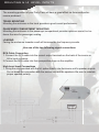
By
AMPP210H / AMPP212H
OWNER’S MANUAL
Contents of Carton
•
•
•
•
•
•
•
Amplifier
Enclosure
Warranty Card
Amplifier Wiring Kit
Remote Bass Knob
Sticker
Operations Manual
1. Make sure to carefully read and understand the instructions before attempting
to install your new Audiobahn tube.
2. Before making any electrical connection, make sure that you disconnect the
battery’s ground cable to prevent the possibility of short circuit or damage to
your electronic equipment.
3. For easier assembly, we suggest you run all wires prior to mounting your amplifier and/or enclosure.
4. Route all of the RCA cables close together, and away from any power wires.
5. Think before you drill! Be careful not to cut or drill into gas tank, fuel lines,
brake or hydraulic lines, vacuum lines, or electrical wiring when working on
any vehicle.
6. Avoid running wires over or through sharp edges. Use rubber or plastic grommets to protect any wires routed through metal, especially the firewall.
7. ALWAYS protect the battery and electrical system from damage with proper
fusing.
8. When grounding to the chassis of the vehicle, scrape all paint from the metal
to ensure a good clean ground connection. Grounding connections should be
as short as possible, and always be connected to metal that is welded to the
main body or chassis of the vehicle.
Mounting & HI LEVEL INPUTS
The mounting position of your Party Pack will have a great effect on the sound performance produced.
TRUNK MOUNTING
Mounting the enclosure in the trunk provides a good overall performance.
PASSENGER COMPARTMENT MOUNTING
Mounting the enclosure in the passenger compartment provides optimum sound, but reduces the area for passenger seating.
LOADING
Facing the enclosure towards a wall will increase the low frequency sounds.
Use one of the two following signal connections
RCA Cable Connection
1. Connect the RCA cable into the correct output terminals on the back of the source or
Hi/Lo level converter.
2.Connect the RCA cable into their perspective plugs on the amplifier.
High Level Input Connections
1. Using the cord provided with the kit, splice directly into the source unit’s speaker outputs.
Do not break the connection with the source unit and the speakers. Be sure to maintain
proper speaker polarity.
REAR
FRONT
2
GND
3
REM
POWER
10
REMOTE
4
BATT
9
ON OFF
PHASE
8
FUSE
PROTECTION
POWER
MIN
5
MAX
LEVEL
R
L
LCH
LOW INPUT
1
SPEAKER
6
7
RCH
R
L
LINE OUT
RJP Designs
+R- G - L+
HIGH INPUT
Controls And Functions
Controls And Functions
1. Speaker Terminals
SPEAKER
These chrome plated connectors can accept from 16 to 8 gauge wire. Be careful to observe proper polarity when
connecting the cables
2. B - Terminal (Chassis ground)
POWER
GND
REM
BATT
To avoid unwanted ignition noise caused by ground loops, it is essential that the amplifier be grounded to a
clean, bare, metal surface of the vehicles chassis.
Note: GROUND WIRE SHOULD NOT BE EXTENDED MORE THAN 3 FT. (1 METER)
3. Remote Turn-On Input
POWER
GND
REM
BATT
To remote or power antenna output of car stereo. This amplifier is turned "ON" remotely when the vehicle's stereo
is turned "ON".
Note: IF YOUR RADIO DOES NOT HAVE +12 VOLT OUTPUT LEAD WHEN THE RADIO IS TURNED ON, THE
"REMOTE" TERMINAL ON THE AMPLIFIER CAN BE CONNECTED TO THE VEHICLE'S ACCESSORY
CIRCUIT THAT IS LIVE WHEN THE KEY (IGNITION) IS "ON".
4. B+ Terminal (Battery Positive)
POWER
GND
REM
BATT
Controls And Functions
5. Input Sensitivity Adjustment
MIN
MAX
This control adjusts the amplifier's sensitivity to match the signal strength coming from the source unit. Input
sensitivity is variable from 200 Millivolts to 8 volts. Clockwise increases sensitivity. Counterclockwise decreases
sensitivity. THE KNOB IS NOT A VOLUME CONTROL. A lower signal level will require increased sensitivity for
full power. A higher signal will require decreased sensitivity.
6. Low Level Input RCA Jacks
These inputs are for signal cables from the source unit or other processor. Always use high quality shielded RCA
cables.
7. Low Level OUT RCA Jacks
The LINE OUT allows you to build multiple amplifier systems without having to use splitter cords to distribute the
signal. Now it is a simple matter of bridging one set of RCA cables into the first amplifier, then using the line out
RCA jacks as the feed to the next amplifier.
8. LED indicator (Status)
POWER
PROTECT
-PWR (Power) : This BLUE LED will illuminate when the amplifier is turned "ON". If it fails to illuminate, check the power connections to
the amplifier and fuses.
- PROT (Protection) : The amplifier protection circuitry will disable the amplifier if input overload, short circuit, or extremely high
temperature conditions are detected. When the protection mode is in operation, the LED indicator on the side panel will be illuminated,
indicating the amplifier has gone into a self-preservation mode.
If you observe that the protection LED is lit, please check the system carefully to determine what has caused the protection circuit to
engage. The amplifier shut down due to a thermal overload condition, please allow it to cool down before restarting. If the amplifier shut
down because of an input overload or short circuit, be sure to repair these conditions before attempting to power up the amplifier again.
Controls & Functions
9. Phase Shift control
10. Remote Bass Knob Port
REMOTE
Bass Boost Control (MIN / MAX) : Optional
REMOTE BASS BOOST KNOB
Mounting and Installation
1. Using the screws provided with the kit, find a location under the dash, center console,
or a place that gives easy access to the remote bass boost knob.
2. Plug in the supplied cord into the back of the bass boost knob.
Adjusting the Level
To adjust the level setting, first turn the amplifier gain all the way down. Then turn the
source volume up until distortion is audible, and then turn it down until distortion is inaudible. Next, turn the amplifier level setting until once again distortion is audible, and then
back it down until distortion is inaudible.
Adjusting the PHASE
If the enclosures woofers are facing towards the trunk lid the phase switch should be set to
180º, if the enclosures woofers are facing towards the front of the vehicle the phase switch
should be set to 0º.
Specifications
Model NumberAMPP210HAMPP212H
Power RMS600 Watts800 Watts
Achievable Power
1200 Watts
1600 Watts
Frequency Response:28Hz-1kHz26Hz-1kHz
EnclosureDual 10”Dual 12”
Enclosure Dimensions:
Height:15.25”15.5”
Width:28.25”31.62”
Length:15.5”15.5”
Common Features
A/B Amplifier • HI -Level Inputs • Tiffany Style RCA Jacks • RCA
Throughput Connections • Phase Shift Control • Thermal Protection •
Nickel plated terminal blocks • Proprietary Aluminum Heat Sink • Additional Faraday Ventilation • Co-balt Blue Illumination • THD 0.2% • S/N
Ratio >100dB • Input Sensitivity 0.3 - 8V • Powerdercoated Topplate •
17’ 10awg. Power Cable • 3’ 10awg. Ground Cable • 17’ 18awg. Remote
Turn-On Wire • 17’ RCA Cable • ATC Fuse Protection • MDF (Mediumdensity fiberboard) Construction w/ Black Carpet • Woofer Grill • Slot
Port Enclosure • Accessory Package w/ wire-ties
Troubleshooting
SYMPTOMS
NO SOUND
AMP NOT
SWITCHING
ON
Is the power
LED illuminated ?
( NO )
Check fuses in amplifier.
Be sure Turn-on lead is connected
Check signal leads. Check gain
control.
Check Tuner/Deck volume level.
Clean contacts on fuse holders.
Is the Diagnostic
LED illuminated ? ( YES )
Check for speaker short or
Amplifier overheating.
No power to power wire
Repair power wire or connections.
No power to remote
wire with receiver on
Check connections to radio.
Fuse broken
AUDIOBAHN
CURE
CHECK POINTS
Replace fuse.
Inspect for short circuit or an
open connection.
NO SOUND
IN ONE
CHANNEL
Check Speaker Leads
AMP
TURNING OFF
MEDIUM/HIGH
VOLUME
Check speaker load
impedance
Be sure proper speaker load
impedance recommendations
are observed.
(If you use an ohmmeter to check
speaker resistance, please
remember that DC resistance and
AC impedance may not be the
same.)
STATUS
LAMP ON
Temperature shut down
Turn radio down
Check Audio Leads
Speaker wires short
Reverse Left and Right RCA inputs
to determine if it is occurring
before the amp.
Separate speaker wires and
insulate
UNIVERSAL SUBWOOFERS