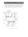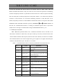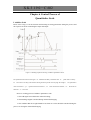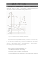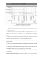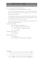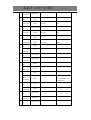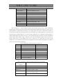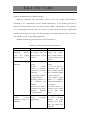
1
XK3190
C 602
XK3190-C602
Weighing Indicator
User Manual
襦Version 1.03襤
襤
XK3190
C 602
Content
Preface
Chapter 1 General……………………………………………………
Chapter 2 Main Parameters……………………………………………
Chapter 3 Installation, Interface & Communication Format…………
Chapter 4 Parameters Setting and Calibration…………………………
Chapter 5 Operating Instruction of Quantitative Scale…………………
Chapter 6 Control Process of Quantitative Scale ………………………
Chapter 7 Operating Instruction of Catchweigher……………………………
Chapter 8 Application Examples of Catchweigher……………………………
Annex A Error Prompt Message……………………………………………
Annex B Schematic Diagram of Relay Board………………………………
Annex C Scoreboard Data Waveform Graph and Format………………
Annex D Data Format of Communication Port (1)…………………………
Annex E Data Format of Command-Response Mode of Communication Port (2)………………
Annex F Explanation on Print Format……………………………………
Annex G Troubleshooting of General Problems…………………………
Annex H Safety Instructions………………………………………………
XK3190
C 602
Preface
Instruction for use of manual
This manual is for reference by the operators and installers of XK3190-C602 indicator during
their operation or installation and testing. Chapter 1 and chapter 2 of this manual introduce the
technological features and parameters of the indicator in a general manner. Chapter 3 and chapter
4 describe the installation, parameter setting and calibration methods which can be referred to by
installers and repairmen as well as by on-site operators who need to adjust the working modes and
parameters of the indicator. Chapter 5 gives out the details of on-site operation methods when the
indicator is used to control quantitative scale. Chapter 6 explains the ways and working
procedures of the indicator when it is used to control quantitative scale, which can assist installers
and operators in understanding the setting of each parameter. Chapter 7 covers the on-site
operation methods of indicator when it is used to control catchweigher. Chapter 8 focuses on the
ways and working procedures of the indicator when it is used to control catchweigher, which can
help installers and operators understand the setting of each parameter. The annexes provide
information for error prompt message, communication format, and general problems.
During use of this manual, you may browse it first, and then select the contents related to
your current task while omitting the part not concerned. After you have got a general
understanding of the indicator, you can read it once again carefully.
The following glossaries are used in the manual:
Parameters are short for configuration parameters. The configuration parameters of quantitative
scale include the data setting of timing constant, batching value, and lead, while that of
catchweigher includes the data setting of timing constant and catch weight limit. Configuration
parameter 2 stands for the second set of parameters. Please note that only嫐SET 2嬪parameter can
be separately configured as 5 sets, while 嫐SET 1嬪can only have 1 set.
Lead During the feeding of quantitative scale, the weight of material on the load carrier is less
than the weight of material delivered by the feeder since part of the delivered material is still in the
XK3190
C 602
air and has not reached to the load carrier. To obtain the predetermined material weight, it is
necessary to turn off the feeder in advance. The weight involved in the leading is called a lead. For
C602, “self-correction of lead” function can be activated to ensure the accuracy of final weight.
Gradual feed When the feeding to quantitative scale is finished, the material weight is less than
the predetermined weight and the difference is beyond the tolerance, the indicator can start slow
feeding repeatedly and shortly to make the loaded weight approach to the predetermined value.
Add signal is short for “adding input signal is allowed”. Only when the add signal is valid can the
C602 output feeding control signal.
Discharge signal is short for “discharge input signal is allowed”. Only when discharge signal is
valid can C602 output discharge control signal.
Zero zone is the weight limit in additive scale which is used to judge whether the material in
hopper is completely discharged.
1. During discharging, it is deemed completed when the indicator shows the gross weight is
below zero zone.
2. The indicator can print and totalize only when the material weight is above zero zone.
For catchweigher, the self-control catchweigher can start weighing process only when the
weight signal is above zero zone and can print and sum when the calculation result of material
weight is above zero zone.
Additive scale is the quantitative scale used for batching control of added material weight in load
carrier (like hopper etc), for example, the hopper-type quantitative packing scale.
Subtracting scale is the quantitative scale used for batching control of subtracted material in the
load carrier (like hopper). It is also called weight loss scale.
Negative scale is the indicator to measure the weight removed from the load carrier. Subtracting
scale works as negative scale during feeding.
Channel is the range of object weight. C602 indicator can be divided into 5 weight ranges, also
called 5 channels. Each channel has 1 corresponding switch output signal.
Out-of-tolerance treatment When it is valid and the materials fed by quantitative scale is less
than the lower limit of batching value (subtracting tolerance of batching value), while there is no
gradual feed function, or when the fed material is more than the upper limit of set value (additive
tolerance of batching value), the quantitative scale will stop running, waiting for manual treatment.
When the weight meets the tolerance requirement, the quantitative scale will resume the
interrupted work.
Peak holding When the catchweigher captures an object weight, it will be displayed until the
weight of next object is captured. The main display or auxiliary display can be selected to show
XK3190
C 602
the captured object weight.
Initial zero-setting is the first zero-setting operation after startup. It can be set as automatic
zero-setting upon startup (initial) or manual zero-setting. If zero-setting upon startup is
prohibited, the indicator maintains the zero point at shutdown. The initial zero-setting range can
be selected and generally ±10%Max is set. If the variation of zero point of scale exceeds the
initial zero-setting range, initial zero-setting cannot be carried out. The zero-setting range
(generally ±2%Max) is based on the zero point determined during initial zero-setting.
Main display The 6-digit 0.56 LED digital tube in upper part of display window and the
indicators on both sides are main display of C602 indicator, which is used to display major
contents such as weight and set value etc..
Auxiliary display The 6-digit 0.4 LED digital tube in lower part of display window is auxiliary
display of C602 indicator, which is used to display accumulative value, summation, date, time,
operation procedure etc.. Parameters are prompted during parameter setting and error signal is
displayed in case of error prompt.
XK3190
C 602
Chapter 1 General
The XK3190-C602 weighing indicator adopts Cortex M3 32-bit processor and high-precision
1-
A/D convertor to carry out conversion display for weight signal. The maximum conversion
speed can reach up to 200/s. The display can be easily connected with resistance strain gauge
transducer to form batching scale and quantitative packing scale etc., suitable for various
applications where high-speed and high-precision weighing control are required.
Major functions and features of XK3190—C602 weighing indicator:
(1) Four optional working procedures of additive scale, subtracting scale, self-control
catchweigher and external control catchweigher. The catchweigher can be set as general
catchweigher and peak holding scale, with excellent versatility. As quantitative scale and
catchweigher, it can store 5 sets of parameters.
(2) AD speed can be set, and digital filtering intensity can also be set.
(3) Save, check, and delete weighing record, with power-off data protection function.
(4) Accurate clock, calendar, automatic leap year and leap month display, not affected by
power-off.
(5) Self-control function and various operation error messages.
(6) The standard configuration includes 8 optical isolation switch input, of which 2 channels
are used as high speed counting input, encoder input or interrupt (i.e. quick response) input; 8
optical isolation switch output (with external relay box optional). The standard program of
indicator can carry out batching value control for two materials.
(7) Expansion is possible for switch value input and output. With the connection of one
external IO expansion box, 8 additional switch input and 8 switch output can be provided. 4 IO
expansion boxes can be connected in series as a max..
(8) Two independent asynchronous serial communication interfaces, with interface 1 of
RS232 and interface 2 of RS232/RS422/RS485 optional. Two communication modes are available:
continuous send and command response.
(9) Parallel/serial print interface, available for connection with various printers.
(10) Chinese and English weighing record, accumulative value, parameters or calibration
parameters can be printed.
(11) Optical isolation 20mA current loop scoreboard display interface.
(12) 1 optical isolation 4 ~ 20mA/0 ~ 5V/0 ~ 10V analog output (optional).
XK3190
C 602
Chapter 2 Main Parameters
Indicator model
XK3190—C602 weighing indicator
Precision degree
Level 3
Max.
verification
scale
nind=3000
interval
Min. input signal voltage
of e verification scale
12V
interval
Input signal range
3mV
15mV
Bridge power of weighing
DC 5V 80mA
load cell
Connecting
type
of
of long wire
weighing load cell
Max.
cable
6-wire system, automatic compensation
length
of
100m / 0.5mm2
weighing load cell
Material: copper
Display
Main display has 6-digit LED digital
tube, with character height of 0.56 in.
Auxiliary display has 6-digit LED digital
tube, with character height of 0.4"
23 status indicating lamps
Display scale interval
1/2/5/10/20/50 optional
0 ~ 3 decimal digits
Clock
Yes. To show time and date
Keyboard
Soft push switch is adopted, including 6
buttons.
Max.
data
memory
+ weight data
capacity
Scoreboard
8064 weight data or 4032 groups of time
display
interface
Serial output is adopted. 20mA current
loop signal can be connected to various
sizes of scoreboard display
Communication interface
2 serial RS232C, one of which can be set
as RS422/RS485
Baud rate 600 ~ 57600bps optional.
XK3190
C 602
Parallel output port: to be connected with
Print interface
micro printer, LT800, KX-P1121 or
LQ1600K line printers.
Serial interface: to be connected with
serial interface printer
8 optical isolation and open collector
Switch output
switch output with max. control voltage
330V DC, current 3100mA, total current
of 8 channels 3200mA
Relay output (with relay
Number of relay: 8
Contact capacity: 220VAC / 28V DC
box)
0.5A
8 optical isolation input, input signal +12
Switch input
~ +24V DC, the pulse width shall be
above 0.2s
I0 and I1 can be configured as one of
four input modes: common input, 2
high-speed counting input, 1 decoder
input or 2 interrupt input, the maximum
counting
frequency
of
high-speed
counting and coder input mode is
10KHz.
Expansion
of
input and output
Switch
Each expansion module has 8 optical
isolation input with input signal +12 ~
+24V DC
8 optical isolation relay output with
contact capacity 220V AC/28V DC
0.5A
The expansion module shall be provided
with stable external 12V power supply,
with maximum working current of
300mA
C602 indicator can be connected to 4
switch expansion modules as max..
Analog output
Optical isolation output. It can be set as
one of three modes 4-20mA / 0-5V /
XK3190
C 602
0-10V.
Precision degree
30.2%FS
Load capacity:
4-20mA
max. load resistor 2504
0-5V / 0-10V
output impedance 3 14
Working power supply
110 230V AC 50/60 Hz
Temperature
0
humidity
of
and
40
390 RH
-20 50
390 RH
working
environment
Temperature
humidity
transportation
and
of
and
storage
External dimension
Housing: 150 * 75 * 105 (mm) (width *
height * depth)
Panel: 172 * 93 * 3 (mm) (width *
height* thickness)
Dimension of installation hole: 152 * 77
(mm)
Weight
About 0.8kg
XK3190
C 602
Chapter 3 Installation, Interface & Communication Format
I. Schematic diagram of front panel and back panel of indicator
Indicator lamp
for output
Indicating lamp for
Display window
operating status
Indicator lamp
for weighing
status
Keyboard
Indicator lamp
for input
signal
Figure 3
1 Schematic Diagram of Front Panel
XK3190
Connecting
terminal of power
C 602
Connecting terminal of
switch output
Connection
terminal of switch
Connection terminal of
analogue output
Connection terminal
Calibration
Connecting
switch
terminal of
Interface of
parallel printer
Figure 3
2 Schematic Diagram of Back Panel
of weighing load cell
XK3190
C 602
II. Schematic diagram of main panel and power panel
IO expansion
socket
Expansion
Socket of AD
Inter-panel
socket
module
connector
ISP jumper or toggle
RS232/RS485
switch
optional jumper
JTAG interface
Figure 3-3 Schematic Diagram of Main Panel
XK3190
C 602
Inter-panel
High voltage area
connector
in power panel
Setting jumper of
analogue output
Figure 3-4 Schematic Diagram of Power Panel
XK3190
C 602
Attention: the indicator shall have sound and reliable earthing
protection so as to ensure the operation stability and safety of
operator.
Installation method of indicator
Unscrew two M4 fastening screws on both sides at back of the indicator, remove the binding,
insert the indicator into the installation hole, insert the binding again and fasten it with M4 screws.
Disassembly and assembly of indicator
When changing analogue output mode or RS422/RS485 upper and lower resistance or the
terminating resistance, the indicator should be opened to adjust the position of corresponding
jumper at the main board or power panel. Please carry out the disassembly and assembly of the
indicator according to following method to avoid any damage.
Attention: many elements in the indicator are sensitive to static electricity. Please get rid
of charge in human body before disassembling the indicator by touching wall or other
earthed object so as to protect the indicator against damage by static electricity.
Disassembly method: remove all screws in back panel of indicator, remove the back panel,
carefully draw out the upper power panel and the lower main board to adjust corresponding
jumper.
Assembly method: carefully insert the main board and power panel into the slots in the
housing. When it is about to be fully inserted, and encounters significant resistance, as if blocked
by something, at this time, do not insert it forcedly, instead, shake the circuit board and carefully
insert it. If fails, check whether the contact pin of connector is deformed and whether there is any
abnormity in double socket in the display panel. When circuit board is inserted to its place, mount
the back panel and fasten all screws. Please note that the screws in the four corners are
self-tapping screws and the rest are M3 * 6 SL screws.
XK3190
C 602
III. Connection between load cell and indicator
1. 7-pin electrical male plug are adopted for connection of load cell. Figure 3-5 shows the
meanings of each pin.
2. When junction box is used to connect several load cells or extend the cable of load cell,
six-wire connecting method must be adopted. When 1 load cell is used and the cable is not
extended, four-wire system can be adopted. Under this condition, it is necessary to short connect
the EX+ and SEN+ with EX- and SEN- respectively.
3. The load cell and indicator should be reliably connected and the shielded line of load
cell should be reliably connected with GND terminal. The connecting line can not be plugged
in and out when the indicator is powered on in order to prevent any damage to the indicator
or load cell by static electricity
4. The load cell and indicator are both static sensitive equipments, so anti-static measures
must be taken during the use. It is strictly forbidden to carry out welding operation or other
operations with high current on the weighing platform. In the stormy season, lightening
prevention measures must be taken reliably to prevent any damage to load cell and indicator
caused by lightening stroke, and to guarantee the personal security of operators and safe
running of weighing devices and relative equipments.
In the figure: EX+, EX-: excitation power supply; SEN+, SEN-: excitation feedback; SIG+, SIG-: load cell output
signal; GND: shield
Figure 3-5 Connection Diagram of Load cell
XK3190
C 602
IV. Printer interface
1. Parallel printer interface adopts the standard 25-pin D type jack socket. Figure 3-6 shows
the meaning of each pin. The indicator can be connected to printer by standard parallel
interface printer cable. The 13th pin is +5V output which can be used to connect micro printer
with peak current below 2A.
+5V
BUSY
13
11
12
25
24
D7
10
23
D6
9
22
8
21
20
D5
D4
7
6
19
D3
D2
5
18
D1
4
17
D0
2
3
16
ST
15
1
14
ÐÅ
ºÅµØ
Signal ground
Figure 3-6 Printer Interface
2. Serial printer interface uses the communication interface RS-232 (1). See RS-232 (1) in
(Fig. 3-7) for the meaning of each pin. Busy means the printer is busy.
Setting of printer
Correctly set the parameters 7, 8, and 9 (see table 4-3 in chapter four) of
SET 1 according
to the printer model and printing language (Chinese or English). If the printer not listed in the
table is to be used, try to select the model with similar printing command format with those listed
in the table.
Selection of micro printer
It is suggested to adopt the mirco printer with Chinese library, available for printing at least 16
English charanters in 1 line. When micro printer without Chinese character database is used, only
English printing mode is available for selection.
The micro printer shall support the following commands:
Switch to Chinese printing: ESC 8 n (0x1b, 0x38, n)
Reverse printing: ESC C n (0x1b, 0x63, n)
Our company can select the micro printer for customers, which has been verified in the C602.
XK3190
C 602
V. Scoreboard display interface
The scoreboard display interface is the 20mA current loop interface which is capable of
driving various scoreboards.
Please refer to appendix C for the data format and oscillograph of scoreboard display interface.
In the figure, DP+ and DP- are the 20mA current loop interface of scoreboard.
Figure 3
7 Serial Communication and Scoreboard Display Interface
VI. Serial communication interface (1)
Serial communication interface (1) is RS232C interface which is capable of transmitting AD
switch code or weight data to the PC at high speed, the data rate is equal to AD switching speed.
The function of serial interface (1) can be set by
set by
SET 1
SET 1
parameter 6A and its baud rate can be
parameter 5A. Refer to appendix D for data format.
Serial interface (1) can also be used as the drive interface to connect the serial interface
printer. The XOFF/XON flow control protocol can be adopted and Busy signal can be used to
control the transmission of printing data.
VII. Serial communication interface (2)
Serial communication interface (2) can transmit data to PC as well as receive control
command issued by the PC and set parameter. Serial communication (2) can communicate with
PC by selecting continuous send or command response. The function of serial interface (2) can
be set by
SET 1 parameter 6B and its baud rate can be set by parameter 5B.
The factory setting of serial communication interface (2) is RS232C, and it can be
automatically set as RS422/485 interface. The jumper JP4 chooses different positions based on the
selection of RS232 or RS422/484. See figure 3-5 for the connection of communication interface,
XK3190
C 602
in which the right RxD and TxD are RS-232 (2) interface while the TXD0, TXD1, XD0, and
RXD1 are RS422/485 interface. Only one of the two can be selected in operation. If terminating
resistance and pull-up resistance or pull-down resistance needs to be connected, open the housing,
draw out main panel, and short jumper JP3 in main panel. When 1-2 are shorted, the pull-down
resistance is valid, when the 3-4 are shorted, terminating resistance is valid, and when 5-6 are
shorted, the pull-up resistance is valid. If RS485 communication mode is used, please short TXD0
and RXD0, TXD1 and RXD1 terminals respectively. Parameter
SET 1 6B must select 2. At
this time, the communication interface is working in command response mode to prevent the
conflict of bus. The range of common-mode voltage of RS422/RS485 mode is 3±7V.
1. Continuous send mode
When
SET 1
parameter 6B is set as 1, continuous send mode is active. See table 3-1 for
data format. All data are ASCII code, each byte is made up of ten bits, with the first bit as the
start bit and the tenth bit as the stop bit, the bits in between are data bits, no check bit is available.
The transmitted data are the current weight value (gross weight or net weight) measured by the
indicator, each frame has 9 bytes. See table 3-1 for format.
Table 3-1 Communication Format of Continuous Send Mode of Serial Interface (2)
Byte
Content
1
G or N
Explanation
G stands for gross weight while N for
net weight.
2
Start bit
3
Weighing data
Most significant bit, non-significant
zero is represented by space, the same
with the following
4
Weighing data
Data or symbol
5
Weighing data
Data or symbol
6
Weighing data
Data or symbol
7
Weighing data
If there are three bits of decimal, this
byte is “.”.
8
Weighing data
If there are two bits of decimal, this
byte is “.”.
9
Weighing data
If there is one bit of decimal, this byte
is “.”.
10
Weighing data
Least significant bit, it is a space if
there is no decimal.
11
0x0D
Carriage return
XK3190
12
0x0A
C 602
Linefeed sign
For instance, if the indicator measures a gross weight of 50.00 (kg), it will send data as
follows:
“G
50.00”;
If the indicator measures a net weight of
“N
0.040 (kg), it will send data as follows:
0.040”.
2. Command response mode
When
SET 1
parameter 6B is set as 0 or 2, the serial interface 2 works in command
response mode. If serial interface 2 works in continuous send mode, when the PC sends correct
command to the indicator in command response mode, the indicator will automatically switch to
command response mode. If the PC does not send read in EEPROM command, C602 will still
work in continuous send mode after next startup. With regard to response mode, the PC sends
“setting the communication mode into continuous send mode”, the indicator will switch to
continuous send mode.
Please refer to appendix E for the communication format of command response mode.
XK3190
C 602
VIII. Control interface and indicating lamp
See figure 3-8 for optical isolation switching value interface. O0 ~ O7 are the switch output
signal terminals for the 8 open collectors, with each terminal absorbs current 100mA at
maximum and the total current shall not exceed 200mA. I0 ~ I7 are the 8 Switch input signal
terminals. 0V and +12V are the connecting terminals for 12V external isolation power supply,
with maximum capacity of power supply of 200mA. The output terminal can be directly
connected with the cable terminal of relay box which is supplied with the C602 indicator to
transform the output mode of C602 into relay output. The signal input terminal of indicator can
connect with +12 ~ +24V voltage as compared with 0V terminal, it can also be shorted with
+12V to be effective signal. Attention: the 0V terminal on back panel is isolated from the
indicator housing and weighing load cell interface GND terminal. The input and output status
indicating lamps on the indicator panel display the actual status of input and output terminals.
Terminal mark +12V O7 O6 O5 O4 O3 O2 O1 O0 I7
I6
I5
I4
I3
I2
I1
Definition of 12Vpo O
q
f
S
Q
S
Q
Z
S
D
A
D
F
st
Oper
u
u
e
l
u
l
u
e
t
is
d
is
e
o
a
scale terminal supply t-
a
e
o
i
o
i
r
a
c
d
c
e
p
t
positiv o
li
d
w
c
w
c
o
n
h
i
h
d
f-
fi
i
k
p
d
a
n
a
i
t
e
n
f
f
f
f
o
b
r
g
r
n
o
d
g
e
e
e
e
si
y
g
si
g
g
l
e
e
e
e
ti
e
g
e
e
d
d
d
d
o
si
n
2
1
1
n
g
a
n
l
quantitative
wer
e
k
r
a
2
n
a
c
l
e
ion
I0
0V
Standby 12Vpower supply negative
XK3190
C 602
S
S
C
C
C
C
C
O
S
S
S
S
E
S
Oper
t
t
h
h
h
h
h
p
ta
t
ta
t
x
t
ation
a
a
a
a
a
a
a
e
n
a
n
a
te
o
n
n
n
n
n
n
n
r
d
n
d
n
r
p
Definition of
d
d
n
n
n
n
n
a
b
d
b
d
n
catch-
b
b
el
e
el
e
el
ti
y
b
y
b
al
weigher
y
y
5
l
3
l
1
o
y
c
terminal
4
2
y
n
Standby
o
n
tr
o
l
Corresponding
O7 O6 O5 O4 O3 O2 O1 O0
I7
I6
I5
I4
I3
I2
I1
I0
indicating
lamp on panel
Figure 3-8 Switch input and Output Interfaces
Attention: among the input and output terminals, it is prohibited to short 0V terminal
and +12V terminal. Or else, severe damage will be done to the indicator.
IX. Analog output
C602 indicator can choose from three Analog output modes: 0 ~ 5V, 0 ~ 10V voltage signal
output and 4 ~ 20mA current signal output. The current loop is provided by internal power
supply and the current signal can be adjusted to 0 ~ 20mA. The selection of output mode can be
done in the jumper JP1 ~ JP3 in power panel, see figure 3-9 for details. In the figure, the jumper
position is in conformity with these in power panel and X stands for the position of short circuit
ring. The factory setting of current loop is 4-20mA. The output value can be gross weight or net
weight by setting
SET 1
parameter 1F. The analog output switch is controlled by
parameter 1E.
Analog output
4—20mA
(factory setting)
0—5V
0—10V
Jumper selection
JP3
JP2
JP1
X
X
X
X
X
X
X
X
X
SET 1
XK3190
C 602
Figure 3-9 Setting of Analog Output
Calibration method of Analog output
The zero point value and full range value of analog quantity are proportional to the
corresponding DA code (see table 4-3, explanation for SET 1
parameter 11 and 12). Calculation
and calibration of parameter 11 and 12 can be done by using the tolerance of Analog output.
Attention: in voltage output mode, short circuit of Analog output terminal is strictly
prohibited, so does the connection of load of 4-20mA current output. Or else, damage will
be caused to the Analog output circuit.
X. Detection of input and output hardware
When the main display is in the display internal code mode (select 1 for parameter A of
[
AB]
in SET 0 ), the detection can be done to check the condition of input and output
[DISP ]
terminals. When I0 input terminal signal is effective, the corresponding O0 will have
control signal output. For the same reason, the I1 corresponds to O1……I7
corresponds to O7.
Attention: when external equipment is connected, try to avoid using this method to
detect input and output circuit so as to prevent any accident.
Under the displaying status of internal code, the indicating lamp for net weight reflects the
working status of ARM single-chip computer oscillator in main panel. When the indicating lamp
is on, it means that the external quartz resonator is operating normally while the off status of
indicating lamp means that the internal RC oscillator within single-chip computer is working.
XK3190
C 602
Chapter 4 Parameters Setting and Calibration
I. Parameters setting
The indicator has 5 groups of parameters setting condition, which are as follows:
SET
0 : inquiry parameters;
SET
1 :general parameters;
SET
2 : control parameters;
SET
3 : calibration;
SET
4 : calibration parameters.
Press
setting
then press input
button to enter [
[SEt
0] , press
]
5 or
6 to select the parameter group,
button to enter the setting of relevant parameter.
Some setting can go into effect after re-startup and power on.
Attention: when it is necessary to modify the calibrated parameters, the calibration
switch shall be turned on. Or else, the modification cannot be carried out and warning
“Error 7” will be prompted.
The contents of parameter table
13 A in parameter table
SET 0
and SET 2
depend on the parameter
SET 1 .
Initialization of parameters
During the calibration process of ( SET 3 ), input “123456” (ignore the decimal) while
inputting the loaded weight, press input
button, the indicator will carry out initialization of
parameters, all calibration parameters and working parameters will go back to the factory
setting. Under normal situation, special attention should be paid when using this function.
Explanation of button in parameters setting
7 or 8
5 or
esc
input
change the currently flickering digit;
6 modify the value (parameter) of the currently flickering digit;
do not save the current modified parameter, go back to the weighing status.
if a parameter is modified, pressing this button will save the parameter and enter the
XK3190
C 602
next parameter.
In the following parameters, the italic letters “ABCDEF” in “indicator display” represent that
the indicator displays the values of parameters A, B, C, D, E, and F at the same time. “*”, “**”,
“******”, and “**.**.**” represent that it only displays the value of one parameter. The lower
line in the indicator display shows the DOS prompt. In the DOS prompt, letter M is displayed as
“
”, and letter W is displayed as “
“. “ SET 1
parameter 13A” is the parameter A in
parameter number 13 in table 4-3.
Following is the introduction of parameter according to the group of parameters setting.
SET 0 inquiry parameters
Refer to table 4-3 or 4-4 respectively according to the different SET 1
parameters 13A:
Table 4-1 SET 0 Parameter Table of Quantitative scale
(when
Parameter
Indicator
display
SET 1
parameter 13A is set as 0 or 1 in table 4-3)
Parameter explanation
Remarks
If time or date is
modified, it still shows
current parameter after
pressing input button,
or else, it will go to the
next parameter.
1
[**.**.**]
Current date setting
[dAtE ]
2
[**.**.**]
Current time setting
[tIME ]
3
Not to be modified,
only for inquiry.
Accumulated times
A—printing option
When A selects 1 or 2,
[******]
(0: no printing, 1: printing press input button to
[n
A]
accumulative data, 2: printing all start printing, press
data in memory)
stop button to stop
printing.
XK3190
C 602
4
The same as the above
Display of accumulative
weight: when the
effective value is
above 6 digits, the
digits of decimal will
Accumulated weight
automatically reduce.
A—printing option
[******]
(0: no printing, 1: printing When the integer is
[A
A]
accumulative data, 2: printing all above 6 digits, it can
data in memory)
only display 6 digits;
the number of left
decimal points which
are lit on represents
the number of digits
not displayed.
5
[
A]
[dEL ]
6
[
Delete accumulative data and
weighing records
(0: no deleting; 1: deleting)
A]
Brightness of display (0-7)
[Light ]
Displayed content
A—content in main display
7
Parameter A returns to
“0” upon each startup.
Display of accumulative
A
0
1
2
when
the
Displayed
Internal
AD weight:
Weight
content
code
code effective value is above
6 digits, the digits of
B—content in auxiliary display
will
B
0 1 2 3 4 5 decimal
automatically reduce.
[
AB]
When the integer is
[dISP ]
above 6 digits, it can
Note
accum accum
Worki
only display 6 digits;
Displayed
1
ulated ulated Date Time ng step
the number of left
content
Note
times weight
note1
decimal points which
2
are lit on represents the
number of digits not
displayed.
Note 1: it displays time in non-operation status.
Note 2: it displays batching value in operation status.
XK3190
C 602
Table 4-1 SET 0 Parameter Table of Catchweigher
(When
Para
mete
r
Indicator
display
SET 1
parameter 13A selects 2 or 3 in table 4-3)
1
[**.**.**]
Current date setting
[dAtE ]
2
[**.**.**]
Current time setting
[tIME ]
3
4
5
[ ****]
[n
A]
[******]
Total accumulated weight
[A
A]
[ ****] Accumulated times of channel Not to be modified, only
[n1 A] 1
for inquiry.
[******] Accumulated
[A1 A] channel 1
7
[ ****]
[n2 A]
8
[******]
[A2 A] channel 2
14
15
16
17
If time or date is
modified, it still stops in
current parameter after
pressing input button,
or else, it will go to the
next parameter.
Total accumulative times
A—printing option (the same
below)
(0:
no
print,
1:
print
accumulative data, 2: print all
data in memory)
6
13
Remarks
Parameter explanation
[ ****]
[n5 A]
[******]
[A5 A]
[
A]
[dEL ]
[
A]
[Light ]
[
AB]
[dISP ]
weight
of press stop button to
stop printing.
Accumulated times of channel
Press input
to enter
2
Accumulated
weight
of setting of next parameter
Accumulated times of channel
5
Accumulated
weight
of
channel 5
Delete accumulative data and
weighing records
After pressing input ,
it will go to setting of
(0: no deleting, 1: deleting)
next parameter,
Brightness of display (0-7)
Displayed content
A—content in main display
A
0
1
2
Parameter A returns to
“0” upon each startup.
Pressing esc button
XK3190
C 602
can also return to “0”
content
code
status.
Display of accumulative
B—content in auxiliary display
weight:
when
the
B 0 1 2 3 4 5 effective value is above
6 digits, the decimal
digits will automatically
reduce. When the integer
Displa
accum
Worki Note
accum
is above 6 digits, it can
yed
ulated
ng
1
ulated
Date Time
only display 6 digits; the
conte
weigh
step Note
times
number of left decimal
nt
t
note 1
2
points which are lit on
represents the number of
digits not displayed.
Displayed
Internal
Weight
AD code
Note 1: it displays time in non-operation status.
Note 2: it displays the weight of the previous object in operation status.
XK3190
SET 1
C 602
general parameters
Table 4-3 Table for Setting of General Parameters
Param
Indicator display
eter
1
[ABCDEF]
[COMM ]
Parameter explanation
Remarks
Hardware selection
A communication (1)
(0: communication (1) OFF, 1:
communication (1) ON)
B communication (2)
(0: communication (2) OFF, 1:
communication (2) ON)
C scoreboard
(0: scoreboard 1 OFF: scoreboard ON )
D printer
(0: printer OFF, 1: printer ON)
E analog quantity (0: Analog output
OFF, 1: Analog output ON)
F display of analog quantity
(0: net weight, 1: gross weight)
Relevant parameters of zero
A zero-setting upon startup (0: off, 1: on)
B manual zero-setting range (0 ~ 5)
C zero-setting range upon startup (0 ~ 5)
2
[ ABCD]
[0 Set ]
B, C
0
1
2
3
4
5
Max%
0
2
4
10
20
100
D
3
[ ABCD]
[FLt ]
zero tracking range ( 0 8 )
D
0
1
2
3
4
5
6
7
8
(e)
0
0.5
1
1.5
2
2.5
3
3.5
4
The larger the value of B is,
AD relevant parameters
the faster the AD sampling
A filtering algorithm
(0: sliding window filter 1: first-order and the lower the stability
low-pass filter)
will be. The larger the value
of C is, the greater the
B AD sampling speed (0 ~ 4)
stability will be, but leading
C AD filtering strength (0 ~ 4)
to greater delay. The smaller
D stable judgment (0 ~ 4)
the value of D is, the stricter
Chara Meani
0
1
2
3
4
the stability judgment will be,
cter
ng
50
60
100
200 that’s to say, it is more
B Rate 25
XK3190
C 602
A little Mediu A little
C
Filter
Weak
Strong
weak
4
[
**]
[Addr ]
m
strong
Indicator communication address (01 ~
26)
When several indicators communicate
with PC through the RS422/485 bus,
communication addresses can be used to
distinguish them.
Communication baud rate (0 ~7)
A-communication
interface
B-communication interface (2)
5
[
AB]
[bAud ]
0
1
2
3
BPS
600
1200
2400
4800
A,B
4
5
6
—
BPS
9600
19.2k
57.6k
—
A
6
(1),
A,B
Communication mode
A-communication
interface
B-communication interface (2)
[
AB]
[t Mode ]
difficult for the stability
indicating lamp to light on
when the weight is less
stable. When the stability
indicating lamp is not on,
zero-setting, tare and printing
operation cannot be carried
out. User can adjust relevant
parameter according to actual
need.
0
1
Continuously
Communicati
Continuously
send
on mode
send weight
AD code
B
0
1
Command
Communicati
Continuous
response
on mode
send mode
mode
The times of sending data per
(1), second by communication
interface (1) equal to the AD
2
conversion rate.
Used as
The
sending
rate
of
printing
communication interface (2)
interface in continuous send mode is
about 10 times per second.
2
RS485 mode can only be
RS485mode used in command response
mode.
Printer model (0 ~ 4)
A
7
[
A]
[Prn ]
0
1
2
3
4
Panasoni
LT800
Printer
No
Micro
c
EPSON
KX-P
1600K
(9
model
printer
printer
needle)
1121
The listed printer model is
the typical one. Printer with
compatible communication
protocol can be used.
XK3190
8
9
10
11
12
13
14
C 602
[
AB]
[PL
]
Parameter B is only effective
A—selection of printing language
for micro printer. As for
(0: English; 1: Chinese)
panel-installed micro printer,
B—printing direction
selecting reverse printing is
(0: no reverse printing, 1: reverse printing) easy for checking printing
result.
[
AB]
[Auto P]
If parameter A is set as 1, the
A—automatic printing
quantitative
scale
will
(0: no print, 1: automatic print)
automatically print the actual
B—automatic data saving
discharge quantity each time
(0: no saving, 1: saving weight, 2: saving and the catchweigher will
time and weight) see note 1
print the weight of material
measured each time.
[******]
[Aout_W]
This value can be larger than
the max. weighing value, but
the max. output value is the
The corresponding weight at
full
corresponding value at max.
range of analog output
weighing. When this value is
When this weight is reached, the indicator
smaller than the max.
will output analog value at full range.
weighing value, the full range
of analog output will remain
unchanged.
[******]
[Aout_0]
DA internal code (0-20000) at zero point
The zero point of calibration
of analog output
analog output of this
(output 4-20mA signal about 12520;
parameter can be modified.
Output 0-5V/0-10V is 0)
[******]
[Aout_F]
DA internal code (10000-65535) at full The full range value of
calibration analog output
range of analog output
of this parameter can be
(4-20mA output about 62590;
modified.
0-5V/0-10V output about 65200)
[
ABC]
[type ]
[
A]
[Print?]
External
control
catchweigher mode: the
A working mode of the indicator
indicator will only measure
(0: additive scale, 1: subtracting scale, 2:
weight upon being activated
self-control catchweigher, 3: external
by external control signal;
control catchweigher)
Self-control
catchweigher:
B parameters number (0-4)
the indicator automatically
C weight unit
starts weighing when the
(0: mg, 1: g, 2: kg, 3: t)
weight is larger than zero
zone value.
A-whether to print parameter setting
(0: No: 1: Yes)
XK3190
C 602
Note 1: if parameter 9 B is set as 1, while meeting the condition for automatic printing, it will save weight data,
with 8064 weighing times as maximum. If 2 is selected, while meeting the condition for automatic printing, it will
also save the current time and weight data, with 4032 weighing times and weight data as maximum. If the memory
is full, the new data will overlap the earliest ones. When summation is deleted, the recorded data is also deleted.
When the setting of parameter 9B is changed, the original accumulative data and saved content shall be deleted, or
else, error may occur to the weighing record. Weighing record can be either printed or read from communication
interface (2).
XK3190
C 602
SET 2 control parameters
Refer to table 4-4 and 4-5 according to different value of
SET 1
parameter 13A.
Table 4-4 Parameter 2 of Quantitative Scale
(when 0 or 1 is selected for parameter 13A in
Param
eter
SET 1 in table 4-3)
Indicator
display
Parameter explanation
1
[ ABC]
[CtrL ]
Batching control parameters
A selection of self-correction of lead
(0: no correction, 1: correction)
B
selection of out-of-tolerance
treatment
(0: no treatment, continue operation;
1: wait for treatment until it is qualified)
C gradual feed for material shortage
(0: no gradual feed, 1: gradual feed for
material shortage)
2
[ *****]
[Pt
]
Cycle index
3
[******]
[A1
]
Batching of material 1
4
[******]
[b1
]
Quick feed lead of material 1
5
[******]
[C1
]
Slow feed lead of material 1
6
[******]
[d1
]
Material 1 allowance.
7
[******]
[A2
]
Additive scale: batching of material 2 If material 2 is not needed, please
set this batching value as zero.
Subtracting scale: weight of feed
8
[******]
[b2
]
Additive scale: quick feed lead of
material 2
Subtracting scale: minimum weight
of material in hopper
9
[******]
[C2
]
Slow feed lead of material 2
This parameter is useless for
subtracting scale
10
[******]
[d2
]
Material 2 allowance
This parameter is useless for
subtracting scale
Remarks
Set the cycle index (0 ~ 65535, 0
means indefinite) in the full
process from feed to discharge
XK3190
C 602
1. The discharge is deemed over
when the indicator shows the gross
weight is below zero zone.
2. The indicator can print and sum
only when the gross weight is
above zero zone.
11
[******]
[0_Zone]
Zero zone
12
[ ***]
[t0
]
Avoid misjudgment of weight
Feed measuring delay (0.0 ~ 25.5
caused by the weight impact at
seconds)
startup
13
[ ***]
[t1
]
Measurement delay of quick feed When t1 = 0, quick feed and slow
over (0.0 ~ 25.5 seconds)
quick are activated at same time.
14
[ ***]
[t2
]
Measurement delay of slow feed over
(0.0 ~ 25.5 seconds)
15
[ ***]
[t3
]
Gradual feed output time (0.0 ~ 25.5
seconds)
16
[ ***]
[t4
]
Interval time of gradual feed (0.0 ~
25.5 seconds)
17
[ ***]
[t5
]
Qualified output time (0.0 ~ 25.5
seconds)
18
[ ***]
[t6
]
Discharge over delay (0.0 ~ 25.5
seconds)
19
[ ***]
[t7
]
Re-feed delay (0.0 ~ 25.5 seconds)
20
[
A]
[Print?]
A—whether to print parameter
setting
(0: no printing: 1: printing)
XK3190
C 602
Table 4-5 Parameter 2 of Catchweigher
(when
Para
Indicator
mete
display
r
SET 1
parameter 13A is set as 2 or 3 in table 4-3)
Parameter explanation
Remarks
1
A—catchweighing mode
[
A]
(0: non-peak hold, 1: peak
[CtrL ]
hold)
2
Upper limit of channel 1:
Refer to note of parameter 8
[******] If “zero zone” 3X A, the
for meaning of X. Same for
[A
] indicator outputs signal of
below.
channel 1 at t3.
3
Upper limit of channel 2:
[******] If A3X
b, the indicator
[b
] outputs signal of channel 2 at
t3.
4
Upper limit of channel 3:
[******] If b 3X C, the indicator
[C
] outputs signal of channel 3 at
t3.
5
Upper limit of channel 4:
If C3X
d, the indicator
outputs signal of channel 4 at
[******]
t3.
[d
]
If X 9d, the indicator will
output signal of channel 5 at
t3.
6
Zero zone:
1.
After
sending
catchweighing signal, it will
not enter the next cycle until
the weight measured by
indicator is below this value;
[******]
2. Under self-control mode, it
[0_Zone]
will not enter t1 until the
weight
measured
by
indicator is above this value.
3. If X is below zero zone,
the indicator will not output
channel signal at t3.
XK3190
C 602
7
Judgment delay (0 ~ 25.5)
seconds:
Under external control mode,
when it is activated, data
Please refer to parameter 6
[ ***] calculation is started after
for the definition of “zero
[t0
] t0;
zone”.
Under self-control mode, data
calculation is started after t0
when weight is out of zero
zone.
8
Time for calculation of
average weight
(0 ~ 25.5) seconds:
After t0, the indicator will
Assume that the obtained
[ ***]
sum the weight values and
[t1
]
value is X.
figure out the average
during time t1. The obtained
value
serves
as
catchweighing basis.
9
Calculation delay (0 ~ 25.5)
seconds:
[ ***] After t1 calculation is over, This setting can meet more
[t2
] the indicator remains inactive control site requirements.
during t2 time, waiting with
delay.
10
Time for sending signal
Please
refer
to
the
(0 ~ 25.5) seconds:
[ ***]
After t2, the indicator sends explanation of parameter 2
[t3
]
catchweighing signal with ~ parameter 5.
length of t3
11
[
to
A—whether
A]
parameter setting
[Print?]
(0: No: 1: Yes)
print
II. Calibration
Message: The calibration switch should be opened when the calibration is started,
otherwise the calibration status cannot be entered. Before exit by pressing the button [enter],
the calibration switch should be closed after completion of calibration; otherwise the
auxiliary display will show the message [CALEnd]; It can be quitted by pressing [exit] and
XK3190
C 602
the calibration is valid.
Toggle the switch to ‘ON’, press the button
[
]
[CALIb ]
is shown. Press
the calibration status. Press
Input
Setting and press
and the indicator will show
5 or
[
[SEt
6 repeatedly until
3]
, which means it is
]
Input again to start the calibration process. Please see the following
table for the calibration instruction and operation method (* is the original setting value).
Table 4-6 Calibration Setting
Parameter
Display
Step
1
[
[dC
Parameter Instruction
Operation Instruction
*]
Decimal Digits 0-3
]
after
Press
Input
modifying the parameter
*]
Division 1/2/5/10/20/50
]
Press
Input
after
modifying the parameter
If the decimal digit is not
zero, 10, 20, 50 cannot be
selected.
2
[
[e
3
[******]
Max. Weighing
[F
]
4
A—Save the original zero
point
Choose 0 to go to step 5;
[
A] 0 Should reconfirm the
Choose 1 to skip step 5 and
[CAL 0?] current zero point;
go to step 6.
1 Skip the confirmation of
current zero point
5
The confirmation of zero Confirm that the current
[******] point
weighing platform has no
[noLoAd] The upper part shows AD load and light is stable ON,
code of the indicator
then press Input
6
Load weight
Press Input after the load
[******]
is finished and the light is
[AdLoAd] The upper part shows AD
stable ON
code of the indicator
7
Press
Input
[******] Input the current load
changing it to
[LoAd ] weight
weight value
Press
Input
after
modifying the parameter
after
current
XK3190
8
[******]
Display
[CALEnd
weight
]
current
C 602
The calibration is done and
the calibration status is
Toggle
the
load quitted.
calibration switch to OFF
and press Input to go back
to normal weighing status.
III. Checking of calibration data
Prompt: The calibration switch should be opened when the calibration data is modified,
otherwise it cannot be saved.
Press
Setting and
6
[
4]
to show [SEt ]
. Press
Input , the indicator will enter
the data checking status, please see table 4-7.
Table 4-7 Calibration Data Checking
Parameter
1
2
Parameter
Display
[
[dC
[
[e
Parameter Instruction
*]
Decimal Digits 0-3
]
**]
Division 1/2/5/10/20/50
]
Operation Instruction
Press
Input
modifying
parameter
after
the
Press
Input after
modifying
the
parameter
If the decimal digit is
not zero, 10, 20, 50 can
not be selected.
3
[******]
Max. Weighing
[F
]
Press
Input after
modifying
the
parameter
After modifying the
max. weighing
4
[******]
Zero AD code
[0_Ad ]
Press
Input
modifying
parameter
after
the
5
[******]
CAL Coefficient
[bL
]
Press
Input
modifying
parameter
after
the
6
Nonlinear
Correction Press
Input
[******]
modifying
Value Note 1
[noLine]
parameter
(-1 +1) Unit %Max
after
the
7
[
*]
Tare
[PZL ]
Cannot be modified
XK3190
8
9
Current Zero
[******]
(Relative to
[0Point]
zero)
[
C 602
Cannot be modified.
This parameter reflects
calibration
the zero stability of
weighing load cell.
A—Whether to print each
A]
parameter
[Print?]
0 No 1 Yes
Note 1: Nonlinear correction uses the parabola calculation method. The correction value is 1/2 max. weighing
position, that is, the correction amount at the top of the correction curve. Nonlinear correction value equals to the
negative value of the nonlinear tolerance of 1/2 max. weighing position. The unit of the nonlinear correction value
is 1% of the max. weighing value. For example, for the scale whose Max=10kg, if 5kg is added to it and the
weight shows 5006g, then the tolerance is +6g, that is , +0.06%Max and the nonlinear correction value is -0.06.
XK3190
C 602
Chapter 5 Operating Instruction of Quantitative Scale
I. Startup and zero setting upon startup
1.
After power is connected, the screen will full display for 10 seconds and show the indicator
type and software version, then finally enter the weighing status. If the button Exit is pressed
halfway, then automatic checking will be ended in advance.
2. If the setting of ‘zero setting upon startup’ is valid, the empty scale weight deviates from zero
and is still in zero setting scope after startup, the screen will perform zero setting upon startup
automatically; If it is not in the zero setting scope, the screen will show the weight based on zero
point upon shutting down. Please see the setting of parameter C in parameter 2 of Chapter
[ ABCD]
Parameter Setting
for zero setting scope upon startup.
[0 SEt ]
3. If the ‘zero setting upon startup’ switch is set OFF, the screen will show the weight after
startup based on zero point upon shutting down. The operation of Zero setting button for the first
time will be regarded as the initial zero setting.
II. Manual Zero Setting
If the display value deviates from zero and is still in the manual zero setting scope while the
light is stable ON, press Zero setting button to get the display value back to zero and zero point
lamp will be ON. Please see the setting of parameter B in parameter 2 [ ABCD]
[0 SEt ]
1] of parameter setting for manual zero setting scope.
If it is in net weight status now, press
of Chapter [SET
Zero setting button to change to gross weight
display status and press button Zero setting again to perform zero setting operation.
III. Tare
Under the weighing status, when the display weight is positive and is stable, press button
[Tare] to deduct the display weight, which serves as the tare weight. Then the current display net
weight will be 0 and the display light for net weight will be ON.
The following operations are mentioned in the chapter of parameter setting, it will be
described repeatedly in push-button order, which can help to memorize it.
IV. Setting of Date and Time
Setting 8 Input
date setting 8 Input
time setting 8 Input
XK3190
V.
C 602
Print
Print
Print the current weight under non operating, non setting status .
Remark: Please confirm the parameter setting of the printer type before printing to avoid
printing mistake.
VI. Data Query and Removal
Method to Save Weighing Data
Set Parameter B in Parameter 9
[ AB]
of
[Auto P]
SET
1
as 1, the quantitative scale will
automatically save the actual weight of each quantitative cycle. If it is set to 2, then the
quantitative scale will automatically save the finishing time and actual weight of each quantitative
cycle. The accumulation can’t be performed manually.
Inquiry Method
Press Setting 8 Input 8 Input 8 Input
8 Input
inquire the total accumulated times
inquiry the total accumulated weight . Press button 6 or 5
during the query.
If the option at right side of lower line shows ’1’, press button Input to print the accumulated
times and accumulated weight. If the option shows ‘2’, press button Input to print all weighing
records. Press button Exit to end printing weighing record halfway.
The communication port 2 of PC can also be used to read the weighing record.
Accumulated Value Removal
Press button
[
0]
indicate
[dEL ]
Input
after the accumulated value is displayed and the indicator will
, which means whether to remove the accumulated data. Press button
5
8 Input to clear and press Input directly not to clear.
The communication port 2 of PC can also be used to clear the weighing record.
VII. Operation /Stop
Press the button Operation on the indicator panel to start the cycle.
If the button Stop
is pressed, the indicator will enter the status of ‘pre-stop’ and the light of
‘stop’ and ‘operation’ will be ON at same time. It will be stopped after the cycle is completed. If
the button Stop is pressed once again under the status of ‘pre-stop’, it will enter the ‘pause’ status.
Then the indicator will stop action, all outputs will be shut down and the signal lamp ‘function’
and ‘stop’ will all be OFF. If the button
Operation is pressed again, the indicator will be restored
XK3190
C 602
to the running status and continue its work. If the button
Stop is pressed repeatedly, the
indicator will be switched over between ‘pre-stop’ and ‘pause’; Press button Setting under
‘pause’ status to enter the status of stop, and the status before ‘pause’ will not be saved.
The valid signal (i.e. add voltage of 12V~24V or short connected to ‘+12V’) are input to
terminal ‘function’
Operation or
I1 ,’stop’
I2 on the rear panel, which has same function as button
Stop .The signal ‘function’ and ‘stop’ will only work at the moment when
connected.
Attention: The button Stop , input signal ‘stop’ and its function cannot be used
as ‘emergent stop’ of the system.
VIII. One Time Operation
Input the valid signal (i.e. add voltage of 12V~24V or short connected to ‘+12V’) to the
terminal ‘material feed’ on the rear panel temporarily. The indicator will start to run after the step
of material feeding, and material feeding is started after the signal is valid. The indicator will stop
running until the material feeding is finished and it will wait for ‘discharge’ terminal to input the
valid signal. After the signal ‘material discharging’ is valid, the indicator will continue to run. The
output control signal
O5 will be valid after the discharge signal is activated. The discharging
action will be finished after the .hopper weight is back to zero zone and the indicator will wait for
the new ‘material feeding’ signal. The indicator at these two signal input terminals can be used to
realize the synchronized operation with the exterior device or the manually controlled function of
the device.
IX. Running after Power Down
If the power is lost during the operation of quantitative scale, C602 will memorize the
status of program step before the power loss. The indicator will enter the status of pause after the
power supply is back. Press button
Operation , the indicator will continue the same work before
the power loss (but there will be errors in the weight printing data and weighing record in this
cycle). If the work before the power loss needs to be ended, the button Setting should be pressed.
X. Buffer Area of Key Command
There is a buffer area of key command with length of 4 in C602. When the key command
XK3190
C 602
with long duration is executed (for example, print the weighing record), the button pressed during
the command execution period will be stored in the buffer area of key command. The new key
command will be responded only when the current key command is executed.
XK3190
C 602
Chapter 6 Control Process of
Quantitative Scale
I. Additive Scale
Please refer to Fig 6-1 for the function and meaning of setting parameters during the process and
the sequence order for controlling the input and output:
Figure 6-1 Working Sequence Drawing of Additive Quantitative Scale
The parameters instruction in the Figure t0
t2
Measurement delay of material feed
t1
quick feed over delay
Slow feed over delay (The indicator during the three periods will not judge the weight
value of material 1
material 1
q1
Quick feed lead of material 1
a1
Slow feed lead of material
d1: Quantitative
o1
Allowance of
L Zero zone
Notes to working process of additive quantitative scale:
1. The Add Signal is needed before material feeding;
2. The Discharge Signal is needed during material discharging;
3. The condition that the weight should be less than zero value should be satisfied during the
process of closing the material discharging.
XK3190
C 602
4. If the Add Signal and Discharge Signal are always valid, the indicator will automatically
execute the procedure repeatedly.
Table 6-2 describes the working process of quantitative scale subtraction by program
step.
Display method of program step Set Parameter 7B of SET 0 to 4; under running status,
the auxiliary display of the indicator will show the current program step number in forms of
‘Step**’.
Table 6-1 Description of Program Step of Additive Quantitative Scale
Program
Description
step
1
Wait for stable display light to be ON and Add Signal to be valid;
tare is automatically performed, the timer will be T0 and go to
program step 2
2
Start quick feed of material 1. If T1 is 0 start the slow feed of
material 1 at same time. When T0 is over, weight inspection is
started. If the loaded value reaches to batching value of material 1
minus quick feed lead of material 1, turn off quick feed of material
1.The timer will be T1 and go to program step 3.
3
Timing is over, go to program step 4 and the timer is T0
4
Start slow feed of material 1, timing is over and weight inspection
is started. If the loaded value reaches to batching value of material
1 minus slow feed lead of material 1, turn off slow feed of material
1.Timer will be T2 and go to program step 5
5
The timing is over. If the lead correction is allowed, modify the
slow feed lead of material 1, and go to program step 6.
6
If the material 1 weight is qualified, the qualified signal will be
output and it will go to program step 9, the timer will be T5. If it is
out of the tolerance, output the out-of-tolerance signal. If the
weight is less than the batching value of material 1 minus tolerance
XK3190
C 602
of material 1 and the gradual feed is allowed, go to program step 7
and the timer will be T3; If the gradual feed is not allowed and the
weight is more than the batching value plus tolerance, out-of
-tolerance treatment will stop at this step and wait for qualified
out-of-tolerance treatment. If the out-of-tolerance treatment is not
done, then go to program step 9, the timer will be T5.
7
Start the slow feed of material 1. When timing is over, the slow
feed will be closed and timer will be T4, then go to program step 8.
8
Treatment is same as the program step 6
9
If timing is over, the qualified or out-of-tolerance signal will be
shut down. If the batching value of material 2 is less than the scale
interval, go to program step 19, otherwise, go to program step 10.
10
Wait for the stable display light to be ON and tare to be
automatically done, timer will be T0 and go to program step 11.
11
Start the quick feed of material 2. If T0 is 0, start the slow feed of
material 2 at same time. When the timing of T0 is over, weight
inspection is started. If the loaded value reaches batching value of
material 2 minus quick feed lead of material 1, turn off quick feed
of material 2. The time will be T1 and go to program step 12.
12
Timing is over, go to program step 13 and the timer is T0.
13
Start the slow feed. The timing is over and weight inspection is
started. If the loaded value reaches to batching value of material 1
minus slow feed lead of material 2, turn off slow feed of material
2..Timer will be T2 and go to program step 14.
14
The timing is over. If the lead is allowed to correct, correct the
slow feed lead of material2, Go to program step 15.
15
If the material 2 weight is qualified, the qualified signal will be
output and it will go to program step 18, the timer will be T5. If it
is out of tolerance, output the out-of-tolerance signal. If the weight
XK3190
C 602
is less than the batching value of material 1 minus tolerance of
material 1 and the gradual feed is allowed, go to program step 16
and the timer will be T3; If the gradual feed is not allowed and the
weight is more than the batching value plus tolerance,
out-of-tolerance treatment will stop at this step and wait for
qualified tolerance treatment. If the out-of-tolerance treatment is
not done, go to program step 18, the timer will be T5.
16
Start the slow feed of material 2, timing is over, the slow feed will
be closed and timer will be T4, go to program step 17.
17
Gradual feed. The disqualification treatment is as same as the
program step 6. If it is qualified, go to step 18.
18
Timing is over, close the qualified or out-of-tolerance signal. If
material feeding action is started manually, then stop the action; If
it is under the status of automatic cycle, then go to program step
19.
19
Perform the automatic print and automatic storage operation
according to the setting and go to the program step 20.
20
If there is an Add Signal, go to program step 21.
21
Material discharging. If the weight is back to Zero Zone, go to
program step 22 and the timer will be T6.
22
Timing is over and material discharging should be stopped. If the
material discharging is started manually, stop the action, otherwise,
go to program step 23.
23
Go to program step 24 and the timer will be T7.
24
Timing is over. If the cycle time set is not reached, stop the action.
Otherwise go to program step 1 to continue the cycle and the
surplus cycle time should be -1.
II. Subtracting scale
XK3190
C 602
Subtracting scale is to control the material (i.e. the material feed) weight discharged by the
control hopper. Please refer to Fig 6-2 for the function and the meaning of setting parameters
during the process and the sequence order for controlling the input and output:
Figure 6-2 Working Sequence Drawing of Subtracting Quantitative Scale
The parameter instruction in the Figure t0 Measurement delay of material feed t1 Quick feed over delay
t2
Slow feed over delay The instrument during the three periods will not judge the weight
value of feed q1 Quick feed lead of material 1; a1 Slow feed lead of material o1
d1 Quantitative
Allowance of material
b2:Min. remaining weight of material; A2:Charging weight of material
Note to working process of subtracting quantitative scale:
1. The Add Signal is needed before material feeding;
2. The Discharge Signal is needed during material discharging;
3. If the Add Signal and Discharge Signal are always valid, the indicator will automatically
XK3190
C 602
execute the procedure repeatedly.
4. If the remaining material weight is less than the min. weight (i.e.d1+d2) of one time
material feeding weight plus material in the hopper, the instrument will be stopped to do the
material feeding and wait for the Add Signal (it means material charging is allowed, that is, feed
material to the hopper); The output control signal of material discharging of the instrument will be
valid after there is an Add Signal and it will start to judge the weight. If the material weight in the
hopper is added to the weight confirmed by the parameter A2, the material discharging will be
stopped and the material feeding cycle which is just stopped will continue.
For example: the batching value of material 1 is 50 kg, the batching value of material 2 is
150kg and the min. remaining weight b2 is 20kg. If the remaining weight in the hopper is less than
70 kg when the cycle is started, the material should be added to the hopper up to over150kg to
start the material feeding.
Table 6-2 describes the working process of the quantitative scale subtraction by program step.
Display method of program step Set Parameter 7B SET 0 to 4; under the running status,
the auxiliary display of the instrument will show current program step number in the forms of
‘Step**’.
Table 6-2 Description of Program Step of Subtracting Quantitative Scale
Program
Description
step
1
If the hopper weight is less than the min. material weight plus
batching value, go to program step 13.
Wait for the stable display light to be ON and the Add Signal to be
valid, it will enter the status of negative scale, the timer will be T0
and go to program step 2.
2
Start the quick feed. If T1 is 0, start the slow feed at same time.
The timing T0 is over and weight inspection is started. If the
loaded value reaches to batching value minus quick feed lead, turn
XK3190
C 602
off quick feed. The timer will be T1 and go to program step 3.
3
The timing is over, go to program step 4 and the timer will be T0.
4
Start the slow feed; timing is over and weight inspection is started.
If the loaded value reaches to batching value minus slow feed lead,
turn off slow feed. Timer will be T2 and go to program step 5.
5
The timing is over. If the lead correction is allowed, modify the
slow feed lead and go to program step 6.
6
If the weight is qualified, the qualified signal will be output and it
will go to program step 9, the timer will be T5. If it is out of the
tolerance, output the out-of-tolerance signal. If the weight is less
than the batching value minus tolerance and the gradual feed is
allowed, go to program step 7 and the timer will be T3; If the
gradual feed is not allowed and the weight is more than the
batching value plus tolerance, out-of-tolerance treatment will stop
at this step and wait for qualified out-of-tolerance treatment. If the
out-of-tolerance treatment is not done, then go to program step 9,
the timer will be T5.
7
Start the slow feed, timing is over, the slow feed will be closed and
timer will be T4. Go to program step 8.
8
Treatment is same as program step 6
9
Timing is over, close the qualified or out-of-tolerance signal. If
material feeding action is started manually, then stop the action; If
it is under the status of automatic cycle, then go to program step
10.
10
Perform the automatic print and automatic storage operation
according to the setting and go to the program step 11.
11
Exit the status of negative scale, go to program step 12 and the
timer will be T7.
12
The timing is over. If the cycle time is not reached, go back to
XK3190
C 602
program step 1. Otherwise stop the action.
13
If there is an Add Signal, go to program step 14.
14
Start the material discharging, add material to the hopper until the
allowed weight is reached and go to program step 15.
15
If the material discharging is started manually, then stop the action.
Otherwise go to program step 16 and the timer will be T6.
16
Timing is over, go to program step 1 to continue the cycle
XK3190
C 602
Chapter 7 Operation Instruction of Batching scale
I. Power on and Zero Setting upon Start up
1. After power is on, the screen will full display 10 seconds and show the instrument type and
software version, then finally enter the weighing status. If the button Exit is pressed during
automatic checking, it will be ended in advance.
2. If the setting of ‘zero setting upon startup’ is valid, the empty scale weight deviates from zero
and is still in the zero setting scope after startup, the screen will execute zero setting upon startup
automatically; If it is not in the zero setting scope, the screen will show the weight based on the
zero point upon shutting down. Please see the setting of parameter C in parameter 2
[ ABCD]
[0 SEt ]
of Chapter [SET 1] parameter setting for zero setting scope upon startup.
3. If the ‘zero setting upon startup’ switch is set OFF, the screen will show the weight based on the
zero point upon shutting down after startup. The operation of Zero setting button for the first
time will be regarded as the initial zero setting.
II. Manual Zero Setting
If the display value deviates from zero point and is still in the manual zero setting scope
while the light is stable ON, press the button Zero setting to get the display value back to zero
and zero point lamp will be ON. Please see the[ ABCD
setting ] of parameter B in parameter 2
[0 SEt ]
of Chapter [SET 1] parameter setting for manual zero setting scope.
If it is the net weight status now, press the button Zero setting to change to gross weight
display status and press button Zero setting again to execute zero setting operation.
III. Tare
Under the weighing status, when the display weight is positive and stable, press button [Tare]
to deduct the display weight, which serves as tare weight. Then the current display net weight will
be 0 and the display light for net weight will be ON.
The following operations are mentioned in the chapter parameter setting, it will be described
repeatedly in push-button order, which can help to memorize it.
IV. Setting of Date and Time
XK3190
Setting 8 Input
C 602
date setting 8 Input
time setting
V. Printing
Print
Print the current weight in non-operating, non-setting status .
Remark: Please confirm the type of printer before printing to avoid printing mistake.
VI. Data Query and Removal
Method to Save Weighing Data
Set Parameter B in Parameter 9
[ AB]
[Auto P]of
SET 1 to 1, the batching scale will
automatically save the actual result of each weighing. If it is set to 2, the batching scale will
automatically save every weighing time and actual weight, which cannot be accumulated
manually.
Searching Method
Setting 8 Input 8 Input 8 Input
search the total accumulated weight 8 Input
8 Input
search the total accumulated times 8 Input
search the accumulated times of Channel 1
search the accumulated weight of Channel 1 8 Input
of Channel 2 8 Input
search the accumulated times
search the accumulated weight of Channel 2 ……. Press button 6
or 5 during the query. If the option at right side of the lower line shows ’1’, press button Input
to print the accumulated times and accumulated weights. If the option shows ‘2’, press button
Input to print all the weighing record.
The serial port 2 of PC can also be used to read the weighing record.
Accumulated Value Removal
Press button
[
0]
indicate
[dEL ]
Input to clear
Input
after the accumulated value is displayed and the instrument will
, which means whether to remove the accumulate data. Press button 5 8
press Input directly not to clear. The communication port 2 of PC can also
be used to clear the weighing record.
VII. Operation /Stop
Press the button Operation or
Sop on the keyboard, the instrument will enter running
XK3190
C 602
status or exit running status. After it is started, O0 will output the running signal to control the
function of devices such as conveyer belt.
When the functioning status is entered, any other buttons will not respond except the button
Stop .
Add the voltage 12V~24V to the input terminal ‘operation’
I1 , ‘stop’
I2 on the rear
panel or short connect them to the voltage ‘+12V’, which has the same function as the button
Operation
or
Stop . The signal ‘operation’ and ‘stop’ will only work at the valid moment on
the rising edge.
Attention: The button
Stop
, input signal ‘stop’ and its function can not be
used as the ‘emergent stop’ of the system.
VIII, Buffer Area of Key Command
There is a buffer area of key command with length of 4 in C602. When the key command
with long duration is executed (For example, print the weighing record), the button pressed during
the command execution period will be stored in the buffer area of key command. The new key
command will be responded only when the current key command is executed.
XK3190
C 602
Chapter 8 Application Examples of Batching scale
I. Self Control Mode
If belt weighing scale is provided at the control site, the user has to choose three different
cargoes of different weights through the belt. The weights of these three cargos are respectively
5kg, 10kg and 15kg and it will be delivered through the belt every 10 seconds. The interval for the
cargo to be on and off the weighing platform is about 2 seconds and cargo will be remained at the
weighing platform for about 4 seconds. We can set the parameter in SET 2 as follows (suppose
that it is 2 decimal digits during calibration)
Table 8-1 Parameter Setting Example of batching scale in Self Control Mode
Set the parameter 13A of SET 1 to 3. The parameter setting of SET 2 is as follows:
Parameter
Setting
1
[
0]
[CtrL ]
Choose the non-peak holding mode.
2
[
[t0
20]
]
The time to load the weighing platform is about 2
seconds.
3
[
[t1
40]
]
The time for remaining on weighing platform is about
4 seconds.
4
[
[t2
20]
]
The time for cargo to be unloaded from weighing
platform is about 2 seconds.
5
[
[t3
20]
]
Send the channel signal with interval of 2 seconds
6
[000400]
[L
]
Other interference can be removed if the zero zone is
big
7
[000750]
[A
]
It is easier to choose if the intermediate value of the
two cargos is set.
8
[001250]
[b
]
It is easier to choose if the intermediate value of the
two cargos is set.
9
[001750]
[C
]
Ensure the third cargo loads on this scope.
10
[999999]
[d
]
It is suggested to set the unused channel to max.
value.
Instruction
Please refer to Fig 8-1 for the control sequence order:
XK3190
C 602
Fig 8-1 Time Sequence of Catchweigher in Self-control Mode
Brief introduction of control procedure of batching scale in self-control mode (Please refer to
the sequence order figure):
(1) The instrument starts to run and it will judge whether the weight is higher than zero zone. If it
is higher, then enter t0 delay to wait for the cargo to be completely loaded to the weighing
platform;
(2) Time t0 is over and the instrument will start to calculate the average weight of cargo with time
interval of t1. The value calculated will be the reference for batching scale signal;
(3) Time t1 is over and the instrument will enter the t2 delay to wait for the cargo to leave the
weighing platform;
(4) Time t2 is over and the instrument will send the sorted channel signal to make the cargo enter
the corresponding channel;
(5) Sending signal is finished and the instrument will judge whether the weight is back to the zero
zone again. Only when the zero zone is entered, would the next cycle be started.
Table 6-2 describes the working process of batching scale in self-control mode in forms of
the program step.
Display method of program step Set parameter 17B of SET 0 to 4. Under running status,
XK3190
C 602
the auxiliary display of the instrument will show the current program step number in forms of
‘Step**’.
Table 8-2 Description of Program Steps of Self-control Mode
Program
Description
Step
If the net weight value is more than upper limit of zero zone, go to
1
program step 2 and timer will be T0.
Timing T0 is over. Start to calculate the average weight and go to
2
program step 2, timer will be T1.
Record the weight data. Timing of T1 is over. Calculate the
3
average weight at the time interval T1 and go to program step 4
and timer will be T2.
Timing T2 is over. Save the weight data and sort it by the weight.
4
Output the batching signal by channel and timer will be T3.
Timing T3 is over. Close the batching signal. If the weight is back
5
to zero zone, go to program step 1.
XK3190
C 602
II. External Control mode
Suppose high speed batching scale is provided at site: Industrial control PLC will combine
with the instrument to sort out the cargos quickly. PLC will control the cargo to the weighing
platform. A signal will be triggered to the instrument after the cargo is loaded to make the
weighing platform calculate the weight. The weight scope of the users’ qualified product is 9.90kg
~ 10.10kg and the channel signal, which can be controlled by PLC to deliver to different channels,
will be sent according to the weight scope. The time for one cycle is about 3~5 seconds. The
instrument should be used together with PLC. We can set the parameter in
SET 2
according
to table 8-3 (suppose that there are 2 decimal digits during calibration):
Table 8-3 Parameter Setting Example of Batching scale in External Control Mode
Set parameter 13A in SET 1 to 3. Set parameter in
Parameter
Setting
1
[
1]
[CtrL ]
SET 2 as follows:
Instruction
Choose the peak holding mode.
[
[t0
02]
]
The cargo is already on the weighing
platform when the triggering signal is
received. Long time delay is not
required
[
[t1
10]
]
It is enough to take 1 second to calculate
the weight.
[
[t2
00]
]
Inform PLC to move the cargo
immediately after calculation is
finished. Long time delay is not
required.
[
[t3
10]
]
Send the channel signal with interval of
1 second and ensure it is received by
PLC.
6
[000400]
[L
]
Set zero zone, which should be totally
different form the qualified lower limit.
7
[000990]
[A
]
Qualified lower limit
8
[001010]
[b
]
Qualified upper limit
9
[999999]
[C
]
It is suggested to set the unused channel
to the max. value.
10
[999999]
It is suggested to set the unused channel
2
3
4
5
XK3190
[d
]
C 602
to the max. value.
Please refer to Fig 8-2 for the control sequence order of batching scale in external mode.
Fig 8-2 Control Sequence Diagram of batching scale in External Control Mode
Brief description of control procedure of the batching scale in external control mode (Please refer
to sequence order Fig 8-2):
(1) The instrument is operating and waiting for triggering signal;
(2) The triggering signal arrives; t0 is delayed and waits for the cargo to be stable;
(3) Time t0 is over and the instrument starts to calculate the average weight of the cargos with
time interval of t1, which will serve as reference for batching signal;
(4) Time t1 is over. Send the signal to PLC immediately and PLC will remove the cargos
according to the signal.
(5) Signal sending is finished and the instrument will judge whether the weight is back to zero
zone again. Only when the zero zone is entered, would the next circulation be started.
(6) Table 6-2 describes the functioning process of batching scale in external control mode in forms
of program step.
XK3190
C 602
Display method of program step Set Parameter 17B of SET 0 to 4. Under running status,
the auxiliary display of the instrument will show the current program step number in forms of
‘Step**’.
Table 8-4 Description of Program Step in External Control Mode
Program
Description
Step
If the external signal I3 is valid, go to program step 2 and the timer
1
will be T0.
Timing T0 is over. Start to calculate the average weight, go to
2
program step 2 and the timer will be T1.
Record the weight record. Timing T1 is over; calculate the average
3
weight during the time interval T1, go to program step 4 and the
timer will be T2.
Timing T2 is over. Save the weight data and sort it by the weight.
4
Output the batching signal by the channel and timer will be T3.
Timing T3 is over. Close the batching signal. If the weight is back
5
to zero zone, go to program step 1.
XK3190
C 602
Annex A Error Prompt Message
Table A-1 Error Prompt Message Explanation
Error
Prompt
Message
Explanation
Handling method
[Error ]
[
1]
Tare requirement is not met.
Tare after getting stable.
[Error ]
[
2]
Requirement of zero-setting is
not met.
Set zero
stable.
[Error ]
[
3]
Input
parameter
allowed range.
Input
the
correctly.
[Error ]
[
4]
EEPROM
damaged
is
Replace U15, U16 on main
board
[Error ]
[
5]
Calibration data is wrong, and
the parameter is initialized.
Recalibrate and reset all
parameters.
[Error ]
[
6]
Printer wire is not connected
or printer is faulty. Skip by
pressing any key.
Check printer setting or
connection condition
[Error ]
[
7]
Calibration switch is not
turned on during parameter
calibration
or
calibration
parameter modification
Turn on calibration switch
before recalibration or
calibration
parameter
modification
[Error ]
[
8]
The loaded weight is too small
or loading weight parameter is
input wrong during calibration
Weight loaded should be
more than 1/5 of max.
weighing limit; the weight
around weighing limit is
better.
[Error ]
[
9]
Batching value is too small,
startup fails.
Set quantitative
parameter correctly
[Error ]
[
10]
Upper limit sequence
batching scale is wrong
Set upper limit sequence of
batching scale correctly
[Error ]
[
11]
Zero-setting scope is exceeded,
zero-setting fails
Check conditions of load
carrier and transducer, or
make recalibration
[Error ]
[
12]
Zero-setting scope is exceeded,
zero-setting fails
Check conditions of load
carrier and transducer, or
make recalibration
[Error ]
[
20]
Real time oscillator stopping
vibration
Check, replace crystal Y1,
capacity
C21,
C22,
resistance R31
X=2~9
Check and replace U15 or
[Error ]
exceeds
Hardware
of
EEPROM writing is
after
getting
parameter
scale
XK3190
[
10X]
C 602
wrong
U15, U16 hardware
damaged or not installed
U16 on main board
is
[Error ]
[ 110]
Error occurs during weighing
record saving.
Ditto
[------]
[XXXXXX]
Calibration parameter is not
appropriate, causing weight
indication value exceeding
indication scope of indicator
Recalibrate correctly, and
set appropriate parameters.
[--Lo--]
[XXXXXX]
Gross weight is less than -20e
Execute zero-setting or
restart
(initialize
zero-setting)
[--Hi--]
[XXXXXX]
Gross weight is more than
max. weighing value +9e
Reduce the load of load
carrier
XK3190
Annex B
Output
Quantitative
scale
C 602
Schematic Diagram of Relay Board
O0
Zero
point
O1
O2
O3
Slow
Fast 1
Fast 2
1
Channel Channel Channel
Catchweigher Operation
1
2
3
O4
O5
O6
Slow
Feed
Eligible
2
Channel Channel
Stand-by
4
5
O7
Out-of-tolerance
Stand-by
Figure B-1 Definition of Output Function of XK3190-C602 Relay Box
During installation, connect the cable coupled with relay J1 terminal to output terminal block
of C602 instrument, i.e. change output signal of C602 instrument transistor to output signal of
relay.
The relay is connected with AC powered inductive load, such as AC contactor coil,
electromagnetic valve etc., and parallel connected with RC absorption loop on output terminal or
load so as to reduce interference, and prolong service life of relay contactor. Thin-film capacitor
can be used for the capacitor, electric capacity is about 0.5 time of load current (Ampere), with
unit 2F, voltage resistance should be more than 3 times of effective value of power supply voltage;
resistance value is about 2 times of power supply voltage (V), with unit 4; the power can be
selected with more than two times of calculated power. When the relay is connected with DC
powered inductive load, free wheel diode should be parallel connected to the load.
XK3190
C 602
Annex C Large Screen Data Waveform Graph and Format
1. C602 instrument can be connected with all kinds of large screen display.
2. Large screen display interface is provided with 15 core connector assembly, (sharing a
socket with serial communication interface), the definition of its pin can be seen in
description of pin 9, 10 in Figure 3-4.
3. Scoreboard signal is current loop signal of 20mA constant current, serial output in binary
code, with baud rate of 600. Each frame of data has 11 bits, among which there are 1 initial
bit (0), 8 data bits (low bit ahead), 1 sign bit, and 1 stop bit (1).
4. C602 transmits a group of data every 100ms, which includes 3 frames of data. Please refer
to Figure C-1. The meanings are as follows:
First frame of data: sign bit is 0
X: d0, d1, d2 are positions of decimal point (0 3);
Y: d3
d4
is the symbol of weight (1- negative; 0 – positive);
is gross/net weight (1 – net weight; 0- gross weight);
G18, G17, G16: binary data;
Second frame of data: sign bit is 0;
G15 ~ G8: binary data;
Third frame of data: sign bit is 1;
G7 ~ G0: binary data;
G0 ~ G18: form 19-bit binary code from the lowest to the highest
XK3190
Figure C
C 602
Signal Format of Scoreboard Display Interface
XK3190
C 602
Annex D Data Format of Communication Port (1)
During work mode selection of communication port 1 (setting 1, step parameter), it transmits
data to PC once after each time of AD sampling.
Mode 0: transmit AD code continuously
Baud rate of communication should be more than “AD conversion rate * 60”, or otherwise
unrecognized characters or data loss may occur.
Table D-1 Data Format of AD code
Field
Start signal
Binary AD code
End signal
(with low bytes ahead)
Length
1 byte
3 bytes
1 byte
Hexadecimal
02H
******
03H
code
Code 1: continuous transmission of weight signal
Baud rate of communication should be more than “AD conversion rate * 120”, or otherwise
unrecognized characters or data loss may occur.
Table D-2 Weight Data Format
Field
Start signal
Weight data
New line
End signal
(with high bytes
ahead)
Length
1byte
6bytes
2bytes
1byte
Hexadecimal
02H
ASC
0DH,0AH
03H
code
Note: decimal point is omitted during transmission of weight data.
Mode 2 Transmit data to the printer as LPT.
The format is relative to printer type and the format of printing data.
XK3190
C 602
Annex E Data Format of Command-Response Mode of Communication Port (2)
Data format for communication of response mode:
Table E-1 Data Format of Communication
Field
Start signal
Length
Address
Command
NN
******
Check
(optional)
(optional)
sum
End signal
1
1
1~2
2
1~12
2
1
Indication
hexadecimal
ASCII
ASCII
ASCII
ASCII
ASCII
hexadecimal
form
system
character
character
character
character
character
system
Content
02H
A~Z
See table
Note: 1
D-2
Note
Note
(byte)
Note 1
Note: 2
3
4
03H
Address of instrument setting is 1~26, the address relative to communication is indicated by A~Z.
Note 2: 2 bytes - parameter codes to be written/read, refer to Note 2~Note 4, Note 8~ Note 11 of table E-2.
Note 3: The length and the format of different parameter value are different. When PC is transmitting
numeral character string of parameter, a space can be added to the two ends of it as separating character; numeral
character string may include decimal point.
Note 4: The hexadecimal value of XOR check sum from address field to the last byte of parameter 2
indicated by ASCII characters, with higher digits ahead.
It is recommended to use PC software matching to this instrument, which allows very
convenient and direct realization of all items of configuration operation.
Please refer to Table E-2 for meanings and communication formats of all orders for
communication command, among which address represents the address represented by character
A~Z; XH, XL are respectively 4 high bits and four low bits of hexadecimal digits for check sum
represented by A~F. In example column, 02H and 03H are respectively start signal and end signal
represented in hexadecimal system, the bits between them are ASCII character string, with the last
two bits being check sum.
XK3190-C602 communication (2) has eight groups of (non-byte) communication command
buffer areas; if all buffer areas are full, later commands may be lost, so continuous command
transmission speed of PC should not be too fast.
Table E-2 Communication Command of Order Mode
Command
A
Send
PC
Meaning
by
Handshake
Format
02H Addr A XH XL 03H
Example (Note 1)
02H AA00
03H
XK3190
Send
by
instrument
sent
B
by
PC
Send
C
by
by
PC
Send
by
instrument
Send
D
by
PC
Send
E
by
by
PC
Send
by
instrument
Send
F
by
PC
Send
by
instrument
Send
G
by
PC
Send
by
instrument
Send
by
PC
Send gross
weight
Read net weight
Send gross
weight
Read tare
Send tare
weight
Tare
Tare
Zero-setting
Zero-setting
Operate
Operate
Stop
H
Send
by
instrument
Send
I
by
PC
Send
by
instrument
Send
J
by
PC
Send
by
instrument
K
Send
PC
02H AA00
03H
02H Addr B XH XL 03H
02H AB03
03H
02H Addr B ****** XH
02H
*******
XL 03H
03H
02H Addr C XH XL 03H
02H AC02
03H
02H Addr C ****** XH
02H
*******
XL 03H
03H
02H Addr D XH XL 03H
02H AD05
03H
02H Addr D ****** XH
02H
*******
XL 03H
03H
02H Addr E XH XL 03H
02H AE04
03H
02H Addr E XH XL 03H
02H AE04
03H
02H Addr F XH XL 03H
02H AF07
03H
02H Addr F XH XL 03H
02H AF07
03H
02H Addr G XH XL 03H
02H AG06
03H
02H Addr G XH XL 03H
02H AG06
03H
02H Addr H XH XL 03H
02H AH09
03H
02H Addr H XH XL 03H
02H AH09
03H
AB
AC
weight
instrument
Send
Read gross
02H Addr A XH XL 03H
weight
instrument
Send
Handshake
C 602
by
Stop
AD
the instrument returns
to initial state
Feed
Feed
Discharge
Discharge
Pause/Continue
02H Addr I XH XL 03H
02H AI08
03H
02H Addr I XH XL 03H
02H AI08
03H
02H Addr J XH XL 03H
02H AJ0B
03H
02H Addr J XH XL 03H
02H AJ0B
03H
02H Addr K XH XL 03H
02H AK0A 03H
XK3190
C 602
02H Addr K XH XL 03H
Send
by
instrument
02H AK0A 03H
the instrument enters
Pause/Continue
into pause or running
state
Send
L
by
PC
Send
by
instrument
Send
M
by
PC
Send
by
instrument
Send
N
PC
Send
O
by
Accumulate
Print
Print
Print
by
Print
accumulation
Send
Print working
by
PC
by
by
PC
Send
by
by
PC
Print working
02H Addr L XH XL 03H
02H AL0D
03H
02H Addr M XH XL
02H AM0C 03H
03H
02H Addr M XH XL
02H AM0C 03H
03H
02H Addr N XH XL 03H
02H AN0F
03H
02H Addr N XH XL 03H
02H AN0F
03H
02H Addr O XH XL 03H
02H AO0E
03H
02H Addr O XH XL 03H
02H AO0E
03H
02H Addr P XH XL 03H
02H AP11
03H
02H Addr P XH XL 03H
02H AP11
03H
02H Addr Q
02H AQ10
03H
parameter
Print calibration
Print calibration
parameter
Read calibration
parameter
Q
Send
03H
parameter
instrument
Send
02H AL0D
parameter
instrument
Send
02H Addr L XH XL 03H
accumulation
instrument
Send
P
Accumulate
by
instrument
Send calibration
parameter
XH XL
03H
02H Addr Q NN ******
The instrument returns
XH XL 03H
to
……
parameters. See note 2
all
calibration
for details.
Send
by
PC
Read working
parameter
02H Addr R XH XL
Send
by
instrument
Send working
parameter
03H
03H
02H
R
02H AR13
Addr
R
NN
The instrument returns
****** XH XL 03
to
all
calibration
……
parameters. See note 3
for details.
Send
by
PC
Read saving
record
02H Addr S NN XH
02H AS0012
XL 03H
See note 4 for details.
02H
S
Send
by
instrument
Send saving
record
Addr
S
NN
03H
The instrument returns
****** XH XL 03H
to accumulation data or
……
record all data.
See note 4 for details
XK3190
Send
by
PC
Write
calibration
by
instrument
Send
02H
Addr
T
NN
****** XH XL 03H
by
PC
Return to
calibration
parameter
U
02H
Addr
T
NN
****** XH XL 03H
AT NN ******
Return
to
PC
command
02H Addr U NN ******
02H
XH XL 03H
03H
AU NN ******
Refer to Note 3
by Return to working XH XL 03H
instrument
02H
03H
02H Addr U NN ******
Send
AT NN ******
Refer to note 2, note 5.
parameter
Write working
02H
03H
parameter
T
Send
C 602
02H
Note 6
AU NN ******
03H
parameter
Return
to
PC
command
Send
V
by
PC
Send
data
by
instrument
Send
W
by
PC
Send
by
instrument
Send
X
by
PC
Send
by
instrument
Send
Y
by
PC
Send
by
instrument
Send
Z
by
PC
Send
by
instrument
Send
AA
by
PC
Send
AB
by
by
PC
Send
Eliminate stored
data
Read the date
Return to the
date
Read the time
Return to the
time
Write the time
Return to the
time
Write the time
Return to the
time
Select remote
control
instrument
Send
Eliminate stored
by
instrument
Select remote
control
Read IO state
Send IO state
02H Addr V XH XL
02H AV17 03H
03H
02H Addr V XH XL
02H AV17 03H
03H
02H Addr W XH XL
02H AW16
03H
03H
02H
Addr W ****** 02H
XH XL 03H
AW05-07-2214
03H
02H Addr X XH XL
02H AX19 03H
03H
02H Addr X ****** XH 02H
AX17:09:27 33
03H
XL 03H
02H Addr Y ****** XH 02H
XL 03H
AY
********
AY
********
AZ
********
AZ
********
03H
02H Addr Y ****** XH 02H
03H
XL 03H
02H Addr Z ****** XH 02H
XL 03H
03H
02H Addr Z ****** XH 02H
XL 03H
03H
02H Addr AA ****** 02H AAA 071 03H
XH XL 03H
Note 7
02H Addr AA ****** 02H AAA 071 03H
XH XL 03H
02H Addr AB NN XH 02H AABI0
XL 03H
02H
Addr
03H
Note 8
AB
****** XH XL 03H
NN 02H
03H
AABI0********
XK3190
Send
AC
by
PC
by
instrument
Send
by
Addr
AC
NN 02H
AACO0013D
03H
****** XH XL 03H
02H
Send IO state
Addr
AC
NN 02H
****** XH XL 03H
AACO0013D
03H
Read internal
02H Addr AD NN XH 02H AAD J13F
memory state
XL 03H
by
Send internal
02H
instrument
memory state
****** XH XL 03H
Send
Write internal
02H
PC
Send
AE
02H
Send IO state
Note 9
Send
AD
C 602
by
PC
memory
Send
Note 10
Addr
Addr
AD
AE
Send internal
02H
instrument
memory state
****** XH XL 03H
Send
Read auxiliary
02H Addr AF
PC
display
by
Send
by
PC
03H
NN 02H AAEJ1013F
AE
03H
Note 11
NN 02H AAEJ1013F
XH XL 02H AAF46
02H Addr AF ****** 02H
Send auxiliary
instrument
Addr
AADJ1********
03H
03H
03H
AF
Send
NN 02H
****** XH XL 03H
by
by
03H
03H
XH XL 03H
display
AAF********
Note 12
Read the
02H Addr AG XH XL 02H AAG46
content of main
03H
03H
display
AG
Send
by
instrument
Send the
02H Addr AG ****** 02H
content of main
AAG********
03H
XH XL 03H
display
Note 12
Note 1 of Table E-2: Instrument address is supposed to be 1, represented by letter “A”. If instrument address
is not “1”, checksum XH and XL should be changed accordingly. If response character string includes “en”
character, it means the format of this command is wrong or execution condition is not satisfied.
Note 2 of Table E-2: The codes of calibration parameter are: e verification scale interval: Dp decimal digit; F
maximum capacity; B1 CAL coefficient; 0P zero point AD code; ON current zero point (read only); NL non-linear
modification value; AD AD transfer speed; FL filtration strength; Fm filtration calculation method; St stable
judgment range; 0T zero point tracking range; 0S zero setting range; 0I initial zero setting scope; EI Switch of
zero-setting upon startup; Ut measuring unit. During calibration parameter modification, calibration switch must
be turned on. See Table-3 for returned data and explanation.
Table E-3 Explanation of Returned Calibration Data of Instrument
Returned data of
Explanation
instrument
AQe
01 54
Scale interval effective digit
sum,
54 is check
same below
AQDp 3 17
Decimal digit
AQF
Maximum capacity 20kg
020.000 7A
1
3
AQBl 0067106 28
Standard rate
AQ0P 0262122 67
AD code of calibration zero
AQ0N 000.012
Current zero ( deviation relevant to calibration
**
XK3190
C 602
zero)
AQNL 000.000 1C
Non-linear modification value 0
AQAD 2 27
AD transfer speed 2
AQFL 2 28
Filtration strength 2
AQFm 1 0A
Filtration method 1
AQSt 2 05
Stable judgment 2
AQ0T 1 45
Zero tracking range 1
AQ0S 1 42
Zero setting range 1
AQ0I 4 5D
Initial zero setting range 4
20%
AQEI 1 2D
Initial zero setting switch 1
on
AQUt 2 03
Weight unit 2
Note 3 of Table E-2:
60cps
0.5e
kg
Codes of working parameter: MG instrument working mode; Lt display illumination;
ZX main display content; FX auxiliary display content; Ad instrument communication address; Pr printer type; PL
printer language; 1C working mode of serial port 1; 2C working mode of serial port 2; 1B baud rate of serial port 1;
2 B serial port 2 baud rate; Ao weight relevant to full measuring range of analog output; FA DA code of full
measuring range of analog output; 0A DA code of analog output zero; DA definition of analog output; EA
switch of analog output; 1E switch of serial port 1; 2E switch of serial port 2; EP switch of printer; AP automatic
printing switch; AM automatic storage ; EB large screen switch; Pf parameters number; 0Z zero area; T0~T7
timing constant T0~T7; P1~P8 batching value, refer to Table E-4. CY cycling times: Tq switch of lead
modification; Cc out-of-tolerance treatment switch; Db gradual feed switch; Ff peak value holding switch. Refer to
Table E-5 for returned data and explanation
Table E-4 Meanings of Working Parameter Codes P1~P8
Code
Quantitative scale
Catchweigher
P1
A1 batching of material 1
A upper limit of channel 1
P2
B1 quick feed lead of material 1
B upper limit of channel 2
P3
C1 slow feed lead of material 1
C upper limit of channel 3
P4
D1 allowance of material 1
D upper limit of channel 4
P5
A2 batching of material 2
——
P6
B2 quick feed lead of material 2
——
P7
C2 slow feed lead of material 2
——
P8
D2 allowance of material 2
——
Table E-5 Explanation of Returned Setting Parameter Data of Instrument
Returned data of
Explanation
instrument
ARMG 2 2B
Equipment type 2: automatic control of catchweigher
ARLt 5 1E
Display illumination 5
ARZX 0 21
Main display content 0: weight
ARFX 4 39
Auxiliary display content 4: work step (operation
state)/time (non operation state)
ARAd 01 37
Communication address 01
XK3190
C 602
ARPr 3 02
Printer type 3
ARPL 1 3E
Printing language 1: Chinese
AR1C 1 50
Work mode 1 of serial port 1: send weight
continuously
AR2C 2 50
Work mode 2 of serial port 2: RS485 mode
AR1B 4 54
Baud rate 4 of serial port 1: 9600bps
AR2B 4 57
Work mode 4 of serial port 2: 9600bps
ARAo 020.000 31
Relevant weight of full measuring range of analog
output 20.000 (kg)
ARFA 65070 20
DA code of full measuring range of analog output
AR0A 00000 52
DA code of analog output zero point
ARDA 0 26
Definition of analog output 0: net weight
AREA 1 26
Switch 1of analog output: on
AR1E 1 56
Switch 1 of serial port 1: on
AR2E 1 55
Switch 1 of serial port 2: on
AREP 1 37
Printer switch 1: on
ARAP 1 33
Automatic printing switch 1: on
AREB 1 25
Large screen switch 1: on
ARAM 2 2D
Automatic storage mode 2: storage time and weight
ARPf 1 14
Batching No. 1
AR0Z 000.010 76
Zero area 0.01 (kg)
ART0 06 71
T0 0.6s
ART1 05 73
T1 0.5s
ART2 05 70
T2 0.5s
ART3 05 71
T3 0.5s
ART4 02 71
T4 0.5s
ART5 02 70
T5 0.5s
ART6 02 73
T6 0.5s
ART7 02 72
T7 0.5s
ARP1 002.000 7E
P1 2.000 (kg)
ARP2 004.010 7A
P2 4.010 (kg)
ARP3 006.020 7A
P3 6.020 (kg)
ARP4 008.020 73
P4 8.020 (kg)
ARP5 003.000 7B
P5 3.000 (kg)
ARP6 001.300 79
P6 1.300 (kg)
ARP7 000.010 7B
P7 0.010 (kg)
ARP8 000.020 77
P8 0.020 (kg)
AUTq
0 21
Allow automatic modification of lead
AUCc
0 24
Allow out-of-tolerance treatment
AUDb
0 22
Allow gradual feed of material shortage
AUFf 1 25
Peak value maintenance
XK3190
C 602
Note 4 of Table E-2: NN=00: read accumulated data, NN=01: read all stored data.
Codes of accumulated data of quantitative scale: Tc total times; Tw total weight. Codes of accumulated data
of batching scale: Tc total times; Tw total weight; 1C~5C total times of channel 1 ~ channel 5; 1W~5W total
weight of channel 1~ channel 5.
Format of saved data output:
02H, address, command (S), sequence No. (five bytes), space (1 byte), [time (yy/mm/dd/hh:mm:ss) (if there
is time data only when
SET—1
parameter 9B = 2)], weight (7bytes), 0DH, 0AH, 03H.
If there is no data or the data is sent out, return to original command.
Note 5 of Table E-2: Parameter code is same as Note 2. Two ends of data character string are separated by a
space respectively, parameter length is limited within 8 characters, parameter value should be in effective range
specified in the specifications, or unexpected problem may occur. After all data requiring modification are sent, at
last one write command will be sent, which is the command with parameter code WR and without parameter value.
Note 6 of Table E-2: parameter code is same as Note 3, and parameter limitation is same as Note 5. After all
data requiring modification are sent, at last one write command will be sent, which is the command with
parameter code WR and without parameter value.
Note 7 of Table E-2: the parameter is 1 ASCII character 0, 1 or ?, 1 represents entering remote control state,
0 represents exiting remote control state, ? represents inquiring remote control state. After PC has sent the
command of converting to remote control state, if C602 is in stop state, remote control state will be entered; if
C602 is in operation state, this command will be omitted; the returned command parameter is 0.
Note 8 of Table E-2: See Table E-6 for the meaning of NN parameter. Parameter value is represented by 3
digits of integer, indicating 8 digits of binary data. 8 digits of binary data of input and output signal state are
relevant to all signals. See E-7 for the content of signal light state.
Table E-6 Definition of Parameter of Signal Reading State
Parameter code
Definition
ST
Instrument signal light state
I0
Basic input signal state
I1
Input signal state of the first IO extended module
I2
Input signal state of the second IO extended module
I3
Input signal state of the third IO extended module
I4
Input signal state of the fourth IO extended module
O0
Basic output signal state
O1
Output signal state of the first IO extended module
O2
Output signal state of the second IO extended module
O3
Output signal state of the third IO extended module
O4
Output signal state of the fourth IO extended module
Table E-7 Definition of Character for Signal Light State
Bit
B7
B6
B5
B4
B3
B2
B1
B0
Definition
Remote
Net
Zero
Stable
Weighing
Communication
Stop
Run
control
weight
point
Note 9 of Table E-2: this command is only effective in remote control state, for write output signal. C602 can
execute this command at once after receiving it, and change corresponding IO port output state. Parameter code
XK3190
C 602
and data format are same as Note 8 of E-2.
Table E-2 Note 10: The meaning of NN parameter is shown in Table E-8.
Table E-8 Definition of Parameters
Parameter code
Definition
Remaining time of time relay 0 ~ time relay 7; integer
TA~TH
of returned 3 bytes of C602 represents calculated value
of remaining time. Time unit 100ms, value range
0~255.
States of group 0 to group 7 intermediate relays, 8
JA~JH
intermediate relays for every group. Group 0 is time
relay. 8 digits of binary data represented by returned 3
digits of integer of C602 indicate the state of 8 relays.
26
PA~PZ
memories,
including
integers
ranged
-8388608~8388607; long integer of returned 8 bytes of
C602
Note 11 of Table E-2: this command is only effective in remote control state. Parameter definition is shown
in Table E-7. Time relay state can not be written.
Table E-2 Note 12: returned character string is the content of corresponding relay.
XK3190
C 602
Annex F Explanation on Print Format
F.1 Microprint format :
F.1.1 Print current weight
F.1.1 Print current weight
Print in Chinese
-----------08/12/07
10:10:31
010.000 kg
001.000 kg
009.000 kg
-----------Print in English
---------------Date : 08/12/07
Time : 10:10:31
Gross: 010.000kg
Tare : 001.000kg
Net : 009.000kg
----------------
F.1.2 Automatic print format (same for grader and quantitative scale)
Print in Chinese
kg
-----------00001 004.999
00002 005.000
00003 005.000
Print in English
No.
Net (kg)
-----------00001 004.999
00002 005.000
00003 005.000
XK3190
F.1.3 Accumulated print of quantitative scale
Print in Chinese
-----------08/12/07
15:04:18
00003
0000014.999kg
-----------Print in English
Accu
-----------Date:08/12/07
Time:15:04:18
No :00003
Total 0000014.999kg
------------
F.1.4 Accumulated print of grader
Print in Chinese
-----------08/12/07
15:04:18
-----------1
00002
0000003.000 kg
2
00002
0000006.000 kg
3
00000
0000000.000 kg
4
00000
0000000.000 kg
C 602
XK3190
C 602
5
00000
0000000.000 kg
-----------00004
0000009.000 kg
Note: the accumulated data of various channels are not saved when de-energized, while the
total accumulated value is saved, therefore, after being energized, the total accumulated No,
total weight and sum of various channels will be inconsistent if the original total value is not
cleared.
Print in English
-------------Date: 08/12/07
Time: 15:04:18
-------------Ch1 :
No: 00002
Tt: 0000003.000 kg
Ch2 :
No: 00002
Tt: 0000006.000 kg
Ch3 :
No: 00000
Tt: 0000000.000 kg
Ch4 :
No: 00000
Tt: 0000000.000 kg
Ch5 :
No: 00000
Tt: 0000000.000 kg
--------------
XK3190
C 602
SUM :
No: 00004
Tt: 0000009.000 kg
F.2 Line printer format
F.2.1 Print current weight
Print in Chinese
08/12/07
9:14:43
kg
003.000
kg
000.000
kg
003.000
Gross(kg)
003.000
Tare(kg)
000.000
Net(kg)
003.000
Print in English
Date
08/12/07
Time
9:14:43
F.2.2 Automatic print (same for accumulative scale and grader)
Print in Chinese
08/12/07
00001
00002
00003
09:04:13
09:04:24
09:04:50
kg
kg
006.000
006.001
006.000
0000006.000
0000012.001
0000018.001
Print in English
Weighing Bill
Date: 08/12/07
No.
Time
Net (kg)
00001
00002
00003
09:04:13
09:04:24
09:04:50
006.000
006.001
006.000
F.2.3 Accumulated print of quantitative scale
Print in Chinese
Total (kg)
0000006.000
0000012.001
0000018.001
XK3190
C 602
-----------08/12/07
15:04:18
00003
0000014.999kg
-----------Print in English
Accu
-----------Date:08/12/07
Time:15:04:18
No :00003
Total 0000014.999kg
------------
F.2.4 Accumulated print of catchweigher
Print in Chinese
08/12/08
09:15:28
kg
1
2
3
4
5
00001
00002
00001
00001
00001
0000001.000
0000006.000
0000005.000
0000007.000
0000007.999
00006
0000028.999
Print in English
Date :08/12/08
Time: 09:13:25
Chs :
No :
Total : kg
1
2
3
4
5
00001
00002
00001
00001
00001
0000001.000
0000006.000
0000005.000
0000007.000
0000007.999
Total
00006
0000028.999
F.3 Print of calibration parameter and general parameter (same to micro printer and wide line
XK3190
C 602
printer)
There is only English format for parameter print, the explanation is as follows
Content of print
C602 Ver1.00
Max=: 020.000kg
e= : 01
Dp : 03
0_AD: 00262121
0Point: 000.000kg
R
: 00067106
Line: 000.000%FS
COMM:111110
0_SET 141
Flt : 1222
Addr: 01
Buad: 44
Mode: 22
Prnt: 1
PL : 00
AutoP 12
Aout_W 020.000kg
Aout_0 00000
Aout_F 65070
Type: 212
Disp: 04
Light: 5
Explanation
Instrument type and software version No.
Max. capacity 20kg
Scale interval (effective bit) 1
Decimals 3
AD code of calibrated zero point
Current zero point (corresponding to calibrated zero
point)
Standard rate
Non-linear modification value
Communication setting, corresponding to SET 1
parameter 1
Zero-setting relative to SET 1 parameter 2
Filtration setting, corresponding to SET 1
parameter 3
Communication address corresponding to SET 1
parameter 4
Baud rate corresponding to SET 1 parameter 5
Communication mode, corresponding to SET 1
parameter 6
Printer type, corresponding to SET 1 parameter 7
Print language, corresponding to SET 1 parameter
8
Automatic print, corresponding to SET 1
parameter 9
Full measurement range weight of analog output,
corresponding to SET 1 parameter 10
Zero DA code of analog output, corresponding to
SET 1 parameter 11
Zero DA code of analog output, corresponding to
SET 1 parameter 12
Equipment type, corresponding to SET 1
parameter 13
Display content, corresponding to SET 1
parameter 17
Display brightness, corresponding to SET 1
parameter 16
F.3.1 Print of Working Parameters of Quantitative Scale
XK3190
C 602
There is only English format for parameter print, with explanation as follows:
Content of print
Set NO. 0
Ctrl: 000
Pt : 00010
A1 : 003.000kg
B1 : 000.500kg
C1 : 000.020kg
D1 : 000.020kg
A2 : 003.000kg
B2 : 000.500kg
C2 : 000.020kg
D2 : 000.020kg
0_Zone 000.010kg
T0 : 0.2 s
T1 : 0.2 s
T2 : 0.2 s
T3 : 0.2 s
T4 : 0.2 s
T5 : 0.2 s
T6 : 0.2 s
T7 : 0.2 s
Explanation
Parameters No., corresponding to
SET 1
parameter 13B
Control setting, corresponding to
SET 2
parameter 1
Preset cycling times, corresponding to SET 2
parameter 2
Batching value of material 1, corresponding to SET
2 parameter 3
Quick feed lead of material 1, corresponding to SET
2 parameter 4
Slow feed lead of material 1 corresponding to SET
2 parameter 5
Tolerance of material 1, corresponding to SET 2
parameter 6
Batching value of material 2, corresponding to SET
2 parameter 7
Quick feed lead of material 2, corresponding to SET
2 parameter 8
Slow feed lead of material 2, corresponding to SET
2 parameter 9
Tolerance of material 2, corresponding to SET 2
parameter 10
Zero area setting, corresponding to SET 2
parameter 11
Timing 0, corresponding to SET 2 parameter 12
Timing 1, corresponding to SET 2 parameter 13
Timing 2, corresponding to SET 2 parameter 14
Timing 3, corresponding to SET 2 parameter 15
Timing 4, corresponding to SET 2 parameter 16
Timing 5, corresponding to SET 2 parameter 17
Timing 6, corresponding to SET 2 parameter 18
Timing 7, corresponding to SET 2 parameter 19
XK3190
C 602
F.3.2 Print of catchweigher working parameter
There is only English format for parameter print, with explanation as follows
Content of print
C602 Ver1.00
Pn : 1
A : 002.000kg
B
: 004.000kg
C
: 006.000kg
D
: 008.000kg
0_Z: 000.010kg
T0 : 0.2 s
T1 : 0.2 s
T2 : 0.2 s
T3 : 0.2 s
Explanation
Instrument type and software version No.
Parameters No., corresponding to
SET 1
parameter 13B
Upper limit of channel 1, corresponding to SET 2
parameter 2
Upper limit of channel 2, corresponding to SET 2
parameter 3
Upper limit of channel 3, corresponding to SET 2
parameter 4
Upper limit of channel 4, corresponding to SET 2
parameter 5
Zero area setting, corresponding to SET 2
parameter 6
Timing 0, corresponding to SET 2 parameter 7
Timing 1, corresponding to SET 2 parameter 8
Timing 2, corresponding to SET 2 parameter 9
Timing 3, corresponding to SET 2 parameter 10
XK3190
C 602
Annex G Troubleshooting of General Problems
When the instrument work abnormally, if there is any error prompt, please handle it
according to A-1 “Explanation of Error Prompt Information”. If the working procedure is
abnormal, auxiliary display can be set to work step state (
SET 0 quantitative scale parameter
7B = 4, catchweigher parameter 17B = 4), to observe at which step the action stops. Analyze what
conditions for entering next step is not met according to description table of relative procedure
step, and then execute corresponding adjustment.
Handling methods of general problems are listed in Table G-1.
Table G-1 Troubleshooting of General Problems
Problem
Reason
Handling method
After power-on, the
instrument
doesn’t
work,
the
buzzer
doesn’t sound.
The power is off
JP2 jumper wire on
main board is in ISP
position.
Check power source
Change JP2 jumper
wire on main board or
turn K2 switch to RUN
position
Instrument
abnormal
weighing
Wiring of transducer is
wrong.
Incentive
power
terminal of four-wire
connection is not short
connected
to
corresponding incentive
feedback terminal.
Weighing platform or
the transducer has
problems.
Incentive power load of
transducer is too large,
making
incentive
voltage decrease.
Check
transducer
wiring
In case of four-wire
connection, EX+ and
SEN+ terminal EX-and
SEN- terminals should
be short connected.
Check whether output
signals of weighing
platform and transducer
are normal
The load current of
incentive power should
not be more than
80mA.
During
parameter
setting,
certain
parameters cannot be
displayed.
This parameter value is
wrong,
exceeding
display range.
Press 7 8 keys
to
move
flashing
position
to
the
parameter, press
5
or 6 to change the
parameter.
XK3190
C 602
The instrument cannot
enter running state.
Working
parameter
setting has problems.
Please check whether
parameters set are
reasonable according to
specifications.
Cannot
work
in
accordance
with
expected steps.
There are problems of
parameter setting.
The required input
signals for running
procedure is missed
Ditto
Check whether “allow
feed”,
“allow
discharge” signals are
effective.
Cannot print
Wrong printer settings
Check printer setting
parameters and serial
port
(1)
setting
parameters
Unrecognized
characters occur during
printing
Wrong printer settings
Check whether printing
setting parameters are
conforming to the
printer
Check printer cable and
plug
or
replace
printing cable
Figure flickering
Weighing platform is
unstable
Weighing platform is
vibrating
Poor contact of print
cable
Transducer screening
wire is not connected
well
Electromagnetic
inference at site is too
large
AD shifting speed is
too quick
Filtration strength is too
small
Figure response is slow.
AD shifting speed is
slow
Filtration strength is too
large
Improve
loader
structure
Adopt measures to
reduce
weighing
platform vibration
Connect earthing wire
and screening wire
well
Reduce/decrease
electromagnetic
inference at site
Reduce AD shifting
speed ( SET 1
parameter3B)
Increase
filtration
strength
( SET 1 parameter
3C)
Increase AD shifting
speed ( SET 1
parameter 3B)
Reduce
filtration
strength
XK3190
C 602
( SET 1
3C)
parameter
Stable light is not ON
after figures are stable.
Settings of stability
judgment is too small
Increase the value of
SET 1 parameter
3D
Stable light is ON even
when the figure is not
stable.
Settings of stability
judgment is too large
Decrease the value of
SET
1
parameter 3D
XK3190
C 602
Safety Instructions
In order to guarantee personal safety and property safety of the user, please pay attention to
the following points:
1. The system should be well grounded.
2. Our Company is trying to improve product’s quality and provide high quality product to
the users. However, any electrical equipment may fail, thus during system design, this kind of
possibility should be considered, and necessary measures such as redundancy design, interlock
device for system reliability and safety improvement should be adopted.
3, Non-professional personnel should not open the instrument to avoid any danger.