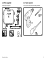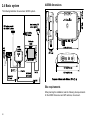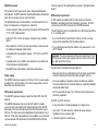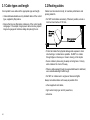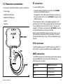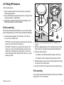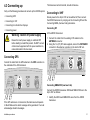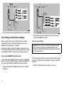
1
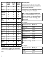
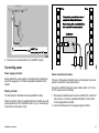
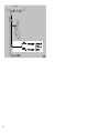
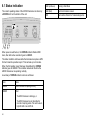
AUTOMATIC IDENTIFICATION SYSTEM
AIS500 Transceiver
Installation instructions
Trademarks and registered trademarks
Autohelm, HSB, RayTech Navigator, Sail Pilot, SeaTalk and Sportpilot are UK registered trademarks of Raymarine UK Limited.
Pathfinder and Raymarine are UK registered trademarks of Raymarine Holdings Limited. 45STV, 60STV, AST, Autoadapt, Auto GST,
AutoSeastate, AutoTrim, Bidata, G Series, HDFI, LifeTag, Marine Intelligence, Maxiview, On Board, Raychart, Raynav, Raypilot, RayTalk,
Raystar, ST40, ST60+, Seaclutter, Smart Route, Tridata, UniControl and Waypoint Navigation are trademarks of Raymarine UK Limited.
All other product names are trademarks or registered trademarks of their respective owners.
Copyright ©2008 Raymarine UK Ltd. All rights reserved.
ENGLISH
Document number: 87112-1
Date: November 2008
Contents
Chapter 1 Introduction ............................................. 7
Chapter 5 Post installation procedures.................. 35
Applicability .................................................................... 7
Safety information........................................................... 7
General information ........................................................ 8
Requirements for USA & Canada .................................... 9
Requirements for areas outside of USA & Canada............ 11
System information ......................................................... 13
5.1 Switching on ............................................................. 36
5.2 Configuration ............................................................ 36
5.3 Checking for interference........................................... 37
5.4 Using AIS ................................................................. 38
Chapter 2 Planning the installation ........................ 17
2.1 EMC installation guidelines ........................................ 18
2.2 Parts supplied........................................................... 19
2.3 Tools required ........................................................... 19
2.4 Basic system ............................................................ 20
Chapter 6 Diagnostics.............................................. 39
6.1 Status indication ....................................................... 40
6.2 Troubleshooting ........................................................ 41
Chapter 7 Specifications.......................................... 43
7.1 General .................................................................... 44
7.2 Transceiver............................................................... 44
7.3 GPS Receiver........................................................... 45
Chapter 3 Cables & connections ............................ 23
3.1 Cable types and length .............................................. 24
3.2 Routing cables .......................................................... 24
3.3 Transceiver connections ............................................ 25
3.4 Cable shielding ......................................................... 26
Chapter 4 Installation procedures .......................... 27
4.1 Fitting transceiver...................................................... 28
4.2 Fitting GPS antenna .................................................. 29
4.3 Connecting up .......................................................... 31
5
6
Chapter 1: Introduction
Applicability
The information in this book applies to all geographical areas unless
otherwise stated.
Safety information
Warning: Product installation
This equipment must be installed in accordance with
the Raymarine instructions provided. Failure to do so
could result in poor product performance, personal
injury, and/or damage to the vessel.
This product is intended only as an aid to navigation
and must never be used in preference to sound
navigational judgment. Only official government
charts and notices to mariners contain all the current
information needed for safe navigation, and the
captain is responsible for their prudent use. It is the
user’s responsibility to use official government charts,
notices to mariners, caution and proper navigational
skill when operating this or any other Raymarine
product.
Caution: Power supply protection
When installing this product ensure the power
source is adequately protected by means of a
suitably-rated fuse or automatic circuit breaker.
Warning: Switch off power supply
Safety Notice
Ensure the boat’s power supply is switched OFF
before starting to install this product. Do NOT connect
or disconnect equipment with the power switched on,
unless instructed in this document.
RF radiation statement
Warning: Potential ignition source
This product is NOT approved for use in
hazardous/flammable atmospheres. Do NOT install in
a hazardous/flammable atmosphere (such as in an
engine room or near fuel tanks).
Introduction
Warning: Ensure safe navigation
Your Raymarine AIS500 transceiver generates and radiates radio
frequency (RF) electromagnetic energy (EME).
Safe Compass Distance
Safe Compass Distance is 1 meter minimum for any compass.
Some compass types may require greater distances. To be sure,
you should locate your transceiver as far as possible from the
compass. Test your compass to verify proper operation while the
transceiver is also operating.
7
General information
Warranty registration
Intended Use
To register your AIS500 transceiver ownership, please take a few
minutes to fill out the warranty registration card found in the box, or
visit www.raymarine.com and register on-line.
Raymarine AIS500 is an AIS Class B transceiver, and is intended
for world wide use aboard leisure marine boats and workboats not
covered by International Maritime Organization (IMO) and Safety of
Life at Sea (SOLAS) Carriage Regulations.
Caution: Cleaning
When cleaning this product do NOT use acid,
ammonia-based or abrasive products, and do NOT
use high pressure washing (jet wash) equipment.
Product disposal
Dispose of this product in accordance with the WEEE Directive.
It is important that you register your product to receive full warranty
benefits. Your unit package includes a bar code label indicating the
serial number of the unit. You should stick this label to the warranty
registration card.
Technical accuracy
To the best of our knowledge, the information in this document was
correct at the time it was produced. However, Raymarine cannot
accept liability for any inaccuracies or omissions it may contain. In
addition, our policy of continuous product improvement may change
specifications without notice. As a result, Raymarine cannot accept
liability for any differences between the product and this document.
AIS500 installation guide
Information scope
The Waste Electrical and Electronic Equipment (WEEE)
Directive requires the recycling of waste electrical and electronic
equipment. Whilst the WEEE Directive does not apply to some
Raymarine products, we support its policy and ask you to be aware
of how to dispose of this product.
AIS disclaimer
All information presented by the Raymarine AIS transceiver is
advisory only, as there is a risk of incomplete and erroneous
information. By placing the AIS500 into service you acknowledge
this and assume complete responsibility for any risks associated
with this device, and accordingly release Raymarine and SRT
Marine Technology Ltd from any and all claims arising from the use
of the AIS service.
8
This document gives introductory, installation and troubleshooting
information for the Raymarine Automatic Identification System Type
500 Transceiver (AIS500) transceiver.
Refer to the ProAIS User Manual and the operating manual for
your Raymarine Multi-Function Display, for instructions on how to
configure and operate your AIS system.
All documents are available to download as PDFs from
www.raymarine.com
Static data requirement
The AIS500 transceiver needs to be correctly programmed with the
following vessel data (static data) before use:
• Vessel Maritime Mobile Service Identity (MMSI) number
• Vessel name
• Vessel call sign
• Vessel dimensions including AIS GPS antenna location
• Vessel type
A MMSI number comprises 9 digits, and a full, valid 9 digit value
must be entered in order to be accepted during setup. Any number
that does not meet these criteria will not be accepted by the system.
All other fields (i.e. vessel type, name etc.) are optional.
Raymarine AIS transceivers comply with the Federal
Communications Commission (FCC) and Industry Canada
requirements that regulate marine AIS and VHF radio usage for the
US and Canada, respectively. Marine AIS users in the US must
comply with all applicable FCC rules and regulations, some of which
are described in this handbook. This information was current at the
time this handbook was printed. Up-to date information, including
licensing requirements, can be obtained on the FCC website at:
www.fcc.gov/wtb/marine
Official FCC forms can be obtained on the FCC website at:
www.fcc.gov/formpage.html
If your vessel already has an MMSI number (used for a VHF DSC
radio) then the same MMSI number must be used to program the
transceiver.
FCC Notice
If a valid MMSI number is not entered, the AIS500 will enter Silent
Mode and will not transmit. However, it will still operate as a receiver.
This device complies with part 15 of the FCC Rules. Operation is
subject to the following two conditions:
Important: In the United States of America, the MMSI and
Static Data must be entered only by a Raymarine dealer or
other appropriately qualified installer of marine communications
equipment on board vessels.The user is NOT authorized to do
this.
Compliance statement
1. This device may not cause harmful interference, and
2. This device must accept any interference received, including
interference that may cause undesired operation.
In Europe and other parts of the world outside of the United States
of America, the MMSI and Static Data can be set up by the user.
Changes or modifications to this equipment not expressly approved
in writing by Raymarine Incorporated could violate compliance
with FCC rules and void the operator’s authority to operate the
equipment.
For further details, refer to the requirements for the area in which
you are operating .
Station Licence
FCC station license requirement
Requirements for USA & Canada
Important information
AIS500 conforms to the relevant FCC requirements
Introduction
An FCC Ship Radio Station License and Call Sign are not required
for most recreational vessels travelling in US waters. However, you
must obtain a license if your vessel travels to foreign ports.
Ships that use MF/HF single side-band radio, satellite
communications, or telegraphy must be licensed by the FCC. You
9
can obtain a Station License by filing FCC Form 605, which is
available from the FCC website listed above.
• Output Power: 2 Watts
Operator License
• Frequency Range: 156.025 to 162.025 MHz
• Modulation: GMSK
FCC operator license requirement
An Operator License is not required to operate a Class B AIS
Transceiver within US territorial waters. However, a license is
required to operate the transceiver if you dock in a foreign port
(including Canada and Mexico) or leave a foreign port to dock in a
US. port. You can request a Restricted Radiotelephone Operator
Permit from the FCC by filing Form 753.
Industry Canada
Industry Canada license requirement
You do not need a license to operate this transceiver within
sovereign waters of Canada or the US. You will need a license to
operate this radio outside of Canada or the US. To obtain Industry
Canada licensing information, contact the nearest field or regional
office, or write:
Industry Canada Radio Regulatory Branch
Attention: DOSP
300 Slater Street
Ottawa, Ontario
Canada, KIA OC8
The following information about the radio is required to complete the
license application:
• Industry Canada Certification Number: 4069B-AIS500
• FCC Type Number: PJ5–AIS500
• FCC Type Accepted: Parts 15 and 80
10
Maritime Mobile Service Identity (MMSI)
A nine-digit Maritime Mobile Service Identity (MMSI) number is
required to operate the AIS500 transceiver.
Note: You can request an MMSI number from the FCC when
you apply for a Station License. If your vessel does not require
a license, you may obtain an MMSI by contacting BoatUS
(www.boatus.com). Once obtained, you can program the MMSI
number into your AIS500 as described in the documentation
accompanying the transceiver.
Programming the MMSI & static data
Important: In the United States of America, it is a violation of the
rules of the Federal Communications Commission to input an
MMSI that has not been properly assigned to the end user or to
otherwise input any inaccurate data in this device. The MMSI
and Static Data must be entered only by a Raymarine dealer or
other appropriately qualified installer of marine communications
equipment on board vessels. Instructions for entering the MMSI
and static data are given in the documentation on the CDROM
supplied with the AIS500 transceiver.
Once static data has been programmed, you must not change
it. If the information programmed is no longer correct, contact
the Raymarine help desk or the dealer or retailer from whom you
purchased the transceiver, to arrange reprogramming.
Antenna Mounting & EME Exposure
This system has a Maximum Permissible Exposure (MPE) Radius of
1.5 meters (per OET Bulletin 65), assuming the maximum power of
the radio and antennas with a maximum gain of 3 dBi. Accounting
for the height of an average adult (2 meters) the minimum height
of the antenna above the deck to meet RF exposure compliance
requirements is 3.5 meters. Do not operate the transceiver when
anyone is within the MPE radius of the antenna, unless shielded
from the antenna field by a grounded metallic barrier.
Warning: Maximum Permissible
Exposure
Maritime Mobile Service Identity (MMSI)
A nine-digit Maritime Mobile Service Identity (MMSI) number is
required to operate the AIS500 Transceiver. In some areas, a radio
operator licence is required before an MMSI number will be issued.
You can request an MMSI number from same agency that issues
radio or Ship Radio licences in your area. Once obtained, you can
program the MMSI number into your AIS500 as described in the
documentation on the CDROM supplied with the AIS500 transceiver.
Failure to observe these guidelines may expose those
within the maximum permissible exposure (MPE)
radius to RF radiation absorption that exceeds the
FCC MPE limit. It is the radio operator’s responsibility
to ensure that no one comes within this radius.
Antenna Mounting & EME Exposure
For optimal radio performance and minimal human
exposure to radio frequency electromagnetic energy,
make sure the antenna is:
• properly mounted
• connected to the radio before transmitting
• located at least 1.5 metres (5 feet) from the radio’s main unit
• located where it will be away from people
List of Countries
• located at least 1.5 meters (5 feet) from the radio’s
main unit
Introduction
Requirements for areas outside of USA
& Canada
For optimal radio performance and minimal human exposure to
radio frequency electromagnetic energy, make sure the antenna is:
• connected to the radio before transmitting
• located where it will be away from people
In Europe, the AIS500 transceiver may be used in the following
countries:
Austria
Liechtenstein
Belgium
Lithuania
Bulgaria
Luxembourg
Croatia
Macedonia, former Yugoslav Republic of
Cyprus
Malta
11
Netherlands
Denmark
Norway
Estonia
Poland
Finland
Portugal
France
Romania
Germany
Slovakia
Greece
Slovenia
Hungary
Spain
Iceland
Sweden
Ireland
Switzerland
Italy
Turkey
Latvia
United Kingdom
Declaration of Conformity
D11639-1
Czech Republic
12
System information
Warning: AIS limitation
Never assume that your AIS is detecting all vessels
in the area. Always exercise due prudence and do
not use AIS as a substitute for sound navigational
judgement.
Overview
The AIS500 uses digital radio signals to exchange ’real-time’
information between vessels and shore based stations on dedicated
VHF frequencies. This information is used to identify and track
vessels in the surrounding area and to provide fast, automatic and
accurate collision avoidance data.
Although AIS augments your radar application by operating in radar
blind spots and detecting smaller AIS-fitted vessels, it does not
replace radar, as it relies on receiving transmitted AIS information
and therefore cannot detect objects such as landmasses and
navigational beacons.
NEVER assume that AIS is displaying information from all vessels
in the area, because:
• Not all vessels are fitted with AIS
• Although it is mandatory for larger commercial vessels to carry
AIS, it is not mandatory to use it.
AIS should be used only to augment radar information, not substitute
it.
Classes of AIS
Your AIS500 is a transceiver that receives messages from and
transmits messages to vessels carrying Class A or Class B
transceivers.
Introduction
Class A Transceivers
Class A AIS transceivers transmit and receive AIS signals. AIS
transceivers are currently mandatory on all commercial vessels
exceeding 300 tons that travel internationally (SOLAS vessels).
The following information can be transmitted by a Class A AIS
system:
• Static data. Includes information such as vessel name, vessel
type, MMSI number, call sign, IMO number, length, beam and
GPS antenna location.
• Voyage related data. Includes information such as draft, cargo,
destination, ETA and other relevant information.
• Dynamic data. Includes information such as time (UTC), ship’s
position, COG, SOG, heading, rate of turn and navigational status.
• Dynamic reports. Ship’s speed and status.
• Messages. Alarms and safety messages.
Remember that not all vessels will transmit all of the information.
Class B Transceivers
Class B AIS transceivers transmit and receive AIS signals, but use
a reduced set of data compared to Class A (see Data Summary). A
Class B AIS transceiver can be fitted on any vessel not fitted with a
Class A transceiver, but is not mandatory aboard any vessel.
Your AIS500 transceiver is a Class B transceiver.
Data Summary
Class A
(receive)
Class B
(send)
Class B
(receive)
Ship’s name
Yes
Yes
Yes
Type
Yes
Yes
Yes
Data
13
Data reporting intervals
Class A
(receive)
Class B
(send)
Class B
(receive)
Call sign
Yes
Yes
Yes
AIS information is classed as either static or dynamic. Static
information is broadcast, when data has been amended, or upon
request, or by default, every 6 minutes.
IMO number
Yes
No
No
The reporting rates for dynamic information depend on speed and
course change, and are given in the following tables.
Length and beam
Yes
Yes
Yes
Antenna location
Yes
Yes
Yes
Draft
Yes
No
No
Cargo
Information
Yes
Yes
Yes
Destination
Yes
No
No
ETA
Yes
No
No
Ships Dynamic Conditions
Reporting rate
Time
Yes
Yes
Yes
At anchor or moored
3 Minutes
Ship’s position
Yes
Yes
Yes
0-14 knots
10 Seconds
COG
Yes
Yes
Yes
0-14 knots and changing course
31/3 Seconds
SOG
Yes
Yes
Yes
14-23 knots
6 Seconds
Gyro heading
Yes
Yes*
Yes
14-23 knots and changing course
2 seconds
Rate of turn
Yes
No
No
Faster than 23 knots
2 seconds
Navigational
status
Yes
No
No
Faster than 23 knots and changing
course
2 seconds
Safety message
Yes
No
Yes
Data
*Class B transceivers do not transmit a Gyro heading unless the
transceiver is receiving an NMEA HDT sentence from an external
source.
14
Note: The reporting rates shown here are for reference and
may not be the rate at which information is actually received
by an AIS500 Transceiver. This is dependent on a number of
factors, including but not limited to antenna height, gain and
signal interference.
Class A systems
Class B systems
Ships Dynamic Conditions
Reporting rate
0 to 2 knots
3 Minutes
Above 2 knots
30 Seconds
Other AIS sources
Source
Reporting rate
Search and Rescue (SAR) aircraft
10 seconds
Aids to navigation
3 minutes
AIS base station
10 seconds or 3.33 seconds,
depending on operating parameters
Introduction
15
16
Chapter 2: Planning the installation
Chapter contents
•
2.1 EMC installation guidelines on page 18
•
2.2 Parts supplied on page 19
•
2.3 Tools required on page 19
•
2.4 Basic system on page 20
Planning the installation
17
2.1 EMC installation guidelines
Raymarine equipment and accessories conform to the appropriate
Electromagnetic Compatibility (EMC) regulations, to minimize
electromagnetic interference between equipment and minimize the
effect such interference could have on the performance of your
system
Correct installation is required to ensure that EMC performance is
not compromised.
For optimum EMC performance we recommend that wherever
possible:
• Raymarine equipment and cables connected to it are:
– At least 1 m (3 ft) from any equipment transmitting or cables
carrying radio signals e.g. VHF radios, cables and antennas.
In the case of SSB radios, the distance should be increased
to 7 ft (2 m).
– More than 2 m (7 ft) from the path of a radar beam. A radar
beam can normally be assumed to spread 20 degrees above
and below the radiating element.
• The product is supplied from a separate battery from that used
for engine start. This is important to prevent erratic behavior
and data loss which can occur if the engine start does not have
a separate battery.
• Raymarine specified cables are used.
• Cables are not cut or extended, unless doing so is detailed in
the installation manual.
Note: Where constraints on the installation prevent any of
the above recommendations, always ensure the maximum
possible separation between different items of electrical
equipment, to provide the best conditions for EMC performance
throughout the installation
18
Suppression ferrites
Raymarine cables may be fitted with suppression ferrites. These
are important for correct EMC performance. If a ferrite has to be
removed for any purpose (e.g. installation or maintenance), it must
be replaced in the original position before the product is used.
Use only ferrites of the correct type, supplied by Raymarine
authorized dealers.
Connections to other equipment
Requirement for ferrites on non-Raymarine cables
If your Raymarine equipment is to be connected to other equipment
using a cable not supplied by Raymarine, a suppression ferrite
MUST always be attached to the cable near the Raymarine unit.
2.2 Parts supplied
2.3 Tools required
Check all parts are present.
Ensure you have these tools before starting installation.
AIS500Transceiver
GPS Antenna
1/4" (3.2mm)
Drill bit
Thumb
nuts (x 2)
AIS
500
Mounting
studs (x 2)
Drill
No 8 Screws (x 4)
3.2 ft (1. m)AIS to VHF
Antenna connector cable
AUTOMATIC IDENTIFI
CATION SYSTEM
AIS500 Transceiver
Installation instructions
Planning the installation
Warranty document
CDROM
D11623-1
Installation instructions
Phillips
screwdriver
D11630-1
19
2.4 Basic system
7.37 in (187.2 mm)
The following illustration shows a basic AIS500 system.
Boat’s existing GPS
antenna (typical)
GPS antenna supplied
withAIS500Tranceiver
Boat’s existing
VHF antenna
AIS
500
1.65 in
3.46 in
(88 mm) (41.8 mm)
AIS500 dimensions
Multifunction
display
AIS500
Transceiver
VHF
radio
9.96 in (252.9 mm)
PAGE
ACTIV
E
WPTS
MOB
DATA
2.43 in
(61.7 mm)
MENU
OUT
RANGE
IN
AIS
500
RF
OK
SeaTalkng
NMEA0183
(4.8 baud)
0
9.51 in (241.6 mm)
Power in
NMEA0183
(38.4 baud)
SeaTalk
RS232
10.76 in (273.3 mm)
D11625-1
0
CANCEL
Compass minimum safe distance: 39 in (1 m)
Site requirements
When planning the installation, take the following site requirements
for the AIS500 transceiver and GPS antenna, into account.
20
AIS500 transceiver
This product is NOT approved for use in hazardous/flammable
atmospheres. Do NOT install in a hazardous/flammable atmosphere
(such as in an engine room or near fuel tanks).
The loss values for the inbuilt splitter are given in the Specification
section.
GPS antenna requirement
The AIS500 transceiver must be fitted in a location where it is not
likely to be stepped on or tripped over, and which:
A GPS antenna is supplied with the transceiver and must be
installed in accordance with the instructions given here. Do NOT
connect any other GPS antenna to the AIS500 transceiver.
• Is close enough to allow connection to the boat’s VHF set with the
3 ft (1 m) RF cable supplied.
The GPS antenna can be mounted either on a flat horizontal surface
or on a suitable pole.
• Is at least 3 ft (1 m) from an engine, compass or any magnetic
device.
• If you intend surface mounting the antenna, ensure you have
access to the underside of the mounting surface.
• Has at least 6 in (100 mm) of clear space below, to allow access
for cabling and adequate cable bends.
• If you intend pole-mounting the antenna, the pole needs a 1 inch
14 TPI thread.
• Is maintained at a temperature between –10°C (14°F) and 55°C
(130°F).
• Is maintained in a dry condition and where there is no likelihood
of the transceiver being splashed.
• Does NOT have a flammable or hazardous atmosphere.
Power supply
The AIS500 transceiver requires a 12 V dc or 24 V dc power supply,
typically from a circuit breaker on the boat’s power panel or from a
fuse block near the transceiver.
VHF antenna requirement
The AIS500 transceiver requires inputs from both GPS and VHF
antenna.
The AIS500 transceiver has an inbuilt VHF splitter to enable
you to connect your existing VHF antenna directly to the AIS500
transceiver, then route the split signal from the transceiver to your
VHF set. This may cause some degradation of performance of your
VHF set. If the level of degradation is unacceptable, we recommend
you use separate VHF antennae for the AIS500 and the VHF set.
Planning the installation
Important: The main requirement of the intended location for the
GPS antenna is that it gives a good direct line of site to the entire
sky, right around the horizon.
Ensure that the intended mounting location is:
• Open and clear of any obstructions (such as masts, search lights,
or other structures) that could block line-of-sight to the sky.
• As low as possible, to keep the antenna as stable as possible.
The more stable the unit, the more effectively it will track satellites
and provide stable data.
• As far as possible (at least 1 m (3 ft)) from other antennae and
electronic equipment.
Do NOT mount the antenna:
• In any area where it could be stepped on or tripped over
• Up a mast. This will cause the antenna to swing and give
significant errors in position data
• In the direct path of a radar beam.
21
SeaTalkng requirement
A fitted SeaTalkng connector enables you to connect the AIS500
transceiver to SeaTalkng, aboard vessels on which the multi-function
displays are connected via SeaTalkng.
Before connecting to SeaTalkng, refer to the SeaTalkng Reference
Manual, and ensure that with this product connected, the maximum
permitted Load Equivalence Number (LEN) value for the system will
not be exceeded.
Note that the AIS500 transceiver has a SeaTalkng LEN value of 1.
22
Chapter 3: Cables & connections
Chapter contents
•
3.1 Cable types and length on page 24
•
3.2 Routing cables on page 24
•
3.3 Transceiver connections on page 25
•
3.4 Cable shielding on page 26
Cables & connections
23
3.1 Cable types and length
3.2 Routing cables
It is important to use cables of the appropriate type and length
Cables must be routed correctly, to maximize performance and
prolong cable life.
• Unless otherwise stated use only standard cables of the correct
type, supplied by Raymarine.
• Ensure that any non-Raymarine cables are of the correct quality
and gauge. For example, longer power cable runs may require
larger wire gauges to minimize voltage drop along the run.
• Do NOT bend cables excessively. Wherever possible, ensure a
minimum bend radius of 100 mm.
Minimum bend
200 mm (8 in)
diameter
Minimum bend of cable
100 mm (4 in) radius
• Protect all cables from physical damage and exposure to heat.
Use trunking or conduit where possible. Do NOT run cables
through bilges or doorways, or close to moving or hot objects.
• Secure cables in place using tie-wraps or lacing twine. Coil any
extra cable and tie it out of the way.
• Where a cable passes through an exposed bulkhead or deckhead,
use a suitable watertight feed-through.
• Do NOT run cables near to engines or fluorescent lights.
Always route data cables as far away as possible from:
• other equipment and cables,
• high current carrying ac and dc power lines,
• antennae.
24
3.3 Transceiver connections
RF connections
The transceiver has attached cables to provide connections to:
In a typical AIS500 system:
• The boat’s existing VHF antenna connects to the ANTENNA
connector on the AIS500 transceiver.
• Power supply
• NMEA0183, 4800 baud
• The supplied 1 m RF cable connects the antenna connector on
the boat’s existing VHF set, to the VHF RADIO connector on the
AIS500 transceiver.
• NMEA0183, 38400 baud
• RS232
If this arrangement results in unacceptable degradation of the
performance of the VHF radio, separate antennae should be used
for the AIS500 transceiver and the VHF radio. In this case, the
supplied 1 m RF cable is not used and the VHF RADIO connector
on the AIS500 transceiver remains unconnected.
• SeaTalkng
AIS
500
Note that when the AIS500 transceiver transmits, there is a very
brief interruption to the boat’s VHF receive function. This may
be noticeable during when a long, continuous broadcast is being
received.
AIS500Transceiver
GPS connections
The GPS supplied as part of the AIS500 system has a fitted 10 m
(33 ft) cable to connect to the AIS500 transceiver GPS connector.
Power
NMEA connections
The AIS500 transceiver has a fitted cable which provides prepared,
bare-wire NMEA0183 connections at both 4800 baud and
38400 baud rates, as follows:
NMEA0183
ng
SeaTalk
D11640-1
Cables & connections
Wire color
NMEA0183 Function
Green
4800 baud receive -
White
4800 baud receive +
Brown
4800 baud transmit 25
Wire color
NMEA0183 Function
Yellow
4800 baud transmit +
Orange with green stripe
38400 baud receive -
Orange with white stripe
38400 baud receive +
Orange with brown stripe
38400 baud transmit -
Orange with yellow stripe
38400 baud transmit +
A multiplexer built into the transceiver manages both 4800 and
38400 baud rates. This feature effectively frees up an NMEA port
on your multi-function display (MFD). if only one NMEA0183 port
exists on your equipment, the multiplexer eliminates the need for a
separate multiplexer.
Typically the NMEA0183 connections are used as follows:
• The 4800 baud wires connect to the appropriate points on the
VHF radio or other NMEA0183 4800 baud input/output device.
• The 38400 baud wires connect to appropriate Raymarine MFDs.
The NMEA0183 port on each MFD connected in this manner
must be set to 38400 baud.
26
3.4 Cable shielding
Ensure that all data cables are properly shielded that the cable
shielding is intact (e.g. hasn’t been scraped off by being squeezed
through a tight area).
Chapter 4: Installation procedures
Chapter contents
•
4.1 Fitting transceiver on page 28
•
4.2 Fitting GPS antenna on page 29
•
4.3 Connecting up on page 31
Installation procedures
27
4.1 Fitting transceiver
Ensure that the intended installation site meets the conditions
described under Site requirements, mark and drill the mounting
holes, then fit the transceiver as shown in the following illustrations.
Note: This procedure shows how to mount the transceiver
vertically, which is the recommended method. However, you may
mount it horizontally if necessary.
x4
D11633-1
Note: If you are fitting the transceiver to fiberglass that has
a gelcoat surface, overdrill the surface to prevent the gelcoat
from damage when securing the screws. Before drilling the pilot
holes, hand drill the marked locations with an oversized bit and
countersink to approximately 9.5 mm (3/8 in) diameter.
Ver
tica
l
2.
1
2
3
m
6 mmum
ni
mi
3.
28
D11634-1
x4
1.
D11632-1
Ver
tica
l
4.2 Fitting GPS antenna
A
B
1
To fit the GPS antenna:
1. Select a suitable location for the GPS antenna as described
under Site requirements.
2. Fit your GPS antenna using either the Surface mounting or Pole
mounting procedure, as appropriate.
3. Ensuring the conditions in Running cables are fulfilled, run the
GPS antenna cable to the AIS transceiver.
2
3
2
3
Surface mounting
1. Use the template supplied in this handbook to mark the two
6 mm (0.25 in) mounting holes.
• OPTION A: If the cable is going to pass through the mounting
surface drill a 19 mm (0.75 in) center hole.
• OPTION B: If the cable is to be routed from the side of the
receiver (i.e. above the mounting surface), remove the two
plastic tabs (1) obstructing the cable channel. If you do not
remove these tabs before using the cable channel, you could
damage the cable.
4
4
Top view
Underside view
D11638-1
When surface mounting the GPS antenna, you can route the cable
either centrally (Option A) or from the side of the antenna (Option B).
2. Screw the two mounting studs (2) into the underside of the
receiver.
3. Stick the supplied gasket (3) to the mounting surface, ensuring
that the holes on the gasket correspond with the drilled holes.
4. Route the cable as follows:
• For Option A, feed the cable down through the center hole.
• For Option B, route the cable along the cable exit channel.
5. Carefully place the receiver so the mounting studs pass through
the holes in the mounting surface.
6. Secure the receiver to the surface using the two thumb nuts (4).
Pole mounting
If you want to pole-mount the GPS antenna, obtain a pole of suitable
length with a 1 inch 14 TPI thread.
Installation procedures
29
5. Ensuring you do not trap the cable, place the GPS antenna on
the pole mount adaptor so the screw holes align, then secure the
antenna with the 2 screws retained at step 2.
Antenna
A
B
D11642-1
Pole mount adaptor
1. Ensuring that the Site requirements are met, securely attach the
pole to a suitable, secure point.
2. Remove and retain the screws securing the GPS antenna from
the pole mount adaptor, then separate these two items.
3. Screw the pole mount adaptor fully onto the pole and ensure
it is secure on the pole.
4. Route the antenna cable as follows:
i. If you want to route the antenna cable directly down from
the antenna (option A), feed it through the center of the pole
mount adaptor and then down through the pole.
ii. If you want to route the antenna cable out of the side of the
antenna (option B), remove the two plastic tabs from the
cable channel, then feed the cable along the channel.
30
4.3 Connecting up
The transceiver will not transmit, but will still receive.
Carry out the following procedures to connect up the AIS500 system:
Connecting to VHF
• Connecting GPS
Ensure power to the ship’s VHF set is switched off, then connect
the AIS500 transceiver by carrying out the Connecting RF and the
Connecting NMEA (low baud rate) procedures.
• Connecting to VHF
• Connecting to multi-function displays
Connecting RF
• Connecting power
Warning: Switch off power supply
Ensure the boat’s power supply is switched OFF
before starting to install this product. Do NOT connect
or disconnect equipment with the power switched on,
unless instructed in this document.
At the AIS500 transceiver:
1. Connect the cable from the existing VHF antenna to the
ANTENNA connector.
2. Using the 1 m (3 ft) RF cable supplied, connect the VHF RADIO
connector to the antenna connector on the boat’s VHF set.
S TATUS
TA
Connecting GPS
POWER D ATA
AT
GPS
VHF RADIO
ANTENNA
Connect the cable from the GPS antenna to the GPS connector on
the underside of the AIS transceiver.
S TATUS
TA
POWER D ATA
AT
D11645-1
GPS
VHF RADIO
ANTENNA
Connecting NMEA0183 (low baud rate)
D11643-1
If the GPS antenna is not connected, the transceiver will operate
in Silent Mode and an alarm message will be generated. You must
acknowledge all alarm messages.
Installation procedures
Connect the AIS500 transceiver 4800 baud NMEA0183 bus to the
ship’s VHF as follows:
1. Identify the 4800 baud NMEA0183 wires from the AIS500
transceiver.
31
Transceiver
Green
White
Receive
Receive
Brown
Transmit
Yellow Transmit
NMEA0183
4800 baud
Connect to
boat's VHF
Orange & green
Orange & white
Receive
Receive
Orange & brown
Transmit
Orange & yellow
Transmit
NMEA0183
38400 baud
Connect to
MFD
D11646-1
2. Connect these wires to the appropriate points on the ships VHF.
Connecting to multi-function displays
Data is transferred between the AIS500 transceiver and the
associated Raymarine multi-function display(s) using either
NMEA0183 (at 38400 baud) or SeaTalkng.
Ensure power to the multi-function displays is switched off, then
connect the AIS500 transceiver by carrying out either the Connect
using NMEA0183 OR the Connect using SeaTalkng procedure.
D11647-1
2. Connect these wires to the appropriate points on the boat’s
38400 baud, NMEA0183 system.
Connect using SeaTalkng
Important: Do not connect to a Raymarine SeaTalkng system,
if this will cause the maximum permitted SeaTalkng Load
Equivalence Number (LEN) value for the system to be exceeded
(see Site Requirements).
Connect using NMEA0183 (high baud rate)
If your multi-function displays are NOT connected to a SeaTalkng
system, connect the AIS500 transceiver 38400 baud, NMEA0183
bus to the boat’s 38400 baud, NMEA0183 system as follows:
1. Identify the 38400 baud, NMEA0183 wires from the AIS500
transceiver.
32
If your multi-function displays are connected to a SeaTalkng system,
connect the AIS500 transceiver SeaTalkng connector to SeaTalkng
as follows:
1. Identify the AIS500 transceiver SeaTalkng connector.
+VE bar
-VE bar
Where possible, connect individual items of
equipment to individual circuit breakers.
Where this not possible, use individual in-line
fuses to provide the necessary protection.
Circuit breaker
SeaTalkng spur
Connect to boat's SeaT
alkng system
D11648-1
system.
Fuse
Fuse
D11637-1
2. Connect to a convenient point on the
SeaTalkng
Connecting power
Power supply protection
Power connection procedure
Always protect the power supply by connecting the red (positive)
wire to the supply via a 5 A fuse or equivalent automatic circuit
breaker.
The use of crimped and soldered lugs is recommended, to provide
optimum connection to the power source.
Sharing a breaker
The text within the illustration has been updated for clarity
Where more than 1 piece of equipment shares a breaker you must
provide protection for the individual circuits. E.g. by connecting an
in-line fuse for each power circuit.
Installation procedures
Connect the AIS500 transceiver power cable to either a 12 V dc or
24 V dc power source as follows:
1. Ensuring the intended power source is switched off, connect the
red wire via a 5 A fuse or equivalent automatic circuit breaker
to the supply positive terminal.
2. Connect the black wire to the supply negative terminal.
33
Red
Black
Power supply
Power supply
Connect to
12 V dc, or
24 V dc
D11649-1
34
Chapter 5: Post installation procedures
Chapter contents
•
5.1 Switching on on page 36
•
5.2 Configuration on page 36
•
5.3 Checking for interference on page 37
•
5.4 Using AIS on page 38
Post installation procedures
35
5.1 Switching on
5.2 Configuration
When the installation is complete, observe the STATUS indicator
and:
1. Switch on power to the AIS500 transceiver.
2. Check that:
i. When power is first applied, the STATUS indicator flashes
RED twice, then after a few seconds shows AMBER.
ii. After a time (up to 2 minutes) the indicator changes to green.
This indicates the AIS500 transceiver is operating normally.
Warning: Configure before use
This Raymarine product must be correctly configured,
to ensure optimum performance and minimize the
chances of unsafe or other erroneous data.
Configuration requirement
After installation and successful switch on, the AIS500 transceiver
must be configured for optimum performance aboard the vessel.
The person configuring the AIS500 needs to know the following
vessel information:
• MMSI number
• Name
• Call sign
• Dimensions
• Type
• GPS antenna position
The manner in which configuration is carried out depends on the
legal requirements of the geographical area you are.
Important: Before starting any AIS configuration procedure,
SWITCH OFF all associated multi-function displays (MFDs),
otherwise you will not be able to correctly configure your AIS500
transceiver.
USA
In the USA, it is a legal requirement that the configuration is
performed by a suitable dealer.
36
You can use the supplied ProAIS PC software, to check the vessel
data programmed into your AIS500. If this information is incorrect
please contact your Raymarine dealer before using the transceiver.
5.3 Checking for interference
Areas outside of USA
If you have installed any system aboard a boat or made other
changes to the boat’s electronic systems (radar, VHF radio etc.),
you need to check before casting off, that all electrical systems
operate satisfactorily without any undue electrical interference,
in order to conform with Electro Magnetic Compatibility (EMC)
regulations. To do this:
In areas outside of the USA, use the supplied ProAIS PC software to
configure your AIS500 transceiver, as described in the instructions
provided in the ProAIS User Guide.
Post installation check
1. Ensuring it is safe to do so, turn on all electronic systems aboard
the boat.
2. Check that the electronic systems all operate satisfactorily.
Post installation procedures
37
5.4 Using AIS
The exact method of using AIS depends on which type of Raymarine
multi-function display (MFD) you are using.
Refer to the handbook for your MFD for information on using AIS.
38
Chapter 6: Diagnostics
Chapter contents
•
6.1 Status indication on page 40
•
6.2 Troubleshooting on page 41
Diagnostics
39
6.1 Status indication
The current operating status of the AIS500 transceiver is shown by
a STATUS LED on the bottom of the unit.
S TATUS
POWER D ATA
AT
GPS
VHF RADIO
ANTENNA
When power is switched on, the STATUS indicator flashes RED
twice, then after a few seconds it goes to AMBER.
The amber condition continues while the transceiver acquires a GPS
fix then transmits a position report. This can take up to 2 minutes.
When the first position report has been transmitted, the STATUS
indicator goes to GREEN. This condition remains all the time the
AIS500 transceiver is operating normally
A summary of STATUS indicator colors is as follows:
Color
Status
GREEN
AIS500 transceiver is operating normally
AMBER
Either:
• The AIS500 transceiver is starting up, or
• The AIS500 transceiver has not transmitted for
more than 2 reporting periods. This could be due to
high AIS traffic or loss of GPS fix.
40
BLUE (continuous)
Running in Silent Mode
BLUE (flash)
Each time AIS data is received
RED
Fault condition. Refer to the Troubleshooting section
6.2 Troubleshooting
Status indicator
remains amber
Issue
Action
Wait at least 30 minutes to check that a ’Quiet time’ has
not been requested by the local authority
Check that the:
No power
Check:
• GPS antenna is properly connected
• All power connections
• GPS antenna has a clear view of the sky, without any
obstructions
• Check relevant fuses
• MMSI number has been properly configured (use the
proAIS application)
• That power supply is at the correct voltage (12 V or 24 V)
AIS configuration
data is not saved
Switch off all associated multi-function displays (MFDs),
then re-configure
No data
Check that:
• The VHF antenna is properly connected and in particular
it is not short circuiting to the vessel structure
• Connections are secure throughout the system
• That power supply is at the correct voltage (12 V or 24 V)
• The VHF aerial lead is securely connected and that you
can send and receive VHF radio information
• The MMSI number has been properly configured (use
the proAIS application)
No vessel data
Status indicator is
red
Check that:
At the relevant Raymarine multi function display:
• Place the cursor over the targeted vessel and ensure
the AIS DATA soft key is not set to OFF
• Ensure the AIS layer is set to ON
• Ensure displayed target types are set to ALL
No AIS data
Check the NMEA output from the multi-function displays to
the AIS500 input, and ensure:
• The wires are correctly connected
• The baud rate is 38400 baud
Diagnostics
41
42
Chapter 7: Specifications
Chapter contents
•
7.1 General on page 44
•
7.2 Transceiver on page 44
•
7.3 GPS Receiver on page 45
Specifications
43
7.2 Transceiver
7.1 General
Waterproofing
IPX2
Operating frequency range
156.025 MHz to 162.025 MHz
Operating temperature
range
-10ºC to +55º C (14ºF to 131ºF)
Channel spacing
25 kHz
Receivers
2 receivers
Storage temperature
range
-20ºC to +75º C (-4ºF to 167ºF)
Receiver sensitivity
<-107 dBm
Humidity
Up to 95% at 35º non-condensing
Transmitter
1 transmitter
Power supply voltage
12 V to 24 V dc, reverse polarity protected
Transmitter output power
2 W (33 dBm)
Supply current at 12 V dc
Nominal: 0.62 A
Peak (during transmit): 2.1 A
Transceiver standard
Class B ’CS’ AIS to IEC62287-1
Size
273.3 mm x 187.2 mm x 61.7 mm (10.76 in x 7.37 in
x 2.43 in)
Weight
1.19 kg (2.63 lb)
Mounting
Four keyholed mounting tabs and mounting screws
Connectors
VHF antenna – SO-239
VHF In – BNC
GPS In – TNC
PC RS232 – 9 Way D Type
NMEA0183 HS – stripped wires
NMEA0183 LS – stripped wires
Power – stripped wires
SeaTalkng - proprietary Raymarine connector
NMEA sentences
!AIVDO, !AIVDM, !AIALR, and !AITXT
• With NMEA GPS
output ON
$GPGLL, $GPGGA, $GPVTG, $GPGSV, $GPGSA,
$GPZDA, $GPRMC, and $GPGBS
VHF splitter losses
Receive: less than 4 dB
Transmit: less than 1 dB
44
7.3 GPS Receiver
Receiver channels
16
Receiver sensitivity
Acquisition -140 dBm
Tracking -150 dBm
Nominal Time to First Fix
34 seconds
Specifications
45
46
www.raymarine.com