1
R
EN
TME-M710
6.5-INCH WIDE LCD MONITOR
• OWNER'S MANUAL
Please read before using this equipment.
• MODE D'EMPLOI
Veuillez lire avant d’utiliser cet appareil.
FR
• MANUAL DE OPERACIÓN
Léalo antes de utilizar este equipo.
ES
ALPINE ELECTRONICS MARKETING, INC.
1-1-8 Nishi Gotanda,
Shinagawa-ku, Tokyo 141-0031, Japan
Phone 03-5496-8231
ALPINE ELECTRONICS OF AUSTRALIA PTY. LTD.
161-165 Princes Highway, Hallam
Victoria 3803, Australia
Phone 03-8787-1200
ALPINE ELECTRONICS OF AMERICA, INC.
19145 Gramercy Place, Torrance,
California 90501, U.S.A.
Phone 1-800-ALPINE-1 (1-800-257-4631)
ALPINE ELECTRONICS GmbH
Frankfurter Ring 117, 80807 München,
Germany
Phone 089-32 42 640
ALPINE ELECTRONICS OF CANADA, INC.
777 Supertest Road, Toronto, Ontario M3J 2M9,
Canada
Phone 1-800-ALPINE-1 (1-800-257-4631)
ALPINE ELECTRONICS OF U.K. LTD.
Alpine House
Fletchamstead Highway,
Coventry CV4 9TW, U.K.
Phone 0870-33 33 763
Qingdao Dongli Xinhaiyuan
Printing Co., Ltd.
No.17, jiushuidong road,
Qingdao, China
ALPINE ELECTRONICS FRANCE S.A.R.L.
(RCS PONTOISE B 338 101 280)
98, Rue de la Belle Etoile, Z.I. Paris
Nord II, B.P. 50016, 95945 Roissy
Charles de Gaulle Cedex, France
Phone 01-48638989
ALPINE ITALIA S.p.A.
Viale C. Colombo 8, 20090 Trezzano
Sul Naviglio (MI), Italy
Phone 02-484781
ALPINE ELECTRONICS DE ESPAÑA, S.A.
Portal de Gamarra 36, Pabellón, 32
01013 Vitoria (Alava) - APDO 133, Spain
Phone 945-283588
Designed by ALPINE Japan
Printed in China (S)
68-02278Z73-A
ENGLISH
Contents
Operating Instructions
WARNING
Installation and Connections
Warning ........................................................... 11
Caution ............................................................ 11
WARNING .................................................. 2
CAUTION ................................................... 3
PRECAUTIONS ......................................... 3
Basic Operation
Precautions ...................................................... 12
Installation ...................................................... 13
Connections .................................................... 14
LIMITED WARRANTY
Screen Display ON/OFF .................................... 4
FR
Adjusting the Volume ......................................... 4
Switching the Source ......................................... 4
Switching the Screen Position ........................... 4
Switching the display mode ............................... 5
Adjusting ............................................................ 5
Information
ES
In Case of Difficulty .......................................... 9
Specifications ................................................... 10
DE
IT
SE
1-EN
WARNING
WARNING
This symbol means important instructions.
Failure to heed them can result in serious
injury or death.
DO NOT OPERATE ANY FUNCTION THAT TAKES
YOUR ATTENTION AWAY FROM SAFELY DRIVING
YOUR VEHICLE.
Any function that requires your prolonged attention
should only be performed after coming to a complete stop.
Always stop the vehicle in a safe location before
performing these functions. Failure to do so may result in
an accident.
KEEP THE VOLUME AT A LEVEL WHERE YOU CAN
STILL HEAR OUTSIDE NOISE WHILE DRIVING.
Failure to do so may result in an accident.
MINIMIZE DISPLAY VIEWING WHILE DRIVING.
Viewing the display may distract the driver from looking
ahead of the vehicle and cause an accident.
DO NOT DISASSEMBLE OR ALTER.
Doing so may result in an accident, fire or electric shock.
USE THIS PRODUCT FOR MOBILE 12V APPLICATIONS.
Use for other than its designed application may result in
fire, electric shock or other injury.
KEEP SMALL OBJECTS SUCH AS BATTERY OUT OF
THE REACH OF CHILDREN.
Swallowing them may result in serious injury. If
swallowed, consult a physician immediately.
USE THE CORRECT AMPERE RATING WHEN
REPLACING FUSES.
Failure to do so may result in fire or electric shock.
2-EN
DO NOT WATCH VIDEO WHILE DRIVING.
Watching the video may distract the driver from looking
ahead of the vehicle and cause an accident.
INSTALL THE PRODUCT CORRECTLY SO THAT THE
DRIVER CANNOT WATCH TV/VIDEO UNLESS THE
VEHICLE IS STOPPED AND THE EMERGENCY BRAKE
IS APPLIED.
It is dangerous (and illegal in many states) for the driver to
watch TV/Video while driving a vehicle. Installing this
product incorrectly enables the driver to watch TV/Video
while driving. This may cause a distraction, preventing the
driver from looking ahead, thus causing an accident. The
driver or other people could be severely injured.
CAUTION
This symbol means important instructions.
Failure to heed them can result in injury or
material property damage.
HALT USE IMMEDIATELY IF A PROBLEM APPEARS.
Failure to do so may cause personal injury or damage to
the product. Return it to your authorized Alpine dealer or
the nearest Alpine Service Center for repairing.
PRECAUTIONS
Temperature
Be sure the temperature inside the vehicle is between
+45°C (+113°F) and 0°C (+32°F) before turning your unit
on.
Fuse Replacement
When replacing the fuse(s), the replacement must be of
the same amperage as shown on the fuse holder. If the
fuse(s) blows more than once, carefully check all
electrical connections for shorted circuitry. Also have your
vehicle’s voltage regulator checked.
Maintenance
If you have problems, do not attempt to repair the unit
yourself. Return it to your Alpine dealer or the nearest
Alpine Service Station for servicing.
Installation Location
Make sure the TME-M710 will not be exposed to:
• Direct sun and heat
• High humidity
• Excessive dust
• Excessive vibrations
• After turning the system off, a slight ghost of the image
will remain temporarily. This is an effect peculiar to
LCD technology and is normal.
• Under cold temperature conditions, the screen may
lose contrast temporarily. After a short warm-up
period, it will return to normal.
3-EN
Basic Operation
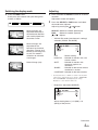
Switching the Screen Position
If the screen is out of position when, for example,
navigation system is connected to the AUX IN 1 or
AUX IN 2 terminal by using the RCA extension cable,
switch the screen position.
1
2
POWER
SELECT
Main power
lamp
DISP
Screen Display ON/OFF
1
2
Press the POWER button.
To turn off the POWER, press the POWER
button again.
•
If properly connected, the monitors main
POWER will turn off when the vehicle's
ignition switch is off. If the main power lamp
illuminates in the STAND BY mode, the
vehicle's battery may be discharged.
After turning the system off, a slight ghost of
the image will remain temporarily. This is an
effect peculiar to LCD technology and is
normal.
Under cold temperature conditions, the
screen may lose contrast temporarily. After a
short warm-up period, it will return to normal.
•
•
Adjusting the Volume
1
Adjust the volume level by pressing the
button.
or
Switching the Source
1
Press the SELECT button.
Each press of the button will cycle through the
modes as follows:
AUX1
4-EN
AUX2
NAV. (NAVIGATION)
Switch the mode to AUX1 or AUX2 to display the
navigation screen.
Press and hold the DISP button for at least 2
seconds.
Press and hold the DISP button again for at least
2 seconds to return the position.
Switching the display mode
Adjusting
1
1
Press the DISP button.
Each press of the button will cycle through the
modes as follows:
WIDE
WIDE
CINEMA
CINEMA
NORMAL
Normal images are
expanded uniformly in
the horizontal direction
and are displayed over
the entire screen.
Normal images are
expanded in the
horizontal and vertical
directions. The top and
bottom of the image are
cut off. This mode is
suited for 16:9 cinema
size images.
Normal image (4:3)
NORMAL
2
Press and hold the SELECT button for at least 2
seconds.
Adjustment screen will appear.
Press the SELECT or DISP button and select
the mode to be adjusted.
Adjust by pressing the
or
button.
SELECT : Selects the mode. (downward)
DISP
: Selects the mode. (upward)
or
: Adjusts.
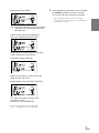
1 VISUAL EQ mode (manufacturer’s settings)
selection (VISUAL EQ MODE)
OFF
NIGHT M.
: Default setting.
: Suitable for movies with a lot
of dark scenes.
SOFT
: Suitable for movies with
computer graphics or
animation.
SHARP
: Suitable for old movies whose
resolution is unclear.
CONTRAST : Suitable for the latest movies.
• Set this function to “OFF” to return to the default
values after changing between modes “NIGHT M.”
and “CONTRAST” and adjusting the image
brightness, color density and so on.
2 Brightness adjustment (BRIGHT)
Allows the brightness (–15 (MIN)~+15
(MAX)) of the picture.
Continued
5-EN
EN
Basic Operation
3 Color depth adjustment (COLOR)
Change depth can be adjusted from –15
(MIN) to +15 (MAX).
* Adjustment cannot be made in the
NAVIGATION (RGB connection) mode.
4 Tint tone adjustment (TINT)
7 Dimmer adjustment (DIMMER)
AUTO : Turning on/off the headlight switches
the screen brightness between
DIMMER HI LEVEL and DIMMER LO
LEVEL.
LOW : The backlighting is set to the value
adjusted at “DIMMER LO LEVEL”.
HIGH : The backlighting is set to the value
adjusted at “DIMMER HI LEVEL”.
8 Dimmer HIGH level adjustment (DIMMER HI
LEVEL)
Tint tone can be adjusted from G15 (G MAX)
to R15 (R MAX).
* Adjustment cannot be made in the
NAVIGATION (RGB connection) mode.
5 Contrast adjustment (CONTRAST)
Adjusts the HIGH LEVEL (16 (MIN) to 31
(MAX)) of the dimmer.
9 Dimmer LOW level adjustment (DIMMER LO
LEVEL)
Contrast can be adjusted from –15 (LOW) to
+15 (HIGH).
6 Screen quality adjustment (SHARP)
Adjusts the LOW LEVEL (0 (MIN) to 15
(MAX)) of the dimmer.
p Change sound output (SOUND OUT)
Screen quality can be adjusted from –15
(SOFT) to +15 (HARD).
* Adjustment cannot be made in the
NAVIGATION (RGB connection) mode.
• If 2 to 6 are adjusted, VISUAL EQ mode in 1
changes to “CUSTOM”.
6-EN
MONITOR
: Outputs sound through the
built-in speakers.
HEADPHONE : Outputs sound to
headphones if connected.
* Note that sound will not be output unless
the audio output settings are appropriate.
q Beep tone setting (BEEP)
3
After completing adjustments, press and hold
the SELECT button for at least 2 seconds.
The screen will return to the normal mode.
• If no operation is made for 10 seconds after
selecting a mode to be adjusted, the adjustment
mode will be cleared.
EN
ON : Beep tone sounds to inform you that the
operation is accepted, when you press
the button etc.
w External input sound level adjustment
(AUX IN-1 LEVEL/AUX IN-2 LEVEL)
HIGH : Sets the sound level at a high level.
LOW : Reduces the sound level.
e Navigation settings (NAV. IN)
When the navigation is connected to the
RGB terminal, set to ON.
r Guide control setting (GUIDE CONTROL)
It is audio interruption setting for the
navigation system.
Be sure to set to “STANDARD”.
•
The setting can be made only when ON is
set in “e Navigation settings (NAV. IN)”.
7-EN
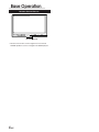
Base Operation
Remote Control Sensor
Remote sensor
• Receives the remote control signal from connected
ALPINE products such as navigation and DVD players.
8-EN
Information
In Case of Difficulty
If you encounter a problem, please review the items in
the following checklist. This guide will help you isolate
the problem if the unit is at fault. Otherwise, make sure
the rest of your system is properly connected or consult
your authorized Alpine dealer.
No function or display.
• Car's ignition is off.
- Turn the ignition on.
• No fuse or blown fuse.
- Check the cause and replace the fuse.
• Incorrect connections.
- Check connection and remedy.
• Vehicle's battery is weak.
- Check the voltage of vehicle's battery.
Navigation screen is not displayed or navigation
system’s remote controller keys do not work.
• Navigation system’s power is turned off.
- Press the ON/OFF (POWER) button on the navigation
system’s remote controller to turn the navigation
system’s power on.
EN
Screen is out of position.
• Navigation system is connected by using the RCA
extension cable.
- Press and hold the DISP button for at least 2 seconds to
switch the screen position.
* The fluorescent tube replacement is not free of charge
even within the warranty period, for the tube is an article
of consumption.
Unclear picture display.
• Fluorescent tube is exhausted.
- Replace the fluorescent tube*.
No picture display.
• Brightness control is set for minimum brightness control.
- Adjust the brightness.
• Incorrect setting of the VCR mode.
- Switch to the correct mode.
• Protective circuit is on because of high temperature.
- Wait until the temperature inside the vehicle comes
down to the operating temperature range (45°C).
• Incorrect or open connection with the Monitor, AV
interface unit.
- Check the connection and remedy.
Picture color is poor.
• Brightness/Color/Tint control are not set to the proper
positions.
- Check each control.
Spots or dotted lines/stripes appear.
• Caused by neon signs, high-voltage power lines, CB
transmitter, other vehicle's ignition plugs, etc.
- Change the location of your vehicle.
Unit does not operate.
• Monitor's power is not turned on.
- Turn on the monitor's power.
9-EN
Information
Specifications
MONITOR
Screen Size
Display System
6.5-type
Low reflection rear
projection type TN liquid
crystal panel
Drive System
Active matrix drive,
normally white display
Number of Picture Elements 280,800 pcs. (H:1200 x
V:234 dots)
Effective Number of Picture Elements 99.99% or more
Light Source
Internal optical system (Utype cold cathode
fluorescent tube)
Dimensions (W x H x D)
161 x 109 x 28.5mm
Weight
270g
AV Interface Unit
Dimensions (W x H x D)
Weight
130.6 x 109 x 30 mm
400g
• Due to continuous product improvement,
specifications and design are subject to change
without notice.
• The LCD panel is manufactured using an extremely
high precision manufacturing technology. Its effective
pixel ratio is over 99.99%. This means that there is a
possibility that 0.01% of the pixels could be either
always ON or OFF.
10-EN
Installation and Connections
Before installing or connecting the unit, please
read the following and pages 2 and 3 of this
manual thoroughly for proper use.
Warning
MAKE THE CORRECT CONNECTIONS.
Failure to make the proper connections may result in fire
or product damage.
USE ONLY IN CARS WITH A 12 VOLT NEGATIVE
GROUND.
(Check with your dealer if you are not sure.) Failure to do
so may result in fire, etc.
BEFORE WIRING, DISCONNECT THE CABLE FROM
THE NEGATIVE BATTERY TERMINAL.
Failure to do so may result in electric shock or injury due
to electrical shorts.
DO NOT ALLOW CABLES TO BECOME ENTANGLED
IN SURROUNDING OBJECTS.
Arrange wiring and cables in compliance with the manual
to prevent obstructions when driving. Cables or wiring
that obstruct or hang up on places such as the steering
wheel, gear lever, brake pedals, etc. can be extremely
hazardous.
DO NOT SPLICE INTO ELECTRICAL CABLES.
Never cut away cable insulation to supply power to other
equipment. Doing so will exceed the current carrying
capacity of the wire and result in fire or electric shock.
DO NOT USE BOLTS OR NUTS IN THE BRAKE OR
STEERING SYSTEMS TO MAKE GROUND
CONNECTIONS.
Bolts or nuts used for the brake or steering systems (or
any other safety-related system), or tanks should NEVER
be used for installations or ground connections. Using
such parts could disable control of the vehicle and cause
fire etc.
KEEP SMALL OBJECTS SUCH AS BATTERY OUT OF
THE REACH OF CHILDREN.
Swallowing them may result in serious injury. If
swallowed, consult a physician immediately.
DO NOT INSTALL IN LOCATIONS WHICH MIGHT
HINDER VEHICLE OPERATION, SUCH AS THE
STEERING WHEEL OR GEARSHIFT.
DO NOT DAMAGE PIPE OR WIRING WHEN
DRILLING HOLES.
When drilling holes in the chassis for installation, take
precautions so as not to contact, damage or obstruct pipes,
fuel lines, tanks or electrical wiring. Failure to take such
precautions may result in fire.
DO NOT INSTALL THE MONITOR NEAR THE
PASSENGER SEAT AIR BAG.
If the unit is not installed correctly the air bag may not
function correctly and when triggered the air bag may
cause the monitor to spring upwards causing an accident
and injuries.
FR
Caution
HAVE THE WIRING AND INSTALLATION DONE BY
EXPERTS.
The wiring and installation of this unit requires special
technical skill and experience. To ensure safety, always
contact the dealer where you purchased this product to
have the work done.
ES
USE SPECIFIED ACCESSORY PARTS AND INSTALL
THEM SECURELY.
Be sure to use only the specified accessory parts. Use of
other than designated parts may damage this unit
internally or may not securely install the unit in place.
This may cause parts to become loose resulting in hazards
or product failure.
DE
ARRANGE THE WIRING SO IT IS NOT CRIMPED OR
PINCHED BY A SHARP METAL EDGE.
Route the cables and wiring away from moving parts (like
the seat rails) or sharp or pointed edges. This will prevent
crimping and damage to the wiring. If wiring passes
through a hole in metal, use a rubber grommet to prevent
the wire’s insulation from being cut by the metal edge of
the hole.
IT
DO NOT INSTALL IN LOCATIONS WITH HIGH
MOISTURE OR DUST.
Avoid installing the unit in locations with high incidence
of moisture or dust. Moisture or dust that penetrates into
this unit may result in product failure.
Doing so may obstruct forward vision or hamper
movement etc. and results in serious accident.
11-EN
SE
Installation and Connections
Precautions
IMPORTANT
• Be sure to disconnect the cable from the (–) battery
post before installing your TME-M710. This will
reduce any chance of damage to the unit in case of a
short-circuit.
• Be sure to connect the color coded leads according to
the diagram. Incorrect connections may cause the unit
to malfunction or damage the vehicle's electrical
system.
• When making connections to the car’s electrical
system, be aware of the factory installed components
(e.g. on-board computer). Do not tap into these leads to
provide power for this unit. When connecting the
TME-M710 to the fuse box, make sure the fuse for the
intended circuit of the TME-M710 has the appropriate
amperage. Failure to do so may result in damage to the
unit and/or the vehicle. When in doubt, consult your
ALPINE dealer.
• The TME-M710 uses female RCA-type jacks for
connection to other units having RCA connectors. You
may need an adaptor to connect other units. If so,
please contact your authorized ALPINE dealer for
assistance.
Please record the serial number of your unit in
the space provided below and keep it as a
permanent record. The serial number plate is
located on the rear of the monitor or on the
bottom of the AV interface unit.
12-EN
SERIAL NUMBER:
INSTALLATION DATE:
INSTALLATION TECHNICIAN:
PLACE OF PURCHASE:
Installation
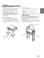
Installing AV Interface Unit
This Unit can be placed inside the trunk, on the
kick panel of the front passenger's seat or
underdash. However, to avoid unnecessary
signal wiring, it is better to mount the Unit as
close as possible to the Display.
DO NOT MOUNT THE INTERFACE UNIT IN
LOCATIONS EXPOSED TO MOISTURE OR
EXTREME HEAT (such as the engine
compartment).
Velcro fastener Mounting:
1. Place a Velcro fastener onto the mounting
surface. The rough side should be facing the unit.
2. Remove the backing to the adhesive on the
Velcro strips. Press the unit onto the mounting
location.
Attaching with screws
1. Place the unit on the location chosen for installation.
2. Mark the screw locations using the unit as a
template.
3. Drill a hole less than 3 mm in diameter.
WARNING
When you are drilling a hole in the car body,
be careful not to damage pipes, tanks or
electrical wiring etc.. It might cause an accident or a fire.
FR
4. Firmly attach the unit using 4 of the supplied selftapping screws (M4 x 14).
Self-tapping screws (M4 x 14)
ES
DE
Velcro fastener
(included)
IT
SE
13-EN
Installation and Connections
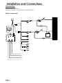
Connections
Make connections correctly.
Improper connections may cause a fire or operation failure.
Basic connection
p
u
1
a
q e
w
s
;
i
r
o
2
q
3
Battery
t
4
y
5
6
8
7
9
d
f
g
h
14-EN
Chassis
1 Foot brake lead (Yellow/Black)
Connect this lead to the foot brake lead powered
when the foot brake is pressed.
g Audio input connectors (AUX 2)
Use these connectors to input the audio signals
from a DVD player, video deck etc.
2 Hand brake lead (Yellow/Blue)
Connect this lead to the hand brake lead
powered when the hand brake is pulled.
h Video input connectors (AUX 2)
Use this connector to input the video signals from
a DVD player, video deck etc.
3 Dimmer lead (White/Blue)
This lead may be connected to the vehicle’s
instrument cluster illumination lead. This will
allow the backlighting of the unit to dim whenever
the vehicle’s lights are turned on.
45Remote control output lead (White/Brown)
To remote control input lead of ALPINE products
used in the system.
6 Reverse Lead (Orange/White)
Use only when a back-up camera is connected.
Connect to the plus side of the car’s reverse
lamp that lights when the transmission is shifted
into reverse (R).
Switches the video picture to the back-up
camera. This is linked with putting the car into
reverse (R).
7 ACC power lead (Red)
To ACC power lead powered when engine key
position is ACC.
8 Fuse (7.5A)
9 Ground lead (Black)
Connect the lead to a good chassis ground on
the vehicle. Make sure the connection is made to
bare metal and is securely fastened using the
sheet metal screw provided.
p
q
w
e
r
t
y
u
i
o
Foot brake lamp
Brake connector (Included)
Foot brake lead
Foot brake switch
Hand (parking) brake lamp
Hand (parking) brake lead
Hand (parking) brake switch
Headphone
Main monitor
Connection cable
If the cable is too short, use the extension cable
(KWE-664N, sold separately).
;
a
s
d
RGB cable
To RGB output terminal
Made by Alpine navigation
Audio input connectors (AUX 1)
Use these connectors to input the audio signals
from a DVD player, video deck etc.
• When connecting a rear view camera, use the “AUX
IN 2”.
To prevent external noise from entering the
audio system.
• Locate the unit and route the leads at least
10cm away from the car harness.
• Keep the battery power leads as far away from
other leads as possible.
• Connect the ground lead securely to a bare
metal spot (remove the coating if necessary)
of the car chassis.
• If you add an optional noise suppressor,
connect it as far away from the unit as
possible. Your Alpine dealer carries various
Alpine noise suppressors, contact them for
further information.
• Your Alpine dealer knows best about noise
prevention measures so consult your dealer for
further information.
FR
ES
DE
IT
SE
f Video input connector (AUX 1)
Use this connector to input the video signals
from a DVD player, video deck etc.
15-EN
R
LIMITED WARRANTY
ALPINE ELECTRONICS OF AMERICA, INC. AND ALPINE OF CANADA INC. ("Alpine"), are dedicated to quality
craftsmanship and are pleased to offer this Warranty. We suggest that you read it thoroughly. Should you have any
questions, please contact your Dealer or contact Alpine at one of the telephone numbers listed below.
This Warranty covers Car Audio Products and Related
Accessories ("the product"). Products purchased in the
Canada are covered only in the Canada. Products
purchased in the U.S.A. are covered only in the U.S.A.
3 You must supply proof of your purchase of the product.
4 You must package the product securely to avoid
damage during shipment. To prevent lost packages it is
recommended to use a carrier that provides a tracking
service.
[LENGTH OF WARRANTY:
[HOW WE LIMIT IMPLIED WARRANTIES:
This Warranty is in effect for one year from the date of the
first consumer purchase.
This Warranty only covers the original purchaser of the
product, who must reside in the United States, Puerto Rico
or Canada.
ANY IMPLIED WARRANTIES INCLUDING FITNESS FOR
USE AND MERCHANTABILITY ARE LIMITED IN
DURATION TO THE PERIOD OF THE EXPRESS
WARRANTY SET FORTH ABOVE AND NO PERSON IS
AUTHORIZED TO ASSUME FOR ALPINE ANY OTHER
LIABILITY IN CONNECTION WITH THE SALE OF THE
PRODUCT.
[WHAT IS COVERED:
[HOW WE EXCLUDE CERTAIN DAMAGES:
This Warranty covers defects in materials or workmanship
(parts and labor) in the product.
ALPINE EXPRESSLY DISCLAIMS LIABILITY FOR
INCIDENTAL AND CONSEQUENTIAL DAMAGES
CAUSED BY THE PRODUCT. THE TERM "INCIDENTAL
DAMAGES" REFERS TO EXPENSES OF
TRANSPORTING THE PRODUCT TO THE ALPINE
SERVICE CENTER, LOSS OF THE ORIGINAL
PURCHASER'S TIME, LOSS OF THE USE OF THE
PRODUCT, BUS FARES, CAR RENTALS OR OTHERS
COSTS RELATING TO THE CARE AND CUSTODY OF
THE PRODUCT. THE TERM "CONSEQUENTIAL
DAMAGES" REFERS TO THE COST OF REPAIRING OR
REPLACING OTHER PROPERTY WHICH IS DAMAGED
WHEN THIS PRODUCT DOES NOT WORK PROPERLY.
THE REMEDIES PROVIDED UNDER THIS WARRANTY
ARE EXCLUSIVE AND IN LIEU OF ALL OTHERS.
[PRODUCTS COVERED:
[WHO IS COVERED:
[WHAT IS NOT COVERED:
This Warranty does not cover the following:
1 Damage occurring during shipment of the product to
Alpine for repair (claims must be presented to the
carrier).
2 Damage caused by accident or abuse, including burned
voice coils caused by over-driving the speaker (amplifier
level is turned up and driven into distortion or clipping).
Speaker mechanical failure (e.g. punctures, tears or
rips). Cracked or damaged LCD panels. Dropped or
damaged hard drives.
3 Damage caused by negligence, misuse, improper
operation or failure to follow instructions contained in the
Owner's manual.
4 Damage caused by act of God, including without
limitation, earthquake, fire, flood, storms or other acts of
nature.
Any cost or expense related to the removal or
reinstallation of the product.
5 Service performed by an unauthorized person, company
or association.
6 Any product which has the serial number defaced,
altered or removed.
7 Any product which has been adjusted, altered or
modified without Alpine's consent.
8 Any product not distributed by Alpine within the United
States, Puerto Rico or Canada.
9 Any product not purchased from an Authorized Alpine
Dealer.
[HOW STATE/PROVINCIAL LAW RELATES TO THE
WARRANTY:
This Warranty gives you specific legal rights, and you may
also have other rights which vary from state to state and
province to province. In addition, some states/provinces do
not allow limitations on how long an implied warranty lasts,
and some do not allow the exclusion or limitation of
incidental or consequential damages. Accordingly,
limitations as to these matters contained herein may not
apply to you.
[IN CANADA ONLY:
This Warranty is not valid unless your Alpine car audio
product has been installed in your vehicle by an Authorized
Installation Center, and this warranty stamped upon
installation by the installation center.
[HOW TO OBTAIN WARRANTY SERVICE:
[HOW TO CONTACT CUSTOMER SERVICE:
1 You are responsible for delivery of the product to an
Authorized Alpine Service Center or Alpine for repair
and for payment of any initial shipping charges. Alpine
will, at its option, repair or replace the product with a
new or reconditioned product without charge. If the
repairs are covered by the warranty, and if the product
was shipped to an Authorized Alpine Service Center or
Alpine, Alpine will pay the return shipping charges.
2 You should provide a detailed description of the
problem(s) for which service is required.
Should the product require service, please call the following
number for your nearest Authorized Alpine Service Center.
CAR AUDIO 1-800-ALPINE-1 (1-800-257-4631)
NAVIGATION1-888-NAV-HELP (1-888-628-4357)
Or visit our website at; http://www.alpine-usa.com
ALPINE ELECTRONICS OF AMERICA, INC., 19145 Gramercy Place, Torrance, California 90501, U.S.A.
ALPINE ELECTRONICS OF CANADA, INC., 777 Supertest Road, Toronto, Ontario M3J 2M9, Canada
Do not send products to these addresses.
Call the toll free telephone number or visit the website to locate a service center.