1
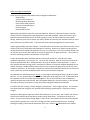
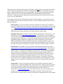
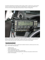
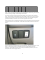
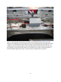
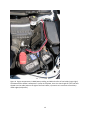
The Elecraft KX3 and One Amateur’s Weekend Project:
A Guide to KX3 Mobile Installation and Operation
Matt Zilmer, W6NIA
23 November, 2012 ‐ Rev B1 (1.6)
Introduction
There can be no doubt that the KX3 is a revolutionary Amateur transceiver. Its technical specs, compact
size, light weight, and general versatility perfectly match the requirements of a portable, mobile, or fixed
station rig. This Guide is written to assist those interested in the KX3’s mobile installation and operation.
Essential factors in mobile operation are significantly different than when operating portable or at a
fixed station. In many ways, operation of any HF transceiver in a mobile setting is non‐optimal. Simply
put, this means that a series of compromises play out for mobile use, including both the installation and
operation of the transceiver.
One aspect of KX3 mobile installation and operation that is emphasized in this Guide is safety. No
mobile installation should detract from it, so safety is treated herein as a serious issue with specific
recommendations that will assist the installer and Amateur operator in maintaining passenger and
driver safety.
Topics in this Guide include the following:
‐ Scope and Warnings
‐ Safety and Legal Considerations
‐ Location and Mounting
‐ Powering the KX3 and KXPA100
‐ Cabling Like a Pro
‐ Speaker Output
‐ Antenna Installation
‐ Operating Tips
‐ Updates To This Guide and In Closing
Scope and Warnings
Scope Note: This Guide’s scope covers only installations in vehicles that have negative ground electrical
systems. If your vehicle has a positive ground system, consult your dealer’s and/or Elecraft’s technical
staff for advice on power considerations for the KX3 and KXPA100.
Warning Note: Some hybrid vehicles don’t use 12 volts for their starting batteries. If your hybrid is in
this category, don’t even think about using its battery to power your KX3 or KXPA100. In many hybrids
an inverter‐based DC to DC converter is used to power the 12V accessories (radio, fans, illumination, etc.)
and any in‐vehicle power sockets. Inverter‐supplied power is usually very noisy, and shouldn’t be used for
the KX3. If in doubt, check your 12V accessory power with an oscilloscope. DC power should meet
Elecraft’s DC power quality specifications. If it doesn’t you may want to add conditioning and filtering
circuits to clean up the DC supply.
1
Safety and Legal Considerations
These are some important KX3 mobile safety and legal considerations:
‐ Road visibility
‐ Access to vehicle controls
‐ Minimizing driver distraction
‐ Intact vehicle safety features
‐ Security of mounted objects
‐ Electrical power
‐ Distracted driver laws
Maximizing road visibility seems like an obvious objective, doesn’t it? But many Amateurs sacrifice
visibility in favor of keeping their radio equipment in view and accessible. Others mount their rigs in
locations that take attention away from what’s going on in front of and around their vehicle while
driving. However you choose to mount your KX3, it should not interrupt your forward visibility or cause
you to take your eyes off the road. This Guide has some mounting suggestions in a later section.
Another goal probably also seems obvious: To be able to drive and control your vehicle normally. Direct
visibility of all mirrors and backup camera displays is essential. Access to all vehicle controls used for
driving should not be impeded or blocked in any way. For example, it’s less critical to block airflow from
an A/C vent rather than make it difficult or clumsy to signal a turn or apply the brakes. Your choice of
the KX3’s mounting location and orientation is crucial here.
A major preventable cause of distracted drivers is personal electronics. Smart phones, tablet
computers, DVD players, TV receivers, etc. ‐ all are on the road now. Most of us have at least some of
these on hand while we drive. Adding the KX3 in this type of situation could complicate it. If you’re
busy with the KX3 when driving, keep in mind that its controls are relatively complex compared to a car
radio or CD player. Standard vehicle electronics aren’t very complex to operate, but not so with some
Amateur transceivers. As an example, compare the controls of a mobile VHF FM transceiver to those of
a KX3. Of the two, the KX3 will demand much more of your attention to operate.
Your Number One Job when driving is Driving. If a passenger is distracting the driver, the driver should
pull over. If a non‐essential device in the vehicle is doing the same thing, turn it off. A distracted driver
has symptoms similar to one with impaired judgment: Lack of use of sensory inputs, and delayed
reactions to those that are perceived. Don’t let Amateur Radio turn you into a statistic, or into another
ham with a sad story to tell others. Let the drive‐while‐texting folks become the statistics.
In aviation, we have a saying: “Aviate, Navigate, Communicate.” First is highest priority. Last is lowest.
You could retask that saying for your priorities when piloting a ground vehicle. Keep your priorities
straight.
Seat belts and airbags are important vehicle safety features; they save lives. Don’t mount your KX3 in a
location that interferes with seat belts or proper airbag “deployment”. The quotes are there for a
reason. If you’ve never had an airbag deploy in front of you, you wouldn’t believe how quickly the KX3
may become a projectile if it’s in the way. Airbags move fast, and with explosive force. Anything
blocking an airbag’s path should be moved out of the way. If there’s any doubt about your vehicle’s
2
airbag deployment paths, consult your dealer’s technical staff. Airbag locations are marked with a
prominent embossed label.
I mentioned “a projectile”, above. In a vehicle moving at 65 MPH [105 KPH], a two pound KX3 on a
ballistic trajectory can be deadly. Simply put, your KX3 should be securely mounted to a stationary
surface in the vehicle interior. Seems like common sense, right? Common sense isn’t all that common,
unfortunately. There’s more about mounting techniques in a subsequent section of this Guide.
One final safety factor: Electrical Power. Don’t compromise on the quality, security, location, and
especially protection of your DC supply cabling to the KX3. If you have an electrical fire while in motion
because of a poor or temporary installation, it’s too late to complain, “But it’s only temporary!” Man,
oh man ‐ talk about distractions while driving!
Distracted Driving Laws: Amateur Radio has come under some of the same fire that is hitting mobile cell
phone users. It is true that many of the same hazards exist for both practices, but hams are more used
to mobile operations than the general population. For some excellent legal and practical considerations,
see the November, 2012 QST magazine, p 81 and 82. Such laws are a mixed bag. The states of
California, Illinois, Washington, and Hawaii specifically exempt the Amateur population from the most
onerous provisions of their distracted driver laws, however many of the state laws as‐written are
ambiguous, and refer to “communications with electronic devices”. Be aware of the law in your state!
Most of these require the use of “hands‐free” devices.
Wireless hands‐free accessories for mobile two‐way are available, but the market is slim. This may be
due to low consumer demand. The few Bluetooth hands‐free add‐ons for two‐way are marketed for law
enforcement, and are pricey.
Vehicle, passenger, and driver safety is a big topic with a wide range of considerations. Make yourself
aware of the factors in your own mobile installation that could become problems while you’re at the
wheel. Install and operate your KX3 accordingly. If you’re planning a new car/SUV/truck/RV purchase
and also would like a KX3 mobile installation in it, survey the interior, electrical system, cable runs and
raceways, and vehicle construction before signing on the dotted line. You may want to discuss
mounting and cabling arrangements with the dealer’s technical staff beforehand.
Location and Mounting
Ideally, mobile‐mounting your KX3 provides the following benefits:
‐ Accessible and directly visible controls and display with one‐handed operation;
‐ A minimum of cable clutter;
‐ Least possible amount of divided attention while driving – most important!
The good news is that if the KX3 is near enough in front of you, using the controls one‐handed shouldn’t
pose a big challenge, even while driving. Hints are:
‐ Make sure the KX3 is mounted to one side of the steering wheel. This avoids a cross‐handing
problem. It is best if the KX3 front panel controls are within an easy reach, or maybe right at
your fingertips;
‐ It’s a great idea if you get 100% used to the KX3’s controls before ever using the rig while you’re
driving. It’s a case of, “DO try this at home.”
3
With the KX3, we’re fortunate to have the I/O connectors on the left panel. For left hand‐drive vehicles
at least, most of the cabling can be routed over the edge of the dashboard, or behind the instrument
panel. The BNC and SMA connectors can be right‐angled to the rear of the KX3, keeping the antenna
cables out of the way. Don’t leave cables scattered on your dashboard because they can be a
distraction. Having cables drop off and get wound around your hands or feet makes this much worse.
There is more on cabling below.
Several types of vehicle mount that work with the KX3 are readily available. You can always roll your
own if needed, but the easiest and usually best course is to use a manufactured mount from one of the
following categories:
‐
Hard mounting. This is the case where you’d have to develop your own mount or adapt one
that exists. A good source for hard mounts is National Products, with RAM Mount as their brand
name: (http://www.rammount.com/Products/VehicleMounts/tabid/4077/Default.aspx#/). The
downside to a hard mount is that you’ll need to drill holes for the mount base. The upside:
Hard mounting is the most physically secure type, with a lot of safety margin.
‐
Dashboard seam mount. This type of mount is meant for crowded small vehicle interiors. One
manufacturer is ProClip (http://www.proclipusa.com/). The mount base is inserted between
seams in panel or dashboard, or around dashboard seams (spanning two seams, or between the
two edges of a panel component). I’ve seen these support loads up to five pounds, including
ruggedized laptops for field service, though two mounts are needed for this type of load.
Almost all the different ProClip mount bases come out to an AMPS hole pattern. Figure 1, on
the next page, shows this type of mount with RAM cradle. described below. A KX3 is shown in
the cradle. At least in this installation, the mount is very secure and KX3 “wobble” is minimal.
‐
Vacuum mount. An example is a family of products manufactured by Seasucker of Florida
(http://www.seasucker.com/shop/seasuckerram‐x‐mount‐phonegps‐holder/). They’re for use
in marine environments to secure heavy loads to bulkheads and acrylic surfaces. An example is
shown in Figure 2. Seasuckers are available in 4‐1/2‐and 6‐inch vacuum diaphragm diameters.
The 4‐1/2‐inch unit is adequate when used with the KX3 on auto glass, and is rated at 120
pounds for either axial or radial load. Vacuum mounts do not generally work well on curved
surfaces, but a side window or windshield should be okay. This type of mount requires an
occasional push of the plunger to maintain its seal on auto glass. “Occasional” means about
once a week. There is an indicator showing the vacuum level and if it’s getting too low. In the
author’s opinion, the Seasucker is probably one of the two best no‐holes mobile mount bases
available.
‐
Suction mount. There are a lot of these available, for use with device types from iPods to
navigation units. You would probably want a suction mount with a 3‐inch or larger suction cup
to secure the KX3 against windshield or side‐window glass, or on the dashboard. Most come
with an adhesive disc that allows a solid mount point on any surface. Arkon is one
manufacturer: http://www.arkon.com/. There are many others. Any suction mount you use
should be rated at five times the KX3’s featherweight of 2 pounds. Suction mounts don’t
perform as well as vacuum mounts, and may lose their grip – dropping the KX3 in your lap when
4
it’s least convenient. Suction mounts should be reseated several times a month to maintain
retention. They only last about a year, so keep that in mind.
‐
Air vent mount. Most of these are designed for use with very lightweight devices like smart
phones and media players. They’re available at electronics retailers such as Best Buy. One
manufacturer is Bracketton. Vent mounts may sag and most will need periodic adjustment.
This alternative is not recommended, but may be the only choice for some mobile users with
limited space. Don’t count on air vent mounts lasting very long: They have too many moving
parts, most of them are too fragile for a lot of mount / dismount cycles, and they’re not rated
for the KX3’s weight.
Figure 1. ProClip dashboard mount in a 2012 Honda Civic supporting a RAM double‐arm clamp from
an AMPS 1” ball adapter. The cradle retaining the KX3 is the same unit as shown in Figure 2 (also
made by National Products – tradename: RAM).
5
The Seasucker 6018 with a mounted KX3 is shown in Figure 2, below. Using the 4‐1/2” vacuum mount,
the KX3 is secured to the driver side window of a 2012 Honda Civic. Also note the cable dress and
clearance to the curtain airbag’s deployment path (driver’s side post in background).
Figure 2. Seasucker 6018 vacuum mount with a KX3 in a Honda Civic. Note the use of the Elecraft KX3‐
PCKT cable set on the left. The right angle arrangement keeps cable layout tidy and out of the way.
Below the audio cables (left side), a retaining clip is used to keep the bundle together.
Powering the KX3 and KXPA100
Vehicle accessory power systems are notorious for conductive emissions, and they may come in many
forms – both transient and steady state:
‐
‐
‐
‐
‐
Load dump surges
Engine starting transients
Inverter noise (hybrids, especially)
Poor line isolation (fan motors, relays, and solenoids)
Transients due to accessories being switched on and off (a/c compressors and electric fuel
pumps are two examples)
6
The very best source of power in a typical vehicle is a secondary battery. Note that I didn’t write this as
“the engine start battery”. Your engine start battery will work too if it’s 12V, or you could tap into an
unused branch circuit at the fuse block. Least desirable as a power source is the vehicle’s accessory
electrical system.
A secondary battery that’s well‐isolated from the vehicle’s engine‐start system will work best for the
KX3. There are a number of isolators made for 12VDC systems, and these are used to connect the
secondary battery to the vehicle’s DC system only for charging, as needed. Some isolators also supply
transient suppression and filtering, and over‐current protection. In general, this will eliminate or
suppress conducted emissions from the primary accessory power system. See
http://www.powerstream.com/battery‐isolator‐solid‐state.htm for an example of an isolator.
In practice, not everyone can fit in a second storage battery to use for the KX3. Small cars in particular
have little space for extras like this. You might be able to fit a small battery under a seat or in the trunk,
but take care to protect its terminals from being shorted, and it should be securely mounted. Most of us
would probably choose to use the vehicle’s engine start battery as the primary KX3 power source. This
approach is generally the best compromise for power quality, cost, and convenience. The KX3 power
distribution and conversion example in this Guide uses the engine start battery as the source.
The KX3 was designed to operate from clean DC power – batteries – and is not immune to automotive
DC power supply impurities (I call this “gudge”). If any DC line noise is present at audio frequencies, it
will be readily audible in the KX3’s speaker and PHONES output. (The microphone amplifier circuits are
not as susceptible to line noise.) One way to mitigate a DC source with audio frequency noise is to use
the KX3’s RX SHFT function to move amplification away from the audio frequencies, up to 8 KHz. This
works amazingly well. But it’s even better if you remove the DC line noise entirely, or lessen it
substantially.
Power distribution to the KX3 and the KXPA100 may be routed via an automotive relay with instrument
panel control via a switch. Shown in the wiring diagram, Figure 3, this separate switching allows the
operator to avoid damaging engine start transients at the KX3. The switch and relay can be purchased
from your local auto parts dealer. See Figure 5 for a photo of the interior penal switch in a Honda Civic.
Figure 5 shows the relay enclosure, mounted in the Civic’s trunk.
Caution: DO NOT use panel switches like the one shown to directly switch loads such as the KX3 or
KXPA100. Switches of this type are designed for the amount of current a relay coil needs to energize,
0.5A or less. Let the relay do the heavy lifting; it only costs a couple of dollars.
Figure 3, below, shows a wiring diagram for a KX3 and a KXPA100 installation – both powered from the
vehicle’s engine start battery. This design uses a relay to isolate the KX3 / KXPA100 branch circuit.
Figure 4 is a schematic diagram of the relay and power interconnect circuits. The diode is used to
protect the contacts on the panel switch shown in Figure 4 from back EMF when the relay coil is de‐
energized.
7
Figure 3. Wiring Diagram: Example of KX3 and KXPA100 power and antenna cabling.
Figure 4. Relay and interconnection schematic.
In Figure 2, take a close look at the KX3’s DC power input. The DC to DC converter shown eliminates
whatever power impurities remain at this end of the interior DC branch circuit. Being a boost‐buck
regulator, the converter can accept a wide range of input voltages and produces a steady 13.8VDC
(adjustable). The converter used in this example installation is made by QSKJ (model QS‐1212CCBA‐
80W). In addition to cleaning up the DC, the converter reduces voltage sag from the smaller gauge
interior wiring. In order to prevent the converter from introducing its own emissions, a Laird LFB174095
ferrite core was used with 3 turns of the KX3’s stock cable. This killed all converter emissions.
See http://ca.picclick.com/DC‐DC‐Converter‐QS‐1212CCBA‐80W‐Power‐Supply‐251036051706.html.
Cabling Like A Pro
If you take time to plan your cabling carefully, power and antenna cables will be visible only at the KX3,
under the hood [bonnet] when it’s up, or in the trunk [boot]. The idea is to keep your car or truck
interior looking uncluttered. If you don’t care about cable placement you may ignore this section. Some
people are neat freaks, others aren’t.
There are numerous useful tricks in performing a pro installation. We can learn a lot from mobile audio
installers on this, taking advantage of the fact that there is a general trend to install monster audio gear.
Many vehicle audio systems involve placing a high‐power amplifier in the trunk, with a head‐end unit in
the cab, and heavy power and speaker cabling in between. That same placement concept can be used
for the KX3 and KXPA100.
8
Note: Although the KXPA100 is not yet available from Elecraft, as of July, 2012, the design team
confirmed it will use the 30A Anderson Power Pole connector, so design accordingly.
When exiting your power cable from the engine compartment, first locate a suitable punch‐out
grommet or seal. Most of these are circular, and vehicle manufacturers leave a few spares for
aftermarket equipment installations. Locations and sizes of these entry grommets vary by vehicle. Your
dealer’s technical staff may be able to assist you in finding an appropriate power entry point. Be sure
and replace the grommet when done (yes, with a hole cut for the cable).
Using existing interior cable raceways is recommended. To access these, you’ll usually need to remove
interior panels. Most raceways are located under the doors, and there is normally enough space left to
lay in your power, antenna, and any control cabling. Use caution when removing panels and don’t lose
any of the retainer hardware. You’ll need it when replacing the panels.
When it comes to your vehicle’s trunk, consider laying in and securing all cables under the liner. Not all
trunks have these, but most do. Since the trunk’s main purpose is for stowage, you probably want to
protect the cables from getting beat up by whatever you toss in there. Use cable ties liberally, especially
when suspending wiring and cables from an understructure or near vertical mounting locations.
Here are a few hints that apply whether you install your KX3 cabling or have someone do it for you:
‐ Use the correct wire gauge (see Table 1 below) and terminations;
‐ Make room for fuse holders at the source end of each power cable run;
o Blade‐style fuses and fuse holders are readily available at auto parts stores and mobile
audio dealers;
o Fuses located under the hood should be housed in waterproof fuse holders;
o All fuses, of any type, should be DC‐rated.
‐ Try to route engine compartment cabling so it can be cable‐tied to the wiring harness [loom];
‐ Where possible, use existing cable raceways;
‐ Avoid radical bends in cables and “crimp points” where the cable jacket can get mashed,
mangled, squeezed, ruptured or exposed to similar indignities;
‐ Allow adequate service loops at cable ends;
Auto Electronics 101: Every circuit that branches from a source should be protected for over‐current.
At a minimum, you should protect your radio branch circuit with a fuse at the battery. Figures 6, 7, and
8 illustrate over‐current protection at multiple locations:
‐
‐
‐
Battery: 40A inline cartridge fuse in waterproof holder (Motorola p/n 9C84277B02);
Two branches from relay: 30A blade fuses in water resistant holders;
West Mountain APP Power Strip: five branches, each protected by a blade fuse.
Wire gauge is an important factor because it determines the loaded terminal voltage at the KX3 and/or
KXPA100. Some typical power cable runs are shown in Table 1, below. The goal is to maintain 13.0VDC
or higher at the load when the engine is running. Voltages may vary lower than shown when the engine
is idle or off, so bigger is better. Use high quality copper‐core power cabling, not monster speaker zip
cord.
9
AWG
14
12
10
8
Ω / kft (km)
2.58 (8.51)
1.62 (5.34)
1.02 (3.37)
0.64 (2.11)
L in ft (m)
6 (2)
10 (3.3)
15 (4.9)
25 (8.3)
Current
2A
2A
25A
25A
Load Volts
13.7
13.7
13.0
13.0
Use Case or Example
KX3‐only in small car
KX3‐only in pickup truck
KX3 in cab with KXPA100 under seat
KX3 in cab with KXPA100 in trunk
Table 1. Practical wire gauges and lengths for the KX3 and KXPA100 in a mobile setting. DC resistances
shown are at 77 deg F, 25 deg C. Source voltage used is 13.8VDC.
For normally constructed, negative ground vehicles (Unibody), only the positive lead is needed for
power. The vehicle body can and should be used, where possible, as the return or ground. Running a
separate return is generally not necessary and saves money as well. Seat‐mount bolts make good
ground bonds and they’re accessible. You can use them as grounds near the loads.
When you perform your own voltage drop calculations, be sure and include the contact resistance of all
connectors in the series circuit to the load. The table above assumes APP connectors as shown in the
photos.
Figure 5. 40A branch circuit switch on the Civic’s instrument panel. There were two “dummies” in this
panel, so I removed the rightmost one and filled its slot with a Honda standard panel switch
replacement. The KX3 and mount aren’t seen, but they are located directly above this panel. The
microphone cable is shown hanging at the left.
10
Figure 6. Trunk‐mounted relay enclosure and cabling. The 8 AWG battery power feed enters the
enclosure via the APP pair on the left. Behind it is the control input wiring from the panel switch shown
in Figure 5. The 10 AWG power cable exiting to the right is protected by a 30A inline blade fuse. It’s
routed under the rear seat and carpet to the in‐cab West Mountain 5x APP strip shown in Figure 6 on
the next page. The enclosure and all cable ties are secured to the rear deck’s metal understructure.
Note the hard‐point ground at the right – used to provide a solid ground for the antenna.
11
Figure 7. West Mountain APP strip feeding the KX3 and other radios. The KX3’s DC power is fed through
the DC‐DC converter shown above the APP strip. The 10 AWG power feed from the trunk‐mounted
relay enclosure is visible on the left. The 10 AWG is fished from the front edge of the rear seat under
the carpet to its exit point about six inches to the left of the APP strip (under the passenger seat). An
upholstery “hook knife” was used to slit the carpet and liner to allow the cable an exit. The ground used
at this location is one of the passenger seat bolts. The input is fused at 10A, which will be changed to
30A when the two empty circuits are populated (future planning).
12
Figure 8. Engine compartment, 8 AWG battery cabling, and 40A inline fuse in fuse holder (upper right).
The Motorola fuse holder is waterproof. Unseen in this photo, there is a short length of 5/16” fuel hose
slipped over the cable jacket to the right of the fuse holder, to protect it as it traverses several sharp
metal edges (weld points).
13
Speaker Output
The KX3’s PHONES socket is a stereo 3.5mm type. If your vehicle has a 3.5mm AUX input, you can buy a
patch cable to bring the KX3’s PHONES audio to your car’s audio system. Elecraft sells a nice right‐angle
3.5mm cable for this purpose, and they also have a kit of four cables available for a complete PC‐sound
and control connection (SKUs E980230 and KX3‐PCKT, respectively). The Elecraft cables work very well
for KX3 mobile sound connections because of the right‐angle connector at the KX3. They’re high quality
cables, not generally what you would find at Radio Shack, Best Buy, or Target.
It’s best to isolate the KX3 output with a 1:1 600ohm or lower transformer. This will help prevent audio
artifacts from being heard at high volume, and avoids ground loops (Pin 1 problems).
If your vehicle doesn’t have an AUX audio input, there are kits available for retrofitting older car audio.
Most of these use the CD Changer input. If you want separate powered speakers, there are dozens of
choices but make sure you can fit them in the interior, and that they’re securely mounted.
Antenna Installation
Figures 9 and 10, on the next page, show one possibility for a mobile HF antenna. I’m using this on my
Honda Civic regularly. The antenna shown in Figure 9 shows a Hustler single‐bander for 40m, using the
short 22” mast and a base spring at the resonator mount point. This is an inexpensive type of mobile
antenna, and not incredibly efficient, but it does work. I’ve had 60 or 70 SSB contacts while mobile, and
about 200 CW contacts while stationary using the Hustler as shown.
The tripod mount configuration shown in Figures 9 and 10 is extremely robust. The main mount and
feed point is at the rear lip of the trunk lid. Two Comet RS480 5/8” trunk mounts are used at the
forward lip for longitudinal and lateral stability. I’ve been able to use the largest Hustler resonators, and
even a home‐brew 100W resonator that I hand‐built for a 5 MHz MARS frequency. The two forward legs
of the tripod are made of 3/8” fiberglass rod acquired from Granger. The mast brackets are made from
scrap aluminum found around my shop. Level adjustment is via the two 3/8‐24 coupling nuts near the
front attach points. Metal and fiberglass are held together at both ends of each forward leg, using two‐
part epoxy. Heat shrink tubing is used to hide the ugly part of each metal‐fiberglass junction.
Hints:
‐ If you’re stationary, lay out a couple of quarter wave radials and attach them to the vehicle
chassis. Fan them out to the sides from the rear of the vehicle. This really helps with efficiency
and gets a bigger signal on the air. QRP mobile isn’t really a good combination with small
antennas and no substantial counterpoise. The vehicle chassis doesn’t really help much as a
counterpoise, unless the vehicle is RV‐sized. Putting out radials will always improve your
radiated signal.
‐ Use higher power levels. The KXPA100/KXAT100 will help with this.
‐ The part of the antenna mount that is mechanically attached to the vehicle should be electrically
grounded to a hard point on the vehicle’s body. Don’t depend on a trunk lid, and its attachment
via hinges to the rear deck, to be a reliable ground. Use some coax braid from the mount base
and route it along the trunk frame using cable ties as needed. There’s usually a good attach
point right on the body metal near the inner part of the trunk hinge. If you examine Figure 6
closely, there is a good hard attach point shown at the far right.
14
There are probably dozens of more electrically efficient mobile antennas to choose from. My favorite is
the HiQ, but it’s not a very comfortable fit for a small car like a Civic.
Figure 10. Detail shot of the tripod mount and
the Hustler short mast.
Figure 9. Trunk lip‐mounted Hustler short mast
with a 40m resonator attached.
15
Operating Tips
Though the KX3 is an excellent mobile platform, there are a few hints that may assist operators. Some
of these are described below. As emphasized elsewhere in this Guide, safety is a primary consideration.
While you’re stationary, put in the settings you’ll use while driving. Adjust the AF and RF GAIN
levels, and set the BAND and VFO A / B up near the frequency you intend to use. Turn the
PREAMP on or off as needed, and set the Noise Blanker on to kill ignition and other radiated
noise. Make sure all the KX3 cabling is in place, and that the rig is secured in its mount. Set the
MODE as desired.
‐
While driving, use the UP / DN buttons on the MH3 mic for frequency changes, rather than
twisting the VFO A knob. Avoid “frobbing” the VFO except as needed for fine tuning. The
mental feedback loop between turning the VFO knob and watching the display is potentially a
100% distraction from driving. However, you will need to make fine adjustments once in a
while. Instead of watching the display, listen to the signal instead, as you adjust the VFO.
‐
Unless you’re a seasoned CW op, stick to voice modes while driving. CW using the KXPD3
(attached to the KX3) is not recommended while mobile. If CW is your mode, you’ll likely want
to remote‐mount a key or paddle in a comfortable position, but probably away from the KX3.
‐
Use the SCAN function instead of “roving” via VFO A. This requires that a memory with A and B
frequencies be recalled before scanning. You may want to set up specific memories for mobile
operation just for this purpose. You can use the MH3 microphone’s UP and DN switches to halt
a scan in progress. The KX3 will scan manually if you use the mic switches ‐ either tap or hold.
‐
If you’re driving in the city, the KX3 could experience various signal degradations and
obstructions. Sources are buildings and other large objects like bridges, fence lines, high‐voltage
transmission lines, etc. These are unavoidable, and are part of the mobile operator’s
“landscape”.
‐
If you’re operating mobile in the countryside, you may notice several types of RFI. Sources
include: power lines and utility equipment, street lighting, diesel fuel injectors, ignition noise,
etc. The KX3’s Noise Blanker is very effective in eliminating these.
‐
Set up PF1 and PF2 for frequently‐used MENU functions. For example, PF1 can be set up to
toggle the backlight on/off, and PF2 set up for DUAL RX on/off. Don’t put yourself in a position,
while driving, of needing to access MENU functions at all.
16
Standard Disclaimer, Updates To This Guide, and In Closing
As stated in the subtitle, this guide is “one ham’s weekend project”. It’s not meant to be all‐definitive,
because the ham population chooses from a diverse set of vehicles and there is a lot of variation in
mobile conditions for operators – for a variety of reasons. Again, safety should not be compromised in
any case, and frankly, each operator must make his or her own choices for mounting, cabling, over‐
current protection, etc. I suppose that this is a soft way of saying that the neither Elecraft nor the
author are responsible for the decisions you make when it comes to any Amateur mobile installation,
even if you follow this guide’s installation to the last detail.
Periodic changes and corrections to this document may be necessary and will be published when
needed. Readers are encouraged to contact the author with any type of feedback. Email:
[email protected]. I hope this guide to was useful to you. That is my goal.
Revision History and Credits
Revision
Date
Change Set
0.9
0.95
1.0
21 JUL 2012
23 JUL 2012
28 JUL 2012
1.1
1.2
30 JUL 2012
2 AUG 2012
1.3
10 OCT 2012
1.4
18 OCT 2012
1.5
28 OCT 2012
B1 (1.6)
23 NOV 2012
First rough draft, review by Elecraft. Content only.
Added some photos, electrical schematic.
First review copy, format cleanups. Worked with Metro Honda
service dept. for airbag deployment and Seasucker safety checks.
Added battery side and pull‐through pics (cabling).
Restructured with better formatting for photos;
added explanation of the schematic, coupled with the
under‐hood and trunk photos.
Re‐wrote antenna mount section, showing the tripod after
Initial testing. Thanks to Roger Wright of Advanced Radio
Workshop for the assistance! Thanks to Don Wilhelm for proofreading.
Cleaned up formatting for fewer total printed pages. Better yet, don’t
print this Guide unless you need to! If you really need to print it, and
are able ‐ print on both sides, please.
Figures 1, 6, 8, and 9 revised to latest changes. Some figure caption
changes to match these. Figures 10 and 11 added, with captions
(ProClip dash mount options). Minor grammatical text edits. Thanks to
ProClip for the images used in Figures 10 and 11.
Updated photos (Figure 1 inserted, and 7, 10, 11 updated). Added text
for ProClip dashboard seam mount. Changed revision markings to
Elecraft‐standard. Added precaution as to power cable quality (thanks
to [email protected] for this reminder).
17