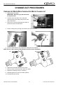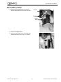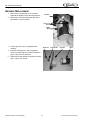
1
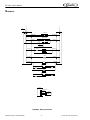
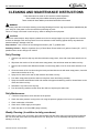
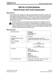
IDC 2XX WITH COLD CARBONATION Service Manual Release Date: October 2, 2007 Publication Number: 621057403SER Revision Date: August 3, 2010 Revision: A Visit the IMI Cornelius web site at www.cornelius.com for all your Literature needs. The products, technical information, and instructions contained in this manual are subject to change without notice. These instructions are not intended to cover all details or variations of the equipment, nor to provide for every possible contingency in the installation, operation or maintenance of this equipment. This manual assumes that the person(s) working on the equipment have been trained and are skilled in working with electrical, plumbing, pneumatic, and mechanical equipment. It is assumed that appropriate safety precautions are taken and that all local safety and construction requirements are being met, in addition to the information contained in this manual. This Product is warranted only as provided in Cornelius’ Commercial Warrant applicable to this Product and is subject to all of the restrictions and limitations contained in the Commercial Warranty. Cornelius will not be responsible for any repair, replacement or other service required by or loss or damage resulting from any of the following occurrences, including but not limited to, (1) other than normal and proper use and normal service conditions with respect to the Product, (2) improper voltage, (3) inadequate wiring, (4) abuse, (5) accident, (6) alteration, (7) misuse, (8) neglect, (9) unauthorized repair or the failure to utilize suitably qualified and trained persons to perform service and/or repair of the Product, (10) improper cleaning, (11) failure to follow installation, operating, cleaning or maintenance instructions, (12) use of “non-authorized” parts (i.e., parts that are not 100% compatible with the Product) which use voids the entire warranty, (13) Product parts in contact with water or the product dispensed which are adversely impacted by changes in liquid scale or chemical composition. Contact Information: To inquire about current revisions of this and other documentation or for assistance with any Cornelius product contact: www.cornelius.com 800-238-3600 Trademarks and Copyrights: This document contains proprietary information and it may not be reproduced in any way without permission from Cornelius. Printed in U.S.A. TABLE OF CONTENTS Safety Instructions . . . . . . . . . . . . . . . . . . . . . . . . . . . . . . . . . . . . . . . . . . . . . . . . . . . . . . . . . . . . 1 Read and Follow all Safety Instructions . . . . . . . . . . . . . . . . . . . . . . . . . . . . . . . . . . . . . . . . . 1 Recognize Safety Alerts. . . . . . . . . . . . . . . . . . . . . . . . . . . . . . . . . . . . . . . . . . . . . . . . . . 1 Different Types of Alerts. . . . . . . . . . . . . . . . . . . . . . . . . . . . . . . . . . . . . . . . . . . . . . . . . . 1 Safety Tips . . . . . . . . . . . . . . . . . . . . . . . . . . . . . . . . . . . . . . . . . . . . . . . . . . . . . . . . . . . . 1 Qualified Service Personnel. . . . . . . . . . . . . . . . . . . . . . . . . . . . . . . . . . . . . . . . . . . . . . . 1 Safety Precautions . . . . . . . . . . . . . . . . . . . . . . . . . . . . . . . . . . . . . . . . . . . . . . . . . . . . . . 2 Shipping And Storage . . . . . . . . . . . . . . . . . . . . . . . . . . . . . . . . . . . . . . . . . . . . . . . . . . . 2 CO2 (Carbon Dioxide) Warning . . . . . . . . . . . . . . . . . . . . . . . . . . . . . . . . . . . . . . . . . . . . 2 Mounting in or on a Counter. . . . . . . . . . . . . . . . . . . . . . . . . . . . . . . . . . . . . . . . . . . . . . . 2 Introduction . . . . . . . . . . . . . . . . . . . . . . . . . . . . . . . . . . . . . . . . . . . . . . . . . . . . . . . . . . . . . . . . . 3 Description . . . . . . . . . . . . . . . . . . . . . . . . . . . . . . . . . . . . . . . . . . . . . . . . . . . . . . . . . . . . . . . . 3 Theory of Operation . . . . . . . . . . . . . . . . . . . . . . . . . . . . . . . . . . . . . . . . . . . . . . . . . . . . . . . . . 3 Specification . . . . . . . . . . . . . . . . . . . . . . . . . . . . . . . . . . . . . . . . . . . . . . . . . . . . . . . . . . . . . . 3 Flow Diagrams - Eight Flavor Unit . . . . . . . . . . . . . . . . . . . . . . . . . . . . . . . . . . . . . . . . . . . . . . . 4 Flow Diagrams - Ten Flavor Unit . . . . . . . . . . . . . . . . . . . . . . . . . . . . . . . . . . . . . . . . . . . . . . . . 5 E – Board Off Cycle Agitation Adjustments . . . . . . . . . . . . . . . . . . . . . . . . . . . . . . . . . . . . . . . 6 Wiring Diagram . . . . . . . . . . . . . . . . . . . . . . . . . . . . . . . . . . . . . . . . . . . . . . . . . . . . . . . . . . . . 7 Schematic . . . . . . . . . . . . . . . . . . . . . . . . . . . . . . . . . . . . . . . . . . . . . . . . . . . . . . . . . . . . . . . . 8 Cleaning and Maintenance Instructions . . . . . . . . . . . . . . . . . . . . . . . . . . . . . . . . . . . . . . . . . . . 9 Daily Cleaning . . . . . . . . . . . . . . . . . . . . . . . . . . . . . . . . . . . . . . . . . . . . . . . . . . . . . . . . . . . . . 9 Daily Maintenance . . . . . . . . . . . . . . . . . . . . . . . . . . . . . . . . . . . . . . . . . . . . . . . . . . . . . . . . . 9 Weekly Cleaning. . . . . . . . . . . . . . . . . . . . . . . . . . . . . . . . . . . . . . . . . . . . . . . . . . . . . . . . . . . 9 Monthly Cleaning . . . . . . . . . . . . . . . . . . . . . . . . . . . . . . . . . . . . . . . . . . . . . . . . . . . . . . . . . . 10 Yearly Maintenance . . . . . . . . . . . . . . . . . . . . . . . . . . . . . . . . . . . . . . . . . . . . . . . . . . . . . . . . 10 Cold Plate (Yearly Maintenance)) . . . . . . . . . . . . . . . . . . . . . . . . . . . . . . . . . . . . . . . . . . . . . 10 Dispensing Valve (Daily Cleaning) . . . . . . . . . . . . . . . . . . . . . . . . . . . . . . . . . . . . . . . . . . . . 10 Product Tubing ( Monthly Cleaning) . . . . . . . . . . . . . . . . . . . . . . . . . . . . . . . . . . . . . . . . . . . 10 Sanitize Pre-Mix and Post Mix tank System . . . . . . . . . . . . . . . . . . . . . . . . . . . . . . . . . . 10 Sanitize Syrup Lines . . . . . . . . . . . . . . . . . . . . . . . . . . . . . . . . . . . . . . . . . . . . . . . . . . . . 11 Replenishing CO2 Supply ( As Required). . . . . . . . . . . . . . . . . . . . . . . . . . . . . . . . . . . . . . . . 11 Maintenance . . . . . . . . . . . . . . . . . . . . . . . . . . . . . . . . . . . . . . . . . . . . . . . . . . . . . . . . . . . . . . . . 12 Daily (or as required) . . . . . . . . . . . . . . . . . . . . . . . . . . . . . . . . . . . . . . . . . . . . . . . . . . . . . . . 12 Checking CO2 Supply . . . . . . . . . . . . . . . . . . . . . . . . . . . . . . . . . . . . . . . . . . . . . . . . . . 12 Checking for CO2 and water leak . . . . . . . . . . . . . . . . . . . . . . . . . . . . . . . . . . . . . . . . . 12 Monthly . . . . . . . . . . . . . . . . . . . . . . . . . . . . . . . . . . . . . . . . . . . . . . . . . . . . . . . . . . . . . . . . . 12 Yearly . . . . . . . . . . . . . . . . . . . . . . . . . . . . . . . . . . . . . . . . . . . . . . . . . . . . . . . . . . . . . . . . . . 12 Water Pump Maintenance (or after water system disruption) . . . . . . . . . . . . . . . . . . . . 12 Cleaning CO2 Gas Check Valve . . . . . . . . . . . . . . . . . . . . . . . . . . . . . . . . . . . . . . . . . . 12 Change-out Procedures . . . . . . . . . . . . . . . . . . . . . . . . . . . . . . . . . . . . . . . . . . . . . . . . . . . . . . 13 Carbonated Water/Non Carbonated Water Change-out . . . . . . . . . . . . . . . . . . . . . . . . . . . . 13 Motor Replacement . . . . . . . . . . . . . . . . . . . . . . . . . . . . . . . . . . . . . . . . . . . . . . . . . . . . . . . . 14 Gearbox Replacement . . . . . . . . . . . . . . . . . . . . . . . . . . . . . . . . . . . . . . . . . . . . . . . . . . . . . . 15 Troubleshooting . . . . . . . . . . . . . . . . . . . . . . . . . . . . . . . . . . . . . . . . . . . . . . . . . . . . . . . . . . . . . 16 Diagnostics Guide for the Main Control Board . . . . . . . . . . . . . . . . . . . . . . . . . . . . . . . . . . . 19 Troubleshooting . . . . . . . . . . . . . . . . . . . . . . . . . . . . . . . . . . . . . . . . . . . . . . . . . . . . . . . . . . . 20 Beverage Not Dispensing . . . . . . . . . . . . . . . . . . . . . . . . . . . . . . . . . . . . . . . . . . . . . . . 20 Flat Drinks . . . . . . . . . . . . . . . . . . . . . . . . . . . . . . . . . . . . . . . . . . . . . . . . . . . . . . . . . . . 21 No Carbonated Water . . . . . . . . . . . . . . . . . . . . . . . . . . . . . . . . . . . . . . . . . . . . . . . . . . 22 IDC 2XX Training Manual SAFETY INSTRUCTIONS READ AND FOLLOW ALL SAFETY INSTRUCTIONS Safety Overview • Read and follow ALL SAFETY INSTRUCTIONS in this manual and any warning/caution labels on the unit (decals, labels or laminated cards). • Read and understand ALL applicable OSHA (Occupational Safety and Health Administration) safety regulations before operating this unit. Recognition Recognize Safety Alerts ! This is the safety alert symbol. When you see it in this manual or on the unit, be alert to the potential of personal injury or damage to the unit. DIFFERENT TYPES OF ALERTS ! DANGER: Indicates an immediate hazardous situation which if not avoided WILL result in serious injury, death or equipment damage. ! WARNING: Indicates a potentially hazardous situation which, if not avoided, COULD result in serious injury, death, or equipment damage. ! CAUTION: Indicates a potentially hazardous situation which, if not avoided, MAY result in minor or moderate injury or equipment damage. SAFETY TIPS • Carefully read and follow all safety messages in this manual and safety signs on the unit. • Keep safety signs in good condition and replace missing or damaged items. • Learn how to operate the unit and how to use the controls properly. • Do not let anyone operate the unit without proper training. This appliance is not intended for use by very young children or infirm persons without supervision. Young children should be supervised to ensure that they do not play with the appliance. • Keep your unit in proper working condition and do not allow unauthorized modifications to the unit. QUALIFIED SERVICE PERSONNEL ! WARNING: Only trained and certified electrical, plumbing and refrigeration technicians should service this unit. ALL WIRING AND PLUMBING MUST CONFORM TO NATIONAL AND LOCAL CODES. FAILURE TO COMPLY COULD RESULT IN SERIOUS INJURY, DEATH OR EQUIPMENT DAMAGE. Publication Number: 621057403SER -1- © 2007-2010, IMI Cornelius Inc. IDC 2XX Training Manual SAFETY PRECAUTIONS This unit has been specifically designed to provide protection against personal injury. To ensure continued protection observe the following: ! WARNING: Disconnect power to the unit before servicing following all lock out/tag out procedures established by the user. Verify all of the power is off to the unit before any work is performed. Failure to disconnect the power could result in serious injury, death or equipment damage. ! CAUTION: Always be sure to keep area around the unit clean and free of clutter. Failure to keep this area clean may result in injury or equipment damage. SHIPPING AND STORAGE ! CAUTION: Before shipping, storing, or relocating the unit, the unit must be sanitized and all sanitizing solution must be drained from the system. A freezing ambient environment will cause residual sanitizing solution or water remaining inside the unit to freeze resulting in damage to internal components. CO2 (CARBON DIOXIDE) WARNING ! DANGER: CO2 displaces oxygen. Strict attention MUST be observed in the prevention of CO2 gas leaks in the entire CO2 and soft drink system. If a CO2 gas leak is suspected, particularly in a small area, IMMEDIATELY ventilate the contaminated area before attempting to repair the leak. Personnel exposed to high concentrations of CO2 gas experience tremors which are followed rapidly by loss of consciousness and DEATH. MOUNTING IN OR ON A COUNTER ! WARNING: When installing the unit in or on a counter top, the counter must be able to support a weight in excess of 600 lbs. to insure adequate support for the unit. FAILURE TO COMPLY COULD RESULT IN SERIOUS INJURY, DEATH OR EQUIPMENT DAMAGE. NOTE: Many units incorporate the use of additional equipment such as icemakers. When any addition equipment is used you must check with the equipment manufacturer to determine the additional weight the counter will need to support to ensure a safe installation. © 2007-2010, IMI Cornelius Inc. -2- Publication Number: 621057403SER IDC 2XX Service Manual INTRODUCTION DESCRIPTION The IDC series of ice dispensers solves your ice and beverage service needs in a sanitary, space saving, economical way. Designed to be automatically filled with ice from a top mounted ice machine or manually filled with ice from any remote ice-making source, these dispensers will dispense cubes (up to 1-1/4 inch in size), cubelets, and compressed or extruded style ice. In addition, the units include beverage faucets, a cold plate, an internal carbonator tank and an external pump for the carbonator, and are designed to be supplied direct from syrup tanks with no additional cooling required. THEORY OF OPERATION The rate of CO2 solubility increases with cold water. IDC System provides pre–chilled cold water from the cold plate and mix with CO2 in the carbonator tank. The water is introduced into the tank with a high volume 125gph Procon pump and high torque motor. The amount of carbonated water reserve is controlled by a probe mounted in the tank. The probe is called a “liquid level probe”. The liquid level probe senses the water level in the tank. Probe controls the pump “ON” and “OFF” cycle through the “liquid level board” located on the main control board. NOTE:The probe works on a 5 mVDC current that continually reverses direction to prevent probe corrosion. SPECIFICATION Model Descriptions: Ice Storage: Maximum Number of Faucets Available: Built–in Cold Plate: IDC 215 B=Beverage C=Coldplate H=Internal Carb Z=No Drip Tray 215 Pounds 10 Yes Electrical: IDC 255 B=Beverage C=Coldplate H=Internal Carb Z=No Drip Tray 255 Pounds 10 Yes 120/1/60, 9.3 Amps of Total Unit Draw 220/1/50, 4.7 Amps of Total Unit Draw Dimensions: Width 30 inch Depth 30-11/16 inch Height 36 inch (to top of bin) 36-3/4 inch (to top of lid) CO2 Operating Pressure Publication Number: 621057403SER 75-psig (max) -3- 30 inch 30-11/16 inch 39 inch (to top of bin) 39-3/4 inch (to top of lid) 75-psig (max) © 2007-2010,IMI Cornelius Inc. © 2007-2010, IMI Cornelius Inc. PLAIN WTR IN W2 CARB WTR IN W1 S1 1 S2 PW CW 1 S5 CW PW S7 W2 S8 COLDPLATE 1 8 7 6 5 CO2 SOURCE 100-110 PSIG 5 5 6 -4- CO2 CYLINDER FIXED REGULATOR TOTAL FLEX MANIFOLD 6 7 7 8 8 W3 PW CW W3 W1 PRESSURE REGULATOR OR BOOSTER PUMP MAY BE REQUIRED PUMP & MOTOR ASY W2 PW = PLAIN WATER IN WATER FILTER CARB TANK OUT CW = CARBONATED WATER CARB TANK OUT SYRUP BIB'S 60 PSIG SECONDARY REGULATOR 4 3 2 ICE CHUTE VALVES CW S6 W3 TOTAL FLEX MANIFOLD 4 PW S4 3 4 3 CARB TANK IN S3 2 2 INCLUDED WITH UNIT THIS EQUIPMENT MUST BE INSTALLED WITH ADEQUATE BACKFLOW PROTECTION TO COMPLY WITH APPLICABLE FEDERAL, STATE AND LOCAL CODES. CITY WATER IDC 2XX Tarining Manual FLOW DIAGRAMS Figure 1. Flow Diagram - Eight Flavor Unit Publication Number: 621057403SER Publication Number: 621057403SER S1 1 S2 2 5 S5 CW PLAIN WTR IN CARB WTR IN -5- S7 W2 PW S6 W3 TOTAL FLEX MANIFOLD 5 S8 S9 5 4 3 2 1 S10 PW CW 6 SYRUP BIB'S 60 PSIG SECONDARY REGULATOR 10 9 8 7 6 COLDPLATE ICE CHUTE VALVES CO2 SOURCE 100-110 PSIG 6 TOTAL FLEX MANIFOLD 7 7 9 8 10 9 CO2 CYLINDER FIXED REGULATOR 8 W3 10 W2 PW = PLAIN WATER W1 CARB TANK PRESSURE REGULATOR OR BOOSTER PUMP MAY BE REQUIRED PUMP & MOTOR ASY W3 IN OUT CW = CARBONATED WATER CARB TANK OUT S4 3 4 CW S3 4 3 PW W2 2 CARB TANK IN W1 PW CW 1 INCLUDED WITH UNIT THIS EQUIPMENT MUST BE INSTALLED WITH ADEQUATE BACKFLOW PROTECTION TO COMPLY WITH APPLICABLE FEDERAL, STATE AND LOCAL CODES. WATER FILTER CITY WATER IDC 2XX Service Manual Figure 2. Flow Diagram - Ten Flavor Unit © 2007-2010,IMI Cornelius Inc. IDC 2XX Tarining Manual E – BOARD OFF CYCLE AGITATION ADJUSTMENTS When Ice is not being dispensed from the machine such as during off hours it is essential to move or agitate the ice to keep it from clumping and to replenish the ice in the cold plate. The amount of time the agitator runs and the time between the agitation cycles can be adjusted depending on ice type or application. The settings for this function are located on the E-Board found in the E-BOX. Using a screwdriver follow the diagram below and set the agitator for the desired settings. 3.5 MOTOR ON TIME 4 4.5 5 1 .5 E-BOARD AGITATION TIMER 3 2.5 2 1.5 ON TIME OFF TIME 2 OFF TIME 2.5 HRS OFF TIME FULL CW - 5 SECONDS ON TIME FULL CCW - 0.5 SECONDS 3 HRS HRS 1.5 FULL CCW - 10 MINUTES HRS FULL CW - 3 HOURS 1 HR 30 10 MIN MIN Figure 3 Manufacturer Recommended Agitation Settings Model Ice Fill/Ice Type Manual/Hard Ice (Cube) Automatic (Top-Mount Ice Maker/ 175, 215, &255, Hard Ice (Cube) 300, B, BC Manual & Automatic/Cornelius Chunklet, Scotsman & Hoshizaki Compressed Ice B - Beverage C-Coldplate © 2007-2010, IMI Cornelius Inc. Motor ON Time Motor OFF time 4 Seconds 1 Hour 0.5 Seconds 20 Minutes 0.5 Seconds 3 Hours *NO FLAKED ICE* -6- Publication Number: 621057403SER KEY SWITCH RED RED BLK BLK -7- BLK/RED BLK ORG BLK BLK RED WHT TRANSFORMER WHT WHT YEL WHT VALVES WHT BLK WHT YEL WHT/YEL LIGHT SOCKET BLK TRANSFORMER BLK WHT/YEL WHT BLK BRN CAPACITOR J7 J3 J4 WHT ICE GATE SWITCH BLK BLK WHT BLK RED ON OFF TIME TIME L2_AGIT BLU AGIT MAIN ELECTRICAL BOX RED BLK RED/BLK BLK WHT BRN ELETRIC SHOCK HAZARD. DISCONNECT POWER BEFORE SERVING UNITS GRN AGIT EARTH L1_IN L1_BALST L1 XFORMR L1 HEATR CARB MOTR LIGHT SOCKET STARTER GRN/YLW CARB MTR EARTH CARB MOTR L2 GRN EARTH_IN L2 HEATR L2_ BALST ORG WHT BLU L2_ XFORMR L2_IN Publication Number: 621057403SER WHT BLK ! WHT BLK WHT BLK WHT BLK BLK BLK BRN BLK BALLAST RED BLK WHT CARB TANK HI LIQUID LEVEL PROBE ELECTRICAL JUNCTION BOX HEATER LOW LIQUID LEVEL PROBE BLK POWER CORD CARB. MOTOR PUMP ASY ICE AGIT. MOTOR IDC 2XX Service Manual WIRING DIAGRAM Wiring Diagram © 2007-2010,IMI Cornelius Inc. RED IDC 2XX Service Manual SCHEMATIC L2 L1 EARTH L2_IN L1_1N CARB MOTOR CARB MOTOR CARB_MOTOR_L2 CARB EARTH AGITATOR MOTOR AGITATOR_L2 AGITATOR AGITATOR EARTH OPTIONAL LIGHTING L1_BALLAST FLOURESCENT LIGHT BALLAST BALLAST_L2 STARTER HEATER L1_HEATER XFORMER_L1 HEATER_L2 L2_XFORMER 120V Pri XFRMR1 E-BOARD 80 VA E-BOARD 24V Sec KEY LOC VALVE VALVE 120V Pri XFRMR2 80 VA 24V Sec KEY LOC VALVE VALVE E-BOARD ICE GATE SWITCH J3 BLK J4 WHT BLK RED CARB TANK HIGH LEVEL PROBE LOW LEVEL PROBE GROUND FIGURE 5. Wiring Schematic Publication Number: 621057403SER -8- © 2007-2010, IMI Cornelius Inc. IDC 2XX Service Manual CLEANING AND MAINTENANCE INSTRUCTIONS These instructions are used on all Cornelius ice drink dispensers. Some models may have additional cleaning requirements. Those models will have addition procedures listed later in the manual. ! WARNING: Disconnect power to the unit before cleaning or servicing following all lock out / tag out procedures established by the user. Verify all of the power is off to the unit before performing any work. Failure to comply could result in serious injury, death or damage to the equipment. ! CAUTION: Do not use metal scrapers, sharp objects or abrasives on the ice storage hopper, top cover, agitator disc or exterior surfaces as damage to the unit may result. Do not use solvents or other cleaning agents as they may attack the material resulting in damage to the unit. Soap solution – Use a mixture of mild detergent and warm (100° F ) potable water. Sanitizing Solution – Dissolve 2 packets (4 oz) of Stera Sheen Green Label into 2 gallons of warm (80 – 100° F) potable water to ensure 200 ppm of chlorine. Daily Cleaning: 1. Remove cup rest from drip tray and clean with warm soapy water, rinse with clean water and allow to air dry. 2. Wipe down the exterior of the unit with warm soapy water, rinse with clean water and allow to air dry. 3. Remove valve nozzles and diffusers and wash in warm soapy water, rinse in clean water and allow to air dry. 4. Clean the interior of the ice chute using the brush provided with the unit with warm soapy water, rinse with clean water and allow to air dry. 5. Spray the ice chute inside and out with sanitizer and allow to air dry. 6. Pour warm soapy water down the drains to keep them clean and flowing smoothly. 7. Spray the nozzles and diffusers inside and outside with approved sanitizing solution, reinstall them on the valves and allow to air dry. 8. Reinstall the cup rest into the drip tray. 9. Pour all remaining sanitizer solution down the drains to help keep the drain clear. Daily Maintenance: 1. Check the temperature, smell and taste of the product. 2. Check the water pressure coming to the unit using the pressure gauges on the back room package. 3. Check carbonation of the drink 4. Check level of CO2 supply to the system. 5. Check the date on all of the BIB’s (bags in boxes). Weekly Cleaning: (In addition to daily procedures) Remove the ice chute cover and clean it along with the back half with warm soapy using the brush provided with the unit. Rinse with clean water and reinstall on the unit. Spray the ice chute assembly with approved sanitizer allowing it to air dry. Publication Number: 621057403SER -9- © 2007-2010, IMI Cornelius Inc. IDC 2XX Service Manual Monthly Cleaning: (In addition to daily and weekly procedures) 1. Flush and sanitize all syrup lines as well as all of the syrup connectors. (See the sanitize syrup lines section shown later in this manual). 2. Remove ice from hopper and clean and sanitize the hopper. (See the Cleaning the interior surfaces section shown later in this manual). 3. While cleaning the hopper use the brush provided with the unit to clean the cold plate surface. To accomplish this, the brush needs to be extended through the opening in the bottom of the hopper. Yearly Maintenance: Have the water pump and check valve inspected and cleaned by a qualified service technician. Have the CO2 gas check valve inspected and cleaned by a qualified service technician. Remove the unit’s splash and cold plate cover to clean and sanitize the cold plate surface. (See the cleaning the cold plate section shown later in this manual). Cold Plate (Yearly Maintenance) 1. 2. 3. 4. 5. 6. 7. 8. Remove splash panel. Remove or move the plastic cold plate cover to expose the cold plate. Locate and remove any debris from the drain trough. Check that the drain holes are not clogged. Pour small amount of soap solution through cold plate openings in hopper. Using a cloth, wash down the surfaces of the cold plate and plastic cover with soap solution. Install and properly position the access covers on the cold plate. Install the splash panel in the reverse order it was removed. Rinse cold plate surface by pouring potable water through hopper openings. Dispensing Valves: ( Daily Cleaning) Refer to addendum supplied with the unit that is applicable to the manufacturer of the valves installed on the unit. Product Tubing (Monthly Cleaning) IMPORTANT: Only trained and qualified persons should perform these cleaning and sanitizing procedures. Sanitize Pre-Mix And Post–Mix tank System 1. Remove all the quick disconnects from all the tanks. Fill a suitable pail or bucket with soap solution. 2. Submerge all disconnects (gas and liquid) in the soap solution and then clean them using a nylon bristle brush. (Do not use a wire brush). Rinse with clean water. 3. Prepare sanitizing solution and using a mechanical spray bottle, spray the disconnects. Allow to air dry. 4. Using a clean, empty tank, prepare five (5) gallons of the sanitizing solution. Rinse the tank disconnects with approximately 9 oz. of the sanitizing solution. Close the tank. 5. Prepare cleaning tank by filling clean five (5) gallon tank with a mixture of mild detergent and potable water (120oF). 6. Connect a gas disconnect to the tank and then apply one of the product tubes to the cleaning tank. Operate the appropriate valve until liquid dispensed is free of any syrup. 7. Disconnect cleaning tank and hook up sanitizing tank to syrup line and CO2 system. 8. Energize beverage faucet until chlorine sanitizing solution is dispensed through the faucet. Flush at least two (2) cups of liquid to ensure that the sanitizing solution has filled the entire length of the syrup tubing. © 2007-2010, IMI Cornelius Inc. - 10 - Publication Number: 621057403SER IDC 2XX Service Manual 9. 10. Allow sanitizer to remain in lines for fifteen (15) minutes. Repeat the step above, applying a different product tube each time until all tubes are filled with the sanitizing solution. 11. Remove the nozzle and syrup diffuser and clean them in a mild soap solution. Rinse with clean water and reassemble the nozzle and syrup diffuser on the valve. 12. Rinse the parts in clean water, reassemble the valve and reconnect it to the dispenser. 13. Discard the tank of sanitizing solution and reconnect the product syrup tanks. Operate the valves until all sanitizer has been flushed from the system and only product syrup is flowing. Sanitize syrup lines, B–I–B Systems 1. Remove all the quick disconnects from all the B–I–B containers. 2. Fill a suitable pail or bucket with soap solution. 3. Submerge all disconnects (gas and liquid) in the soap solution and then clean them using a nylon bristle brush. (Do not use a wire brush). Rinse with clean water. 4. Using a plastic pail, prepare approximately five (5) gallons of sanitizing solution. 5. Rinse the B–I–B disconnects in the sanitizing solution. 6. Sanitizing fittings must be attached to each B–I–B disconnect. If these fittings are not available, the fittings from empty B–I–B bags can be cut from the bags and used. These fittings open the disconnect so the sanitizing solution can be drawn through the disconnect. 7. Place all the B–I–B disconnects into the pail of sanitizing solution. Operate all the valves until the sanitizing solution is flowing from the valve. Allow sanitizer to remain in lines for fifteen (15) minutes. 8. Remove the nozzle and syrup diffuser from each valve and clean them in a soap solution. Rinse with clean water and reassemble the nozzle and syrup diffuser to the valve. 9. Remove the sanitizing fittings from the B–I–B disconnects and connect the disconnects to the appropriate B–I–B container. Operate the valves until all sanitizer has been flushed from the system and syrup is flowing freely. Replenishing CO2 Supply (As Required) NOTE:When indicator on the 1800-psi gage is in the shaded (“change CO2 cylinder”) portion of the dial, CO2 cylinder is almost empty and should be changed. 1. Fully close (clockwise) the CO2 cylinder valve. 2. Slowly loosen the CO2 regulator assembly coupling nut allowing CO2 pressure to escape, then remove the regulator assembly from the empty CO2 cylinder. 3. Unfasten safety chain and remove the empty CO2 cylinder. ! WARNING: To avoid personnel injury and/or property damage, always secure the CO2 cylinder with a safety chain to prevent it from falling over. Should the valve become accidently damaged or broken off, a CO2 regulator can cause serious personnel injury or death could occur. 4. Position the full CO2 cylinder and secure with a safety chain. 5. Make sure gasket is in place inside the CO2 regulator assembly coupling nut, then install the regulator assembly on the CO2 cylinder. 6. Open (counterclockwise) the CO2 cylinder valve slightly to allow the lines to slowly fill with gas, then open the valve fully to back-seat the valve (back-seating the valve prevents gas leakage around the valve shaft). Check CO2 connections for leaks. Tighten any loose connections. Publication Number: 621057403SER - 11 - © 2007-2010, IMI Cornelius Inc. IDC 2XX Service Manual MAINTENANCE The following dispenser maintenance should be performed at the intervals indicated: DAILY (OR AS REQUIRED) Remove foreign material from vending area drip tray to prevent drain blockage. Clean vending area. Check for proper water drainage from the vending area drip tray. Checking CO2 Supply Make sure CO2 cylinder regulator assembly 1800-psi gage indicator is not in shaded (“change CO2 cylinder”) portion of the dial. If so, the CO2 cylinder is almost empty and must be replaced. Checking for CO2 and water leak Check the Unit for CO2 and water leaks and if found, call a qualified Service Person to repair as necessary. MONTHLY Clean and sanitize the hopper interior and beverage system, if applicable (see CLEANING INSTRUCTIONS). YEARLY Water Pump Maintenance (or after water system disruption) The water pump water strainer screen and the liquid dual check valve must be inspected and cleaned at least once a year under normal circumstances and after any water system disruption (plumbing work, earthquake, etc.). Call a qualified Service Person to inspect and clean the strainer screen and the liquid dual check valve. Cleaning CO2 Gas Check Valve The CO2 gas check valve, located on the carbonated water tank, must be inspected and serviced at least once a year under normal conditions and after any CO2 system servicing disruption. Call a qualified Service Person to inspect and clean the CO2 gas check valve. NOTE: If the power cord is damaged, it must be replaced by the manufacturer, its service agent or similar qualified persons in order to avoid a hazardous situation. © 2007-2010, IMI Cornelius Inc. - 12 - Publication Number: 621057403SER IDC 2XX Service Manual CHANGE-OUT PROCEDURES CARBONATED WATER/NON CARBONATED WATER CHANGE-OUT 1. Depressurize the system. IMPORTANT: Both the syrup and water must be depressurized. 2. Push the valve lock down on the valve that needs the water type change and pull the valve off the back block. 3. Remove the 4 screws holding the back block in place and remove the back block. Remove Screws 4. Pull the Y-fitting out by moving it from side to side until it releases. 5. Insert the Carbonated or Non-carbonated Y-fitting into the manifold. NOTE:There is a tab on the top of the fittings to assist in proper installation. Tab 6. 7. 8. 9. 10. Tab Replace the back block and screw it in place. Place the valve on the back block and lock in place. Repeat for remaining valves, if necessary. Reinstate pressure to syrup and water systems. Proceed with valve set up. Publication Number: 621057403SER - 13 - © 2007-2010, IMI Cornelius Inc. IDC 2XX Service Manual MOTOR REPLACEMENT 1. Remove the 4 screws with a 1/4” socket to seperate the agitator motor from the gear box. Gear Box Remove (4) Screws Agitator Motor 2. Remove the agitator motor. 3. Install the new agitator motor and replace the screws removed in step 1 with a 1/4” socket. © 2007-2010, IMI Cornelius Inc. - 14 - Publication Number: 621057403SER IDC 2XX Service Manual GEARBOX REPLACEMENT 1. Remove the 4 screws with a 1/4” socket to seperate the agitator motor from the gear box. 2. Remove the 4 screws holding the gear box in place with a 3/16 hex wrench. Gear Box Remove (4) Screws Agitator Motor 3. Pull the gear box, seal, and gasket off the machine. 4. Install the new gear box, seal, and gasket. Screw it in place with the 4 screws removed in step 4 using a 3/16 hex wrench. 5. Replace the motor with the 2 screws removed in step 1 using a 1/4” socket. Publication Number: 621057403SER Shaft Seal - 15 - Shaft Gasket Gear Box Motor © 2007-2010, IMI Cornelius Inc. IDC 2XX Service Manual TROUBLESHOOTING IMPORTANT: Only qualified personnel should service internal components or electrical wiring. WARNING: If repairs are to be made to a product system, remove quick disconnects from the applicable product tank, then relieve the system pressure before proceeding. If repairs are to be made to the CO2 system, stop dispensing, shut off the CO2 supply, then relieve the system pressure before proceeding. If repairs are to be made to the refrigeration system, make sure electrical power is disconnected from the unit. Should your unit fail to operate properly, check that there is power to the unit and that the hopper contains ice. If the unit does not dispense, check the following chart under the appropriate symptoms to aid in locating the defect. Dispenser Troubleshooting Symptom Blown fuse or circuit breaker Agitator does not turn Ice dispenses continuously Cause Remedy Short circuit in electrical wiring Repair Wiring Inoperable agitator motor (shorted motor) Replace gear motor No power Restore power or plug in unit Improperly installed upper ice chute assembly (Reed switch is not being activated) Check the upper ice chute assembly for proper assembly and operation Inoperable reed switch Replace reed switch Electrical board driver circuit is defective Replace main control board Gear motor has open circuit Replace gear motor Reed switch is not activated Improper assembly of upper ice chute to lower chute. Check to make sure tongue of upper chute engages into the back of the lower chute, ensure upper chute engages outside the lower chute, and snap front of chute into place. Broken wire in the 2-wire harness leading to the reed switch Repair of replace 2-wire harness Bad connection at main control board, J3, pins 2 &3 Repair connection or replace 2-wire harness Ice gate mechanism is stuck in open position Inspect gasket for proper position. Examine gate plate to see if it slides freely behind the lower ice chute. Stuck or bent ice lever (does not allow gate to close and open reed switch) Examine ice dispense lever to see if it is bent. © 2007-2010, IMI Cornelius Inc. - 16 - Publication Number: 621057403SER IDC 2XX Service Manual Slushy ice or water in hopper Beverage does not dispense Beverage is too sweet Unit will not dispense carbonated drinks. Dispenses syrup only. Unit will not dispense carbonated drinks. Spurts CO2 and syrup only. Carbonated drinks are flat (low on carbonation) Blocked drains in cold plate Remove access covers in cold plate cover & inspect/clean drains Poor ice quality due to water quality or ice maker problems Correct water quality or repair ice maker No 24VAC to valves Restore 24 VAC to valves No CO2 pressure Restore CO2 pressure Valve brix requires adjustment Adjust valve brix Carbonator is not operating Repair carbonator No CO2 in carbonator Restore CO2 pressure in carbonator City water pressure supply low or inconsistent Booster pump must be used if dynamic water pressure drops below 40 psig. CO2 pressure in carbonator tank is too high. Check CO2 pressure regulator setting. 75 psig recommended. Relieve pressure from carbonator tank. Water valve will not open Check electrical connection to water valve. Check resistance of coil (should be 9 ohms). Check for voltage at coil when brand button is depressed. Carbonator tank is empty, because tank was emptied while power was applied to unit. 5 minute time-out of carbonator pump/motor occurred, and carbonator pump is locked off. Unplug the unit and reconnect the unit. Main control board will reset, ice agitation will occur, and carbonator tank will refill to normal level. Note that this can occur while the water filter system is serviced or water supply is shutoff. If drinks are drawn from the dispenser while water pressure is shutoff, the carbonator pump starts and runs continuously, then shuts off on the 5 minute timeout. 1) low water pressure switch deactivates carbonator pump, 2) after 5 minutes reset and retry carbonator pump. If water supply is restored, the 5 minute timeout will not occur. Repeat reset a second time, but on a third time, then lockout carbonator pump, which will generate a service call. CO2 is out Replace CO2 Carbonator tank is 100% filled because the city water pressure exceeds the carbonator tank CO2 pressure regulator setting. CO2 setting for the carbonator tank is 75 psig, max water pressure is 60 psig. If necessary, install a water pressure regulating valve. Publication Number: 621057403SER - 17 - © 2007-2010, IMI Cornelius Inc. IDC 2XX Service Manual Low water pressure No Syrup or Watered down drink dispensed Could be caused by excessively long runs (over 40 ft.) of 3/8” water supply line. Increase line size to 1/2” Low water pressure Add water pressure booster pump Plugged water filter. Change water filter Water booster bladder has burst Replace water booster tank/bladder Syrup supply is empty Replace BIB BIB pump not working Replace BIB pump No CO2 or compressed air supply to BIB pump, or not enough pressure Check CO2 pressure regulator setting. 65 psig recommended. Replace CO2 tank or fix compressor. Carbonator Troubleshooting Symptom Cause Remedy Carbonator pump does not start to fill tank Power cord for the carbonator pump motor is not connected. Carbonator pump is powered off the main control board inside the electrical box of the unit. Check that the umbilical cord is connected from the unit to the pump motor terminal box. Power cord is connected but carbonator pump does not run. Carbonator pump motor is disabled. Check the enable/disable switch on the carbonator pump terminal box and enable it, if necessary. Probes were dry, unit was powered up, water was not turned on, and carbonator did not fill. This results in a 5 minute timeout. Unplugging the unit and plugging it in will reset the unit and start the carbonator pump. Water service was interrupted for more than 5 minutes. Unplugging the unit and plugging it in will reset the unit and start the carbonator pump. Carbonator pump is short cycling with every drink drawn Lower liquid level probe reads “dry” while upper probe reads “wet” Check color of leads going to probes. Black should go to bottom probe and white to top probe. Reverse if incorrect. Carbonator tank overfills, overflows through relief valve, and pump shuts off after 5 minutes. A. Poor electrical connections between carbonator tank and main control board A. Check connections at carbonator tank and at connector J4 on the main control board. B. Broken wires between carbonator tank and main control board B. Replace wire harness C. Defective liquid level probes C. Replace both liquid level probes Contact your local syrup or beverage equipment distributor for additional information and troubleshooting of beverage system. © 2007-2010, IMI Cornelius Inc. - 18 - Publication Number: 621057403SER IDC 2XX Service Manual DIAGNOSTICS GUIDE FOR THE MAIN CONTROL BOARD State Observed State of Red LED Sensor Input Control Response Service Remedy 0 Flash rate 3 seconds Both probes read “wet” Standby mode. Pump = OFF No service required 1 Flash rate 1/2 second Pump is OFF and HIGH probe reads “dry” and LOW probe reads “wet” Waiting for level to drop below LOW probe. Pump = OFF No service required 2 Flash rate 1/2 second Both HIGH and LOW probes read “dry” Normal mode. Pump = ON No service required 3 Flash rate 1/2 second Entered when HIGH probe does not detect liquid, and LOW probe does detect liquid, and pump is ON Normal mode. Pump = ON No service required Entered when HIGH probe reads “wet” and LOW probe reads “dry” THIS IS AN ERROR CONDITION. - Check electrical connections at the carbonator tank, and at connector J4 on the main control board - Black wire should be connected to the LOW probe and also to Pin 4 of Connector J4 - Reverse the connections if incorrect - Replace harness if necessary ON continuously, but “flickers” every 3 seconds Poor signal connection to the carbonator tank. May result in short cycling of the carbonator pump. Able to continue to function but carbonator pump shortcycles. Pump will come on each time a drink is drawn. THIS SITUATION SHOULD BE CORRECTED. Check the harness connections of the red signal wire at both ends: 1) at the carbonator ring terminal and 2) at Pin 5 of the J4 connector at the main control board ON continuously Entered when pump has run continuously for 5 minutes THIS IS AN ERROR CONDITION. Unplug the unit and plug it back in. This will reset the unit's main control board and restart the carbonator pump. 4 5 6 Flash rate 1 second Publication Number: 621057403SER - 19 - © 2007-2010, IMI Cornelius Inc. IDC 2XX Service Manual TROUBLESHOOTING Beverage Not Dispensing BEVERAGE NOT DISPENSING Is the key switch on/off? On Is there power on the line side of the transformer? Yes Is there power on the load side of the transformer? Yes Off No Check the key switch. 1. Check the transformer connections to the E-Board in the E-Box. 2. Check the E - Board in the EBox ensuring that power is being supplied to the board. No 1.Check the wire harness from the beverage valves to the terminal board. 2. Check the beverage dispense valve to ensure that they are functioning. 3. Change beverage valve. 4. Check the water line to the valve and the syrup line to the valve. 1. Check the transformer. 2. Change the transformer. © 2007-2010, IMI Cornelius Inc. - 20 - Publication Number: 621057403SER IDC 2XX Service Manual Flat Drinks FLAT DRINK(S) Is the drink temperature above 40 degrees Fahrenheit? Yes Is there ice on the cold plate? Check ice coverage on the cold plate. Yes No 1. Fill the hopper with ice. 2. Dispense some ice to ensure that the agitator spreads ice on the cold plate. No Is CO2 being supplied to the carbonator tank? Yes No 1. Check CO2 supply tank. 2. Check CO2 supply lines. 3. Change CO2 tank. Publication Number: 621057403SER Is the CO2 pressure in the system correct? Yes No Does the carbonator cycle when a 20oz drink is dispensed? Yes Replace carbonator pump. No Adjust CO2 pressure accordingly. Refer to carbonator flow chart. - 21 - © 2007-2010, IMI Cornelius Inc. IDC 2XX Service Manual No Carbonated Water NO CARBONATED WATER Does the carbonator pump start when the unit is turned on? No Check the carbonator pump connection to the E-Board in the EBox. Yes Is the incoming water restricted? Yes No Is there power connection to the carbonator pump? Yes Is the pump motor running? Yes 1. Replace Carbonator pump. 2. Check Y fitting on the total flex manifold. No No 1. Check whether or not there is power across the carbonator power cord on the E-Board in the E-Box.. 2. Change carbonator power cord on the E-Board in the E-Box. © 2007-2010, IMI Cornelius Inc. Restore the recommended water flow. - 22 - Replace carbonator pump. Publication Number: 621057403SER IMI Cornelius Inc. www.cornelius.com