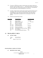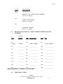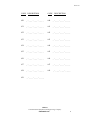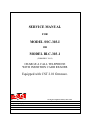
1
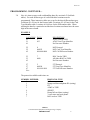
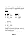
SSC OR BLC-303-1 (306-I)-CST2.01-ISSUE 4.0
SERVICE MANUAL
FOR
MODEL SSC-303-I
OR
MODEL BLC-303-1
(FORMERLY 306-I)
CHARGE A CALL TELEPHONE
WITH INSERTION CARD READER
Equipped with CST 2.01 firmware.
Serving the Telephone Industry Since 1930
Communication Equipment
& Engineering Company
519 W South Park Street
Okeechobee, FL 34972
Voice: 863-357-0798
Fax: 863-357-0006
Issue 4.0
IMPORTANT INFORMATION
FOR
CUSTOMER
Please fill in before you continue.
The following information is necessary when calling CEECO for assistance.
MODEL NUMBER
MODEL SSC OR BLC-303-I EQUIPPED
WITH CST2.01 FIRMWARE
(FORMERLY 306-I)
SERIAL NUMBER
DATE MANUFACTURED
LOCATION INSTALLED
For us to better serve you, please have this information available when calling for technical
support.
CEECO
Communication Equipment & Engineering Company
519 W South Park Street
Okeechobee, FL 34972
863-357-0798- telephone
863-357-0006- facsimile
[email protected]
www.ceeco.net
CEECO
Communication Equipment and Engineering Company
PROPRIETARY
2
Issue 4.0
TABLE OF CONTENTS
SECTION
PAGE
1.0
INTRODUCTION............................................................................................................................ 4
2.0
GENERAL........................................................................................................................................ 4
3.0
PROGRAMMING ........................................................................................................................... 5
PROGRAMMING CONTINUED… ............................................................................................... 6
PROGRAMMING CONTINUED................................................................................................... 7
PROGRAMMING CONTINUED................................................................................................... 8
PROGRAMMING CONTINUED................................................................................................... 8
4.0
PROGRAMMING TABLES........................................................................................................... 9
PROGRAMMING TABLES CONTINUED ................................................................................ 10
PROGRAMMING TABLES CONTINUED ................................................................................ 12
5.0
OPERATION ................................................................................................................................. 13
6.0
CARD CALLING........................................................................................................................... 13
7.0
SPECIFICATIONS........................................................................................................................ 14
8.0
PARTS LIST .................................................................................................................................. 15
9.0
RECOMMENDED TOOLS AND TEST EQUIPMENT............................................................ 15
10.0
INSTALLATION NOTES AND ASSEMBLY INSTRUCTIONS............................................. 16
11.0
TROUBLESHOOTING ................................................................................................................ 17
TROUBLESHOOTING CONTINUED ....................................................................................... 18
12.0
FCC NOTICE................................................................................................................................ 19
13.0
REPAIR AND RETURN INFORMATION ............................................................................... 20
14.0
WARRANTY POLICY ................................................................................................................ 21
15.0
LOCATION OF PROGRAMMING JUMPERS ...................................................................... 22
CEECO
Communication Equipment and Engineering Company
PROPRIETARY
3
Issue 4.0
1.0
INTRODUCTION
The practices in this manual provide installation and maintenance information for the
CEECO Model SSC OR BLC-303-I Charge-A-Call Telephone with Insertion Card
Reader (formerly 306-I) and firmware CST2.01.
The information in this manual is subject to change without notification.
For information not included in this manual, please call or write:
CEECO
Customer Service
519 W South Park Street
Okeechobee, FL 34972
863-357-0798- telephone
863-357-0006- facsimile
[email protected]
www.ceeco.net
2.0
GENERAL
The CEECO Model 303-I Charge-A-Call Telephone is a microprocessor-based, line
powered instrument designed to read the information encoded on the magnetic strip of
any ABA Track-2 credit card, and transmit the data via DTMF tones. This model is
compatible with the AT&T/BOC, TSPS "Calling Card Service" (CCS) systems and the
Southlake Technologies or Summa-Four Call Processors. Software protocol must be
specified when ordering.
NOTE: Before installing the phone, please read; Section 10.0 Installation Notes.
CEECO
Communication Equipment and Engineering Company
PROPRIETARY
4
Issue 4.0
3.0
PROGRAMMING
3.1
Using a security tool, remove the backplate and locate the Printed Circuit Board.
Locate the two plastic mini-jumpers on the Printed Circuit Board. With the phone
on hook, place the two mini-jumpers in the "ON" position, as depicted in the
diagram on the last page of this manual.
3.2
Take the phone off hook. if you are programming the phone for the first time,
clear all field programmable memory by dialing #97.
3.3
Each location is accessed by dialing #XX, where XX is a two (2) digit code from
00 to 97. The previous contents of the location are automatically erased when the
location is dialed.
3.4
In location #18 enter the default call processor number. If the dial-up number is a
C.O. speed dial number, enter the "*" key in place of the "#" (i.e. to send 22#,
enter 22*). Leave this location blank if no call processor is used.
3.5
In location #19 enter the P.B.X access code, if any (i.e. 9).
3.6
In location #20, enter the phone I.D. (up to 11 digits). Required only for use with
Call Processors.
3.7
If Charge-A-Call restrictions by the phone are necessary, enter the allowable
numbers in the free call index (location #70 - #79).
EXAMPLE:
#70
#71
#72
#73
#74
#75
(NOTE: "-" Shown for clarity only.)
0-***-***-**** (allows all 0-, 0+ calls)
*11 (allows 911, 411, 611, etc.)
1-555-1212
1-***-555-1212
1-800-***-****
950-****-**** (allows all 950 exchange numbers)
NOTE: Each location is up to eleven digits in length. To allow additional digits
to be dialed, fill the remaining spaces with "*"s.
EXAMPLE: #75 950-**** will not allow digits to be dialed after reaching the
OCC. 950-****-**** will allow unlimited dialing after the OCC call has been
completed.
To disable all phone implemented call restrictions enter eleven "*"s in one of the
free call index locations.
CEECO
Communication Equipment and Engineering Company
PROPRIETARY
5
Issue 4.0
PROGRAMMING CONTINUED…
3.8
Now it is time to enter credit card handling data (See section 4.03 for blank
tables.). For each different type of credit card three locations must be
programmed. Three interactive tables are set up for the three different data types.
Locations #21-#29 are for the Protocol table. Locations #51-#59 are for the Card
Type Identifier table. Locations #61-#69 are for the POP number table. When
entering the data for a particular card the three locations used must have the same
digit in the ones column.
EXAMPLE:
LOCATION DATA
21
3
51
855
61
DESCRIPTION
AT&T Card to TSPS
AT&T Card Type Identifier.
No Processor Number.
22
52
62
0
660032
888-888-8888
MCI Protocol.
MCI Card Type Identifier.
MCI Call Processor Number.
23
53
63
7
6600
BOC Card to TSPS.
All Other BOCS to TSPS.
No Processor Number.
27
57
67
Etc...
2
660030
999-999-9999
ITT Protocol.
ITT Card Type Identifier.
ITT Call Processor Number.
The protocols available at this time are:
NUMBER ENTERED
0
1
2
3
4
5
6
7
PROTOCOL TYPE
MCI
Dump card data and phone ID. (testing)
ITT
AT&T to TSPS
SPRINT
Dump full card data. (testing)
3 error tones and reset phone.
BOC cards to TSPS.
CEECO
Communication Equipment and Engineering Company
PROPRIETARY
6
Issue 4.0
PROGRAMMING CONTINUED
Be sure to record the Protocol numbers entered from the previous page into the Protocol
table locations #21-#29 on page 10 for future reference. Also record the Card Type
Identifiers in the Card Type Identifier Table locations #51-#59. When entering numbers
in the Card Type Identifier table, if you are using identifiers that have similar beginning
digits, you must enter them according to their digit length. Place the longer length
numbers first. Record the POP numbers in the POP Table locations #61- #69.
EXAMPLES:
WRONG
WRONG
DIGIT LENGTH
Loc. |1|2|3|4|5|6|7|
#51
|8|5|5| | | | |
AT&T
#52
|6|6|0|0| | | |
ALL BOCS
#53
|6|6|0|0|3|0| | ITT
#54
|6|6|0|0|3|2| | MCI
#55 |6|6|0|0|1|5| | WIS BELL
Similar beginning digits.
DIGIT LENGTH
|1|2|3|4|5|6|7|
|8|5|5| | | | |
AT&T
|6|6|0|0|3|0| | ITT
|6|6|0|0|3|2| | MCI
|6|6|0|0| | | |
ALL BOCS
|6|6|0|0|1|5| | WIS BELL
Similar beginning digits.
RIGHT
DIGIT LENGTH
Loc. |1|2|3|4|5|6|7|
#51
|8|5|5| | | | |
AT&T
#52
|6|6|0|0|3|0| | ITT
#53
|6|6|0|0|3|2| | MCI
#54 |6|6|0|0|1|5| | WIS BELL
#55
|6|6|0|0| | | |
ALL BOCS
Similar beginning digits.
The first example is wrong because location 52 would cause the phone to match ITT,
MCI and WIS BELL with the protocol for all BOCS. The second example is wrong
because location 54 would cause the phone to match a WIS BELL card to the protocol
for all other BOC cards. Notice, in the last example, that even though the AT&T number,
in location 51, is shorter then the numbers that follow it the right protocol is selected
because the beginning digits are different.
Be sure that you adjust the other tables if you have already entered data in them.
CEECO
Communication Equipment and Engineering Company
PROPRIETARY
7
Issue 4.0
PROGRAMMING CONTINUED
3.9
Location #00 is the option number, by entering 0 or 1 into each of the 8 digit
locations below, the phone is customized to each particular installation.
LOCATION #00:
Digit 1:
0
No incoming calls allowed.
1
Incoming calls allowed.
Digit 2:
0
Call restrictions are in effect. (#70-#79 only.)
1
No call restrictions.
Digit 3:
0
All calling cards are allowed.
1
All calling cards are blocked.
Digit 4:
0
Memory inspection disabled.
1
Memory inspection enabled.
Digit 5:
0
Send expiration date of Bank Cards mm/yr (i.e. AT&T as long distance carrier).
1
Do not send expiration date of Bank Cards (i.e. MCI as long distance carrier).
Digit 6:
0
Send only credit card numbers.
1
Send all credit card information on Track 2 (for use with a Call Processor).
Digit 7:
0
Always 0 for Insertion type card reader.
Digit 8:
0
Wide dial tone detect window.
1
Narrow dial tone detect window.
3.10
Locations #31-#50 are for the Speed Dial Table. Up to eleven digits may be
entered in each location. Enter # followed by the location number and the number
to be speed dialed from the keypad.
3.11
When programming is completed, place the two mini-jumpers in the "OFF"
position, replace and secure the backplate, and place the phone on hook.
PROGRAMMING CONTINUED
CEECO
Communication Equipment and Engineering Company
PROPRIETARY
8
Issue 4.0
3.12
If you have a DTMF test set and you want to inspect any memory location you
must have location #00 digit 4 set to a "1". Then simply enter the # key followed
by the two digit code for the memory location to be inspected. The information
stored in that memory location should appear on your test set.
3.13
To change a single memory location, place the phone on hook and place the two
mini-jumpers in the "ON" position. Take the phone off hook, enter # plus the
corresponding two digit code for that memory location, and enter the new
numbers. Hang the phone up and place the two mini-jumpers in the "OFF"
position.
3.14
Summary of programming locations:
LOCATION
#00
#18
#19
#20
#21 - #29
#30 - #49
#51 - #59
#61 - #69
#70 - #79
#97
4.0
DESCRIPTION
SAMPLE ENTRY
Option Number
Default Call Processor
P.B.X. Access Code
Phone I.D. Number
Card Protocol Code
Speed Dial Numbers
Card Type Identifiers
POP Numbers For Each Card Type
Free Call Index
Clear All Programmable Memory
10110000
555-1212
9
1234567
3
444-4444
660015
950-5555
911
N/A
PROGRAMMING TABLES
4.0
OPTION TABLE
CODE
#00
DESCRIPTION
_________
Digit 1 2 3 4 5 6 7 8 9
PROGRAMMING TABLES CONTINUED
4.2
IDENTIFICATION TABLE
CEECO
Communication Equipment and Engineering Company
PROPRIETARY
9
Issue 4.0
CODE
DESCRIPTION
#18
_-___-___-____
DEFAULT CALL PROCESSOR NUMBER
(enter 1 to 11 digits)
#19
_-___-___-____
PABX ACCESS CODE
(enter 1 to 11 digits)
#20
_-___-___-____
PHONE ID NUMBER
(enter 7 to 11 digits)
4.3
PROTOCOL SELECTION, CARD TYPE IDENTIFIERS AND POP
NUMBERS
Code
Protocol
Selected
#21 _
(1 digit)
Code Card type ID
Code POP
_________
(notes)
#51
_____________
(up to 11 digits)
#61
______________
(up to 11 digits)
#22 _
_________
#52
_____________
#62
______________
#23 _
_________
#53
_____________
#63
______________
#24 _
_________
#54
_____________
#64
______________
#25 _
_________
#55
_____________
#65
______________
#26 _
_________
#56
_____________
#66
______________
#27 _
_________
#57
_____________
#67
______________
#28 _
_________
#58
_____________
#68
______________
#29 _
_________
#59
_____________
#69
______________
PROGRAMMING TABLES CONTINUED
4.4
SPEED DIAL TABLE
CEECO
Communication Equipment and Engineering Company
PROPRIETARY
10
Issue 4.0
CODE DESCRIPTION
CODE
DESCRIPTION
#30
_-___-___-____
#40
_-___-___-____
#31
_-___-___-____
#41
_-___-___-____
#32
_-___-___-____
#42
_-___-___-____
#33
_-___-___-____
#43
_-___-___-____
#34
_-___-___-____
#44
_-___-___-____
#35
_-___-___-____
#45
_-___-___-____
#36
_-___-___-____
#46
_-___-___-____
#37
_-___-___-____
#47
_-___-___-____
#38
_-___-___-____
#49
_-___-___-____
#39
_-___-___-____
CEECO
Communication Equipment and Engineering Company
PROPRIETARY
11
Issue 4.0
PROGRAMMING TABLES CONTINUED
4.5
FREE CALL TABLE
CODE DESCRIPTION
CODE DESCRIPTION
#70
_-___-___-____
#75
_-___-___-____
#71
_-___-___-____
#76
_-___-___-____
#72
_-___-___-____
#77
_-___-___-____
#73
_-___-___-____
#78
_-___-___-____
#74
_-___-___-____
#79
_-___-___-____
EXAMPLES OF CALL RESTRICTIONS/ALLOWED CALLS
(950-***-****-* allows access to 950 exchange numbers)
(1-800-***-****)
1-***-555-1212 interlata directory assistance)
(1-555-1212 intralata directory assistance)
(*11 allows 411, 911, 011, etc.)
(0-***-*-**-**** allows all 0-,0+,and calling cards)
CEECO
Communication Equipment and Engineering Company
PROPRIETARY
12
Issue 4.0
5.0
OPERATION
5.1
The phone is taken off hook.
5.2
If location #19 contains a number, the phone will wait for dial tone, then dial the
number entered in location #19. This is the PABX Access Number. If you do not
want a PABX number dialed then leave location #19 blank.
5.3
Three modes of operation exist at this time:
a.
b.
c.
6.0
Dial a free call; 911, 411 only if number resides in free-call table (4.05)
Dial 0+ the number desired, wait for the tone, then insert/withdraw credit
card.
Enter a Help Selection only if your call processor offers this feature.
CARD CALLING
6.1
If a valid Credit Card read was performed, a verifier beep will be heard. The
phone will determine which type of card was read and what Protocol to use.
6.2
If AT&T cards are programmed to be blocked, 3 error tones will be heard and the
phone will reset itself for another call.
6.3
If the call is to go to TSPS, the phone will wait for the user to dial a 0+ number.
At the bong tone, the phone will send the card data.
6.4
If the call is to go to the Call Processor, the phone will dial the Call Processor.
When the Call Processor acknowledges, the phone will send the phone I.D. and
credit card information. The phone is now open. (Card reader on, keypad on,
transmitter on, no call restrictions in effect.)
6.5
FREE CALLS. If the user attempts to dial a call not programmed in the free call
index (call restrictions enabled), the phone will give three warning tones to the
user, go on hook, and reset for another call attempt.
CEECO
Communication Equipment and Engineering Company
PROPRIETARY
13
Issue 4.0
7.0
SPECIFICATIONS
INPUT POWER
C.O. Line powered
LOOP CURRENT
23 mA min., 80 mA max.
IMPEDANCE
600 ohms
SIGNALING
DTMF, 70ms Tone, 70 ms Spacing
OUTPUT
-4 to -6 dBm
HEARING AID COMPATIBLE
Meets EIA standards
ENVIRONMENTAL
Temperature: 0°C to 50°C
Humidity: 20% to 90% non-condensing
RINGER EQUIVALENCY
0.8A
PROGRAMMING
Via unit keypad
TELEPHONE PANEL
Brushed 16-gauge stainless steel
DIMENSIONS
5∀ wide x 10 3/4∀ high x 5½” deep
Handset on hook
MOUNTING
Vertical surface mount
MEMORY RETENTION
Lithium battery, long life
FCC REGISTRATION
BW88T7-13823-TE-T
UL LISTED NO.
6OF5
TYPE JACK
RJ11C
CARD READER
Protocol
Capacity
Speed
Life
Insertion Type, Read Only
ABA Track-2, 1S02
40 characters
8-150 cm/sec
500,000 reads min.
POP PROTOCOLS SUPPORTED
Southlake Technologies
Summa-Four
AT&T "Calling Card System" (CCS)
MCI
ITT
TSPS
SPRINT
BOC Cards to TSPS
Custom Programming on Special order
CEECO
Communication Equipment and Engineering Company
PROPRIETARY
14
Issue 4.0
8.0
9.0
PARTS LIST
DESCRIPTION
Hookswitch Cradle
Tongue & Bracket Assembly
Handset w/Armored Cord
Network
Network Cable Assembly
Ringer
MCRK-2 PC Board Assembly
Chrome ANS Keypad
Keypad Cable
Modular Line Cord
#10-32 Security Screws (2 ea.)
Card Reader Assembly
Card Reader Cable
Instruction Card Kit
Number Window
Number Card
Backplate
Grommet
Modular Connector (RJ11C)
Handset Swivel
CTA Board
PART NO.
301-588
301-581
301-004
301-009
650-570
401-009
650-540
705-110
700-005
301-018
321-016
306-600
306-034
301-030
301-039
301-040
301-051
301-052
301-054
308-016
917-006
OPTIONAL:
Security Tool
GTE Logo
301-037
301-041
RECOMMENDED TOOLS AND TEST EQUIPMENT
Volt/Ohm Meter
3/8∀ Nut Driver
Security Tool, CEECO Part Number 301-037
Flat Blade Screw Driver
DTMF Test Set
CEECO
Communication Equipment and Engineering Company
PROPRIETARY
15
Issue 4.0
10.0 INSTALLATION NOTES AND ASSEMBLY INSTRUCTIONS
10.1
The use of a gas tube station protector is recommended. The station ground
should not exceed 50 ohms.
10.2
To connect the phone to a phone line, plug the modular line cord from the phone
unit into any RJ11C receptacle.
10.3
To access the inside of the phone for programming or service, remove the security
screws on the sides and loosen the locking rod on the front using a 301-037
Security Tool. Slowly lift the cover, taking care not to damage the cables
connecting the keypad and card reader to the MCRK-2 PC Board inside the
phone.
10.4
The cover assembly may be separated from the base by disconnecting one end of
each cable from the MCRK-2 PC Board.
10.5
When servicing the MCRK-2 board, be sure the board does not contact metal
parts, otherwise permanent damage may occur to the board.
***** WARNING *****
A.
Never install telephone wiring during a lightning storm.
B.
Never install telephone jacks in wet locations unless the
jack is specifically designed for wet locations.
C.
Never touch uninsulated telephone wires or terminals
unless the telephone line has been disconnected at the
network interface.
D.
Use caution when installing or modifying telephone lines.
CEECO
Communication Equipment and Engineering Company
PROPRIETARY
16
Issue 4.0
11.0 TROUBLESHOOTING
Always visually check the phone for loose or shorted wires, damaged terminals or
damaged parts.
PROBLEM: NO DIAL TONE AND/OR MCKR-2 CARD DOES NOT FUNCTION
POSSIBLE CAUSE:
LINE CORD
RJ11C CONNECTOR
MCRK-2 CARD
NETWORK
NETWORK CABLE ASSY
HOOKSWITCH CABLE ASSY
HOOKSWITCH ASSY
MICRO-PROCESSOR
HANDSET
PROBLEM: DIAL TONE IS DISTORTED
POSSIBLE CAUSE:
NETWORK CABLE ASSY
HOOKSWITCH CABLE ASSY
HOOKSWITCH ASSY
MCRK-2 CARD
NETWORK
HANDSET
PROBLEM: PHONE DOES NOT READ CARD
POSSIBLE CAUSE:
CARD
DIRTY READ HEAD
CARD READER
CARD READER CABLE
MCRK-2 CARD
PROBLEM: TRANSMITTER DOES NOT TURN ON
POSSIBLE CAUSE:
HANDSET
MCRK-2 CARD
NETWORK CABLE ASSY
NETWORK
CEECO
Communication Equipment and Engineering Company
PROPRIETARY
17
Issue 4.0
TROUBLESHOOTING CONTINUED
PROBLEM: TRANSMITTER DOES NOT TURN ON FOR INCOMING CALLS
POSSIBLE CAUSE:
IMPROPER OPTION NUMBER, CHANGE FIELD #00 DIGIT 1 TO A "1"
MCRK-2 CARD
PROBLEM: KEYPAD DOES NOT OPERATE PROPERLY
POSSIBLE CAUSE:
KEYPAD CABLE ASSY.
KEYPAD
MCRK-2 CARD
PROBLEM: PHONE DOES NOT RECOGNIZE CALL PROCESSOR TONE OR BONG TONE
POSSIBLE CAUSE:
MCRK-2 CARD
NETWORK
NETWORK CABLE ASSY.
PROBLEM: LOOSES MEMORY CONTENTS AFTER EXTENDED PERIODS OF NO USE
POSSIBLE CAUSE:
LITHIUM BATTERY
PROBLEM: PHONE CANNOT BE PROGRAMMED
POSSIBLE CAUSE:
MINI-JUMPERS MISPLACED
MEMORY CHIP
MCRK-2 CARD
KEYPAD
KEYPAD CABLE ASSY.
PROBLEM: RINGER DOES NOT OPERATE
POSSIBLE CAUSE:
RINGER
NETWORK
CEECO
Communication Equipment and Engineering Company
PROPRIETARY
18
Issue 4.0
12.0 FCC NOTICE
12.1
FCC REGISTRATION AND REPAIR INFORMATION
Your new telephone has been registered with the Federal Communication
Commission (FCC) in accordance with Part 68 of it's rules. The FCC requires that
you be advised of certain requirements involving the use of this telephone.
12.2
CONNECTION AND USE WITH THE NATIONWIDE TELEPHONE
NETWORK.
The FCC requires that you connect this telephone to the Nationwide Telephone
Network through a registered jack provided by the telephone company in your
area. This jack is a modular outlet which you can order from your local telephone
company.
12.3
NOTIFICATION TO THE TELEPHONE COMPANY
Before connecting this telephone, the FCC requires that you notify your local
telephone company business office. The number is in the front of your phone
book.
Tell them:
The "line" to which you will connect the telephone (that is, your phone number),
the telephone's FCC registration number and ringer equivalence number. These
numbers are listed in section 7.0
The FCC further requires that you notify your local telephone company when
permanently disconnecting this telephone.
CEECO
Communication Equipment and Engineering Company
PROPRIETARY
19
Issue 4.0
13.0 REPAIR AND RETURN INFORMATION
13.1
WARRANTY REPAIR
Any device returned requiring warranty service, repair or credit must be
accompanied with a "Return Material Authorization" (RMA) FORM. It must
include: return shipping instructions, original purchase order number and special
marking instruction. A description of the trouble observed must be attached to
the defective unit. This information must be inside the shipping container.
13.2
DIRECT ALL INQUIRES TO:
CEECO
Repair Department
863-357-0798- telephone
863-357-0006- facsimile
[email protected]
www.ceeco.net
13.3
NON-WARRANTY REPAIR
CEECO will repair equipment out of warranty for a set charge plus parts. The
customer must pay the shipping costs for both directions.
13.4
RETURN FOR CREDIT
Material may be returned for credit only with prior approval. Material authorized
for return is subject to a 20% restocking charge based on the manufacturers list
price. Return Material Authorization must be requested no later than 30 days
after original shipment.
13.5
EXCHANGE POLICY
If a replacement unit is required it will be shipped in the most expedient manner
consistent with the urgency of the situation. Please contact "Customer Service"
for instructions regarding exchange of modules or printed circuit boards.
CEECO
Communication Equipment and Engineering Company
PROPRIETARY
20
Issue 4.0
14.0 WARRANTY POLICY
14.1
GENERAL
CEECO products are guaranteed to be free of defects in material and
workmanship for a period of 365 days from the date of original purchase.
CEECO’s obligation under this warranty is limited to repair or replacement of any
part found to be defective by CEECO. Under no circumstances shall CEECO be
liable for loss, damage, cost of repair, or consequential damages of any kind
which have been caused by neglect, abuse, acts of GOD or improper of
equipment.
14.2
PRINTED CIRCUIT BOARDS
Printed circuit boards should not be field repaired. If a unit is found to be faulty,
replace it with another unit and return the faulty unit to CEECO for repair.
Modifications by anyone other than CEECO will void the warranty.
CEECO
Communication Equipment and Engineering Company
PROPRIETARY
21
Issue 4.0
15.0 LOCATION OF PROGRAMMING JUMPERS
Locate the mini jumpers
on the corner of the PCB.
ON
F
OF
Move the mini jumpers to
the ON position BEFORE
going off-hook.
When programming is
completed, move the mini
jumpers to the OFF
position.
ON
F
OF
ON
F
OF
NOTE:
Do not leave the mini jumpers in the ON position,
this will decrease battery life.
CEECO
Communication Equipment and Engineering Company
PROPRIETARY
22