1
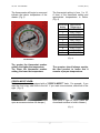
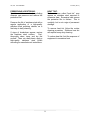
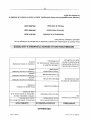
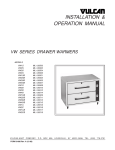
 INSTALLATION &
OPERATION MANUAL
VW & VSL SERIES DRAWER WARMERS
VCW1, VCW2 CHIP WARMERS
MODELS:
CHIP WARMERS:
VCW1
VCW2
ML-138038
ML-138041
DRAWER WARMERS: CAFÉ’: VW1S
VW2S
VW3S
VW4S
ML-126500
ML-126502
ML-126504
ML-126506
CAFE’ BUILT-IN:
VW1SB
VW2SB
VW3SB
VW4SB
ML-126501
ML-126503
ML-126505
ML-126507
SLIMLINE LOW PROFILE:
SLIMLINE BUILT-IN:
VW1C
VW2C
VSL1
VSL2
ML-126516
ML-126518
VW1CB
VW2CB
ML-126508
ML-126510
ML-126512
ML-126514
VW1DB
VW2DB
VW3DB
VW4DB
R-SERIES:
VW1D
VW2D
VW3D
VW4D
ML-126517
ML-126518
R-SERIES BUILT-IN:
ML-126509
ML-126511
ML-126513
ML-126515
VULCAN-HART
3600 NORTH POINT BLVD.
DIVISION OF ITW FOOD EQUIPMENT GROUP, LLC
BALTIMORE, MD 21222
www.vulcanequipment.com
Vulcan ©2015 All Rights Reserved
F-31086 (02-15)
VW, VSL & VCW SERIES
F-31086 (02-15)
IMPORTANT FOR YOUR SAFETY
THIS MANUAL HAS BEEN PREPARED FOR PERSONNEL QUALIFIED TO INSTALL
ELECTRICAL EQUIPMENT, WHO SHOULD PERFORM THE INITIAL FIELD STARTUP AND ADJUSTMENTS OF THE EQUIPMENT COVERED BY THIS MANUAL.
FOR YOUR SAFETY
DO NOT STORE OR USE GASOLINE OR OTHER
FLAMMABLE VAPORS OR LIQUIDS IN THE
VICINITYOF THIS OR ANY OTHER APPLIANCE.
Improper installation, adjustment,
alteration, service, or maintenance can
cause property damage, injury, or death.
Read the installation, operating and
maintenance instructions thoroughly
before installing or servicing equipment.
IN THE EVENT OF A POWER FAILURE,
DO NOT ATTEMPT TO OPERATE THIS DEVICE.
1
VW, VSL & VCW SERIES
F-31086 (02-15)
TABLE OF CONTENTS
IMPORTANT FOR YOUR SAFETY . . . . . . . . . . . . . . . . . . . . . . . . . . . . . . . . . . . . . . . . 1
GENERAL . . . . . . . . . . . . . . . . . . . . . . . . . . . . . . . . . . . . . . . . . . . . . . . . . . . . . . . . . . . 3
INTRODUCTION . . . . . . . . . . . . . . . . . . . . . . . . . . . . . . . . . . . . . . . . . . . . . . . . . 3
INSTALLATION . . . . . . . . . . . . . . . . . . . . . . . . . . . . . . . . . . . . . . . . . . . . . . . . . . 3
TRIM KIT INSTALLATION . . . . . . . . . . . . . . . . . . . . . . . . . . . . . . . . . . . . . . . . . . 4
ELECTRICAL REQUIREMENTS . . . . . . . . . . . . . . . . . . . . . . . . . . . . . . . . . . . . . 5
OPERATION . . . . . . . . . . . . . . . . . . . . . . . . . . . . . . . . . . . . . . . . . . . . . . . . . . . . . . . . . 6
CONTROLS . . . . . . . . . . . . . . . . . . . . . . . . . . . . . . . . . . . . . . . . . . . . . . . . . . . . . 6
OPERATING INSTRUCTIONS . . . . . . . . . . . . . . . . . . . . . . . . . . . . . . . . . . . . . . 6
THERMOMETER . . . . . . . . . . . . . . . . . . . . . . . . . . . . . . . . . . . . . . . . . . . . . . . . .7
THERMOSTAT SETTING. . . . . . . . . . . . . . . . . . . . . . . . . . . . . . . . . . . . . . . . . . .7
CLEANING . . . . . . . . . . . . . . . . . . . . . . . . . . . . . . . . . . . . . . . . . . . . . . . . . . . . . . 8
DAILY . . . . . . . . . . . . . . . . . . . . . . . . . . . . . . . . . . . . . . . . . . . . . . . . . . . 8
HEAVY-DUTY CLEANING . . . . . . . . . . . . . . . . . . . . . . . . . . . . . . . . 8
STAINLESS STEEL CARE . . . . . . . . . . . . . . . . . . . . . . . . . . . . . . . . . . . . . . . . . 8
PRESERVING & RESTORING . . . . . . . . . . . . . . . . . . . . . . . . . . . . . . . . . . . . . . 9
HEAT TINT . . . . . . . . . . . . . . . . . . . . . . . . . . . . . . . . . . . . . . . . . . . . . . . . . 9
TROUBLESHOOTING . . . . . . . . . . . . . . . . . . . . . . . . . . . . . . . . . . . . . . . . . . . . . . . . . 10
SERVICE & PARTS INFORMATION . . . . . . . . . . . . . . . . . . . . . . . . . . . . . . . . . . . . . . 10
2
VW, VSL & VCW SERIES
F-31086 (02-15)
GENERAL
INTRODUCTION
It is suggested that you thoroughly read
this entire manual and carefully follow all
of the instructions provided.
Vulcan-Hart Drawer Warmers and Chip
Warmers are produced with quality
workmanship and material.
Proper
installation, usage, and maintenance of
your warmer will result in many years of
satisfactory performance.
The VW Series Drawer Warmers
provide an efficient means of holding a
variety of prepared hot food products at
proper temperatures until serving.
INSTALLATION
3.
Before installing, verify that the electrical
service agrees with the specifications on
the rating plate located on the lower
back corner of the warmer. If the supply
and equipment requirements do not
agree, do not proceed with unpacking
and installation. Contact your VulcanHart Customer Service Department
immediately.
4.
5.
6.
7.
UNPACKING:
The Warmer was inspected before
leaving the factory. The transportation
company assumes full responsibility for
safe delivery upon acceptance of the
shipment. Immediately after unpacking,
check for possible shipping damage to
the warmer.
Remove legs from drawer of
warmer.
Secure legs to the bottom of
warmer by screwing legs into the
holes provided.
Remove any and all packaging
materials in drawers.
Peel off vinyl protection film.
Thoroughly clean the warmer as
described in the cleaning instructions.
CLEANING:
The warmer should be thoroughly
cleaned prior to putting into service.
Use a mild soap and water solution to
clean the interior drawer inserts of the
unit. Never use harsh chemicals or
abrasive pads to clean the unit.
If the warmer is found to be
damaged,
save
the
packaging
material and contact the carrier
within 15 days of delivery.
LOCATION:
For efficient warmer operation, choose a
location that will provide easy loading
and unloading without interfering with
the final assembly of food orders.
Carefully unpack warmer and place in a
work accessible area.
1.
Remove banding holding the
carton to the pallet.
2.
Carefully remove warmer from
carton and place on floor or table.
The installation location must allow
adequate clearances for servicing and
proper operation.
3
VW, VSL & VCW SERIES
F-31086 (02-15)
TRIM KIT INSTALLATION
3.
Models: VW1SB, VW2SB, VW3SB,
VW4SB, VW1CB, VW2CB, VW1DB,
VW2DB, VW3DB, VW4DB
Built-in Drawer Warmers come with a
“trim kit.” Follow the general installation
instructions in the “Installation &
Operation
Manual”
regarding
Unpacking, Electrical Requirements,
Cleaning, and Removal of Vinyl
Protection Film.
1.
Remove the drawer assemblies
from the cabinet.
a.
Open drawer to full extension.
b.
Lift up drawer and pull out
slightly.
MOUNTING HOLES
4.
Using #8 Tech Screws that
are included, fasten the four
screws into the mounting holes.
The screws are self-tapping and no
pilot holes are necessary.
5.
c.
Trim Kit has 4 mounting holes.
There are two holes on the
bottom and two holes on the top.
Tilt down drawer and pull out.
Connect Drawer Warmer to
electrical power supply per your
local electrical code.
Please
refer
to
Electrical
Requirements in the Installation &
Operation Manual.”
2.
Place Trim Kit flush with the front
of the Drawer Warmer.
4
6.
Slide/install
Warmer
wall/cabinet opening.
into
7.
Reinstall drawer assemblies into
warmer – Top to Bottom.
VW, VSL & VCW SERIES
F-31086 (02-15)
ELECTRICAL REQUIREMENTS
:
All warmers are
equipped with a three-prong plug. It
is imperative that this plug must be
connected into a properly grounded
three-prong receptacle.
If the
receptacle is not the proper
grounding
type,
contact
an
electrician.
Do not remove the
grounding prong from this plug.
ELECTRICAL CODES & STANDARDS:
The warmer must
accordance with:
be
installed
in
In the United States of America:
1.
State and Local Codes.
2.
National Electrical Code, ANSI/
NFPA-70 (latest edition.) Copies
may be obtained from:
The
National
Fire
Protection
Association, Batterymarch Park,
Quincy, MA 02269.
Verify that the power source
matches the Serial Data Plate located
on the lower back corner of the
warmer and the plug configuration
before the connection is made. (Fig. 1)
In Canada:
1.
Local Codes.
2.
Canadian Electrical Code, CSA
C22.1 (latest edition.) Copies
may be obtained from:
The
Canadian Standard Association,
178 Rexcale Blvd., Etobicoke,
Ontario, Canada M9W 1R3.
SERIAL DATA PLATE
ELECTRICAL CONNECTIONS:
The warmer is factory wired for either
110/120 volt or 208/240 volt, single
phase operation.
All 110/120 volt
warmers are equipped with a 8 foot cord
and NEMA 5-15 plug as standard
equipment. All 208/240 volt warmers
are equipped with a 8 foot cord and
NEMA 6-15 plug.
Refer to wiring
diagrams in the back of this manual.
Fig. 1
The cord and plug supplied is a suitable
durable cord with a molded three-prong
plug, and is provided with a proper
strain relief.
5
VW, VSL & VCW SERIES
F-31086 (02-15)
OPERATION
POWER LIGHT
CONTROLS
The Warmer and its
parts are hot. Be very careful when
operating, cleaning, or servicing the
warmer.
The warmer Control Panel contains an
operating indicator light and a full range
thermostat. (Fig.2)
THERMOSTAT DIAL:
The thermostat also acts as the On/Off
switch to the warmer system. Turning
the thermostat counter clock-wise until it
stops will turn the warmer off.
POWER LIGHT:
The power light turns on and off as the
heating elements cycle.
THERMOSTAT DIAL
(Fig. 2)
THERMOMETER
It is recommended that prior to placing the warmer into operation that it be preheated at the highest temperature setting for a period of 30 to 45 minutes
.
OPERATING INSTRUCTIONS
Begin by turning the thermostat dial to
the number 5. This will cause the
heating element to start heating. When
this occurs, the red operating indicator
light will illuminate. This red light will
stay on as long as the heating element
is engaged. Once the predetermined
temperature is achieved, the heating
element will begin to cycle. During this
period, the red operating indicator light
will turn on and off as the heating
elements cycle.
The Warmer and its
parts are hot. Be very careful when
operating, cleaning, or servicing the
warmer.
Once the warmer has been connected
to the appropriate power source, the
warmer is ready for operation.
The warmers have one, two, three, or
four drawers depending on the model
purchased.
Each drawer has a
separate
thermostat
dial
and
thermometer.
6
VW, VSL & VCW SERIES
F-31086 (02-15)
The thermostat setting is from 1 to 10.
A chart of the thermostat setting and
approximate temperatures is below.
(Fig. 4)
The thermometer will begin to move and
indicate the interior temperature of the
drawer. (Fig. 3)
Thermostat
Setting
1 2 3 4 5 6 7 8 9 10 (Fig. 3)
Approximate Temperature 100⁰F (37⁰C) 110⁰F (43⁰C) 120⁰F (49⁰C) 130⁰F (54⁰C) 140⁰F (60⁰C) 150⁰F (66⁰C) 160⁰F (71⁰C) 170⁰F (77⁰C) 180⁰F (82⁰C) 190⁰F (88⁰C) (Fig. 4)
THERMOMETER
The greater the thermostat number
setting, the higher the temperature.
The lower the thermostat number
setting, the lower the temperature.
The operator should always monitor
the food product to insure that it
remains at proper temperatures.
CRISP & MOIST KNOB:
Each warmer drawer is equipped with a “CRISP & MOIST” knob. For example: If you
want the food crispy side knob to the left. If you want more moisture, slide knob to the
right. (Fig. 5)
Slide knob to right for moist (vents are
closed and moisture is held in drawer.)
Slide knob to left for crispy (vents are
open an excess moisture can escape.)
(Fig. 5)
7
VW, VSL & VCW SERIES
F-31086 (02-15)
CLEANING
electrical
cleaning.
power
Always
supply
STAINLESS STEEL CARE
unplug
before
CLEANING:
Stainless Steel contains 70 – 80% iron,
which will rust if not properly maintained.
Stainless Steel also contains 12 – 30%
chromium, which forms an invisible
passive, protective film that shields
against corrosion.
The Warmer and its
parts are hot. Be very careful when
operating, cleaning, or servicing the
warmer.
DAILY:
1.
Unplug electrical power supply.
2.
Allow warmer to cool before
cleaning.
3.
Clean drawers and the interior of
the warmer with a mild soap and
water.
Never use harsh
chemicals or abrasive pads to
clean the warmer.
4.
Rinse and dry with a soft dry
cloth.
5.
Clean the exterior of the warmer
with a clean damp cloth.
If the protective film remains intact, the
stainless steel will remain intact.
However, if the film is damaged, the
stainless steel can break down and rust.
PREVENTIVE CARE:
To prevent stainless steel breakdown, follow these steps:
HEAVY-DUTY CLEANING:
For heavy-duty cleaning, use warm
water, a degreaser, and a plastic,
stainless steel, or Scotch-Brite pad.
Never rub in a circular motion -- rub
gently in the direction of the steel grain.
Always rinse thoroughly
8
1.
Never use any metal tools,
scrapers, files, wire brushes,
or scouring pads (except for
stainless steel scouring pads,)
which will mar the surface.
2.
Never use steel wool – which
will leave behind particles that will
rust.
3.
Never use acid-based or
chloride containing cleaning
solutions – which will break
down the protective film.
4.
Never rub in a circular motion.
Always rub gently in the direction
of the steel grain.
5.
Never leave any food products
or salt on the surface. Many
foods are acidic. Salt contains
chloride
VW, VSL & VCW SERIES
F-31086 (02-15)
HEAT TINT:
Darkened areas, called “heat tint,” may
appear on stainless steel exposed to
excessive heat. Excessive heat causes
the protective film to thicken. This is
unsightly, but is not a sign of permanent
damage.
PRESERVING & RESTORING:
Special
stainless
steel
polishing
cleaners can preserve and restore the
protective film.
Preserve the life of stainless steel with a
regular application of a high-quality
stainless steel polishing cleaner, as a
final step to daily cleaning.
To remove heat tint, follow the routine
cleaning procedure. Stubborn heat tint
will require heavy-duty cleaning.
If signs of breakdown appear, restore
the stainless steel surface.
First,
thoroughly clean, rinse, and dry the
surface. Then, on a daily basis, apply a
high-quality stainless steel polish
according to manufacturer’s instructions.
To reduce heat tint, limit the exposure of
equipment to excessive heat.
9
VW, VSL & VCW SERIES
F-31086 (02-15)
TROUBLESHOOTING
SYMPTOMS
POSSIBLE CAUSES
Warmer not operating
REMEDY
Warmer not connected to
power source.
Connect cabinet to power
source.
No power
Check Circuit Breaker and/or
check GFCI switch on outlet.
GFCI or Ground Fault
Circuit Indicator tripped Moisture problem.
Shorted element
Pinched/damaged wire.
Damaged power cord.
Dry moisture problem.
Contact Authorized Service
Provider.
Contact Authorized Service
Provider.
Contact Authorized Service
Provider.
Warmer is connected to
power source,
Defective: heating element,
thermostat is turned on, thermometer, thermostat,
Contact Authorized Service
but warmer not heating
etc.
Provider.
SERVICE & PARTS INFORMATION
To obtain WARRANTY Service and Parts information concerning this model, contact
Vulcan-Hart at:
Customer Service
Technical Service
Service Parts
800-814-2028
866-688-5226
866-688-5226
When calling for service, have the model number and serial number available.
10
VW, VSL & VCW SERIES
F-31086 (02-15)
11
VW, VSL & VCW SERIES
F-31086 (02-15)
12