1
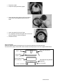
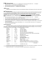
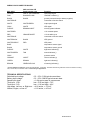
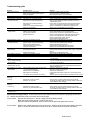
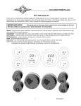
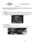
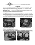
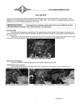
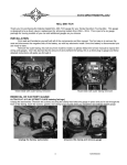
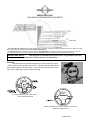
MODEL MCL-2002
TANK MOUNT SPEEDOMETER/TACHOMETER
*To avoid damage to motorcycle, please see Speedometer, Tachometer, and Status and Warning Indicators sections for details on locating
VSS, Tachometer, and indicator wires for most motorcycle applications
**For 2004+ HD utilizing the “Fat Bob” tank mount, please see our MCL-2004, it is designed as a direct plug-in gauge for these models. The
Check Engine indicator will not function using this gauge on 2004+ HD models due to the signal being fed through the ‘data bus’.
IMPORTANT NOTE!
This gauge has an odometer preset option that is only available for the first
100 miles (160km) of operation. See “preset odometer” for instructions.
Mounting:
The base system is universal enough to fit in either a new-style, clip-in
(1995 or newer) or into the older style, bolt-in. The rubber mounts with studs on
both sides are used for the bolt-in style. The L-brackets are used for the clip in
style. The ¼” ABS ring is used for Deuce mounting.
Mounting hardware for the bolt-in system
with a speedometer cable
Mounting hardware for the clip-in system with an electric
transmission speed sensor.
MAN# 650280:D
Mounting in a Dash with Cable Drive speedometer and rubber mounts
Dakota Digital Gauge
MCL-2002 (-R)
Foam Tape
Cable Drive Speed Sensor
With Mounting Hardware
Rubber Mounts
Factory Dash Panel
#8 Lock Washer
8-32 x ½” Nut
•
•
Remove the dash
Unbolt and unplug the factory gauge
•
Install the rubber mounts and foam tape around the new Dakota
Digital gauge. The tape should apply to the side of the gauge can
and be against the bottom of the bezel; this just fills the opening in
the dash.
•
Insert new gauge from front of dash
•
Use supplied lock washers and nuts to
attach the gauge to the factory dash
•
Now install the cable drive sender,
when required, as shown with the supplied
bracket and screws
•
Reinstall the dash
Mounting in a dash with factory electronic speed sensor
Dakota Digital Gauge
MCL-2002 (-R)
Factory Gasket
Factory Dash Panel
L-Bracket (supplied)
#8 Lock Washer
8-32 x ½” Screw
MAN# 650280:D
•
•
Remove the dash
Unclip and unplug the factory gauge
•
Insure that the rubber gasket is still in the dash or
remove from factory gauge and place back on
dash
•
•
Insert new gauge from front of dash
Use supplied L-brackets along with the 8-32 screws
and lock washers to secure the gauge
Reinstall the dash
•
Deuce mounting
NOTE: The supplied L-bracket mounting pieces are not used for this application and can be discarded
Since the Deuce gauge mounts from under the dash mounting requires use of the supplied ABS bracket.
Factory Dash
Panel
Mounting Tabs (cast in
dash)
Factory Bezel
Gasket
Dakota Digital Gauge
MCL-2002 (-R)
8-32 x ½” Screw
New ABS Mounting Bracket
(supplied)
#8 Lock Washer
MAN# 650280:D
•
Remove the dash
•
Unclip and unplug the factory gauge
•
Remove the rubber gasket from the factory gauge bezel.
•
Install gasket over the bezel of the Dakota Digital gauge.
The gasket doesn’t cover the entire bezel; there should
be some chrome showing when the gasket is installed.
•
Use the supplied ABS mounting ring to secure the gauge to the dash.
The ring has notches that align the gauge so it cannot be installed
upside down. The textured side of the ABS should be facing you
during install.
•
Snap the gauge into the dash starting with one tab in and then
working in a clockwise direction snapping the other two tabs in one at
a time. The tabs are tight so it takes a fair amount of pressure to
snap them in. Make sure they are seated under the tabs in the dash
once locked in.
•
Plug in the connector and reinstall the dash.
Wiring
POWER
Connect the red wire from the main harness to accessory power from the ignition switch.
Connect the white/red wire to constant battery power for the clock memory. The large red wire at the
ignition switch can be used for this.
*Never connect this to a battery charger alone. It needs to have a 12 volt battery connected to it. Battery chargers
have an unregulated voltage output that will cause the system to not operate properly.
GROUND
The black wire is the main ground for display system. A poor ground connection can cause improper or
erratic operation.
MAN# 650280:D
STATUS AND WARNING INDICATORS
The right turn, left turn, and high beam indicators are activated by 12
volts at their respective hook-up wires. The right turn signal wire is green,
the left turn signal wire is orange, and the high beam wire is purple. These
can be connected to the same wires that the indicator lights would be
connected to. The display system wire colors may not match the wire colors
in your electrical wire harness; consult a service manual to determine the
color code and location of any wires you cannot locate.
The neutral, low oil, and check engine indicators are activated by
ground at their respective hook-up wires. The check engine wire is pink, the
low oil wire is brown, and the neutral wire is white/green.
4
3
2
5
N
1
6
km/h
MPH
0
7
E
A
RPM
V
B
P
LOW VOLTAGE WARNING
When the voltage drops below the warning limit with the engine running, LO and your current voltage will be
displayed. (default warning limit is 11.0V)
SECURITY SYSTEM INDICATOR
The security system indicator is a red light that is activated by 12 volts to the purple wire. It will light up
whether the gauge is powered or not.
SPEEDOMETER
Failure to calibrate the speedometer may cause your odometer mileage to increase very rapidly.
The speed input connector plugs into the speed sensor to tell how fast you are traveling. On cable driven
applications, the external sensor connects to the speedometer cable and provides the electric signal. The sensor is
normally bolted directly to the bottom of the speedometer, but can also be remote mounted. The sensor has a 5/8”
course thread fitting that accepts mid-80’s and earlier cables directly. For newer cycles, the speedometer cable will
need to be replaced with one having the correct fitting.
With transmissions having the built-in electric sensor, a three-wire harness adapter connects the
transmission speed sensor to the speedometer. This system will also accept most aftermarket inductive, Halleffect, or ground switch sensors.
For three wire Hall-effect sensors, refer to the installation instructions for the sensor to determine wire color
code. Most three wire sensors use the following color code: RED – power, BLACK – ground, WHITE – speed
signal. Connect the sensor signal wire to the MCL-2002 main harness gray wire, connect the sensor power wire to
the white/purple wire, and connect the sensor ground wire to the white/black wire.
For a speed sensor integrated into a vehicle wiring harness, consult a service manual to determine the color
code and location of the speedometer signal. If the factory harness supplies +5V to the sensor, please utilize
the factory connection in place of the white/purple power wire.
The speedometer is fully adjustable and calibration is discussed in the Speedometer Setup section.
TACHOMETER
The tachometer is used by connecting the yellow wire from the main harness to the negative side of the coil
or to an ignition module tach output. The tachometer is adjustable for 1 - 15 cylinder settings. The one cylinder
setting is used for single-fire ignition systems without a buffered tach output.
If there is not a pink wire attached to the stock gauge harness: for carbureted models connect to the pink
wire at the coil and set the tach for 2 cylinder; for fuel injected models connect to either the blue/orange or
yellow/blue under the seat in the harness along the right side frame rail and set the tach for a 1 cylinder. For tach
signals integrated into a vehicle wiring harness, consult a service manual to determine the color code and location
of the tachometer signal. The bar displays rpm x 1000 with a range of 350 – 7000 rpm.
CLOCK
The clock uses a 12 hour format and can be set by pressing and holding the switch while the clock is
displayed. After the switch is held for a few seconds the hours will begin flashing. Momentarily pressing the switch
will change the hours, holding the switch will move to the minute set and the minutes will begin flashing.
Momentarily pressing the switch will now change the minutes. Holding the switch will exit the clock set mode.
MAN# 650280:D
The setup menus are entered by holding the switch in while turning the key on. The menus are as follows:
Menu
Description
AUTO
ADJUST
S SET
PERF
NIGHT
T CAL
UPDATE
RPM
WXARN
COLOR
V
WXARN
P
Sender
P
WXARN
SET FC
HI FC
GEAR
SIGNAL
INFO
-odoMK
auto calibrate speed
adjust calibrate speed
miles to service setting
turn on/off performance displays
turn on/off automatic night dimming
set engine cylinder setting
set digital rpm update rate
set rpm shift warning point
select rpm bar graph color, red or green
set low volt warning point
select pressure sender type
set pressure warning points
select temperature sensor and unit
set temperature warning point
transmission gear display selection
select normal or low voltage tach signal
display gauge revision code on speedometer
one-time odometer preset
SPEEDOMETER SETUP/CALIBRATION
Press and hold the switch while turning the key on and starting the engine. Once the engine is running,
release the switch. Press and release the switch to change the menu selection.
SPEED CALIBRATION
When performing speedometer calibration, enter the speed setup mode by pressing and holding the function switch
while turning the key on and starting the bike, once the bike is running, release the switch. This avoids any problems with the
battery voltage dropping during engine cranking.
There are two methods for calibrating the speedometer, auto cal and adjust. Either one can be used. ‘Auto cal’
requires that you have one measured mile marked out (km for metric), this is the best method to start with if your speedometer
needs a lot of correction. ‘Adjust’ requires you to follow another vehicle going at a set speed, time yourself over a mile to
determine your speed, or use a hand-held GPS with speed indication.
AvTo Auto Cal
•
•
•
•
Press and release the switch until “Avto” is displayed, then press and hold the switch until “ - “ is displayed.
Release the switch. The display will switch to “vnit” and light up the current speed unit (MPH or km/h).
Press and hold the switch to keep the current unit or press and release the switch to change the unit.
Next the speedometer will display “CAL” and the message display will show zeroes. You should now begin driving the
measured mile. The message display will show the number of pulses received from the sensor. The message display
cannot be used to determine when a mile has been driven. Once you reach the end of your measured mile, press and
release the switch again. The calibration is now done.
ADJvST Adjust
•
•
•
•
•
Press and release the switch until “AdJvSt” is displayed, then press and hold the switch until “ - “ is displayed.
Release the switch. The display will switch to “vnit” and light up the current speed unit (MPH or km/h).
Press and hold the switch to keep the current unit or press and release the switch to change the unit.
Next the system will restart with “AdJvSt” on the message display. The speedometer will show the speed reading. Begin
driving at a known speed. When the switch is pressed, the speedometer reading will begin increasing until the switch is
released. The next time the switch is pressed, the reading will begin decreasing until it is released. When the
speedometer is correct you can release the switch. The new calibration will be saved if no adjustments are made for 10
seconds.
To exit the adjust mode you will need to stop and turn the key off.
PLEASE NOTE: Common problems during calibration
VSS wires should be isolated from the ignition system. Coils, plug wires, or tachometer signal wires routed
near or with the VSS wire can cause many problems. If you are seeing erratic speedometer operation,
registering speed at a standstill, or speed changes with engine RPM, please double-check your VSS wire and
tachometer wire routing making sure the VSS wire is separated from any ignition system components.
If your speedometer registers ‘00’ all the time, the unit is not receiving a VSS signal, please double-check
your sensor wiring and mounting. The speedometer cannot be properly calibrated until you are registering a stable,
but incorrect speedometer reading.
Please see speed sensor voltage checks on the trouble-shooting page for assistance in checking your sensor.
MAN# 650280:D
S SET Miles to Next Service setup
The service mileage is a countdown mile meter. The service mile display can be disabled or can be set to count down
from 500 – 7500 miles. If the service mileage is enabled and it gets to 0 miles it will display “S -DvE” each time the key is
turned on. If the push button switch is pressed and held while “S -dve“ or “S” and a mileage is displayed, the service miles will
be reset to your preset value.
•
Press and release the switch until “S set” is displayed, then press and hold the switch until “ – “ is displayed.
•
Release the switch. The current setting will be displayed, “OFF” or a mileage from 500 - 7500.
•
Press and release the switch until the desired setting is displayed.
•
Press and hold the switch until “ - ” is displayed.
PERF Performance menu setup
The performance readings can be turned on or off. When they are turned off the odometer will only toggle through the
mileage readings.
•
Press and release the switch until “PErF” is displayed, then press and hold the switch until “ - “ is displayed.
•
Release the switch. The current setting will be displayed (on or oFF).
•
Press and release the switch until the desired setting is displayed.
•
Press and hold the switch until “ - ” is displayed.
nIgHt Night Dimming
Your display system has a dimming feature that dims the display intensity automatically at night. Normally the system is at
full brightness for daytime viewing. To have the system at full brightness all of the time, go into the setup menu as described
above and select “ngt” (night). Press and release the function switch to select “OFF” instead of “on”. Press and hold the
function switch to save the new setting.
•
Press and release the switch until “nIgHt” is displayed, then press and hold the switch until “ – “ is displayed.
•
Release the switch. The current setting will be displayed. (ON, OFF).
•
Press and release the switch until the desired setting is displayed.
•
Press and hold the switch until “ - ” is displayed to save the setting.
TACHOMETER SETUP
The gauge can be set to read from 1-15 cylinder ignition signals. It can also be set to read either 12 volt
tach signals or 5 volt tach signals found on some engine computers. The digital tachometer update rate can be
adjusted between slow, mid, and fast. The rpm warning/shift point can be adjusted from 2000 – 7500.
T CaL Engine cylinder setup
•
•
•
•
Press and release the switch until “t CAL” is displayed, then press and hold the switch until “ - “ is displayed.
Release the switch. The current cylinder setting will be displayed.
Press and release the switch until the desired setting is displayed.
Press and hold the switch until “ - ” is displayed.
vPdAtE Display update setup
The display update will select how quickly the digital tachometer reading will respond.
•
•
•
•
Press and release the switch until “vPdAtE” is displayed, then press and hold the switch until “ - “ is displayed.
Release the switch. The update setting will be displayed. (1=slow, 2=mid, 3=fast).
Press and release the switch until the desired setting is displayed.
Press and hold the switch until “ - ” is displayed to save the setting.
WXArn
RPM
Rpm warning setup
•
•
•
Press and release the switch until “WXArn
” is displayed, then press and hold the switch until “ - “ is displayed.
Release the switch. The current warning point will be displayed on the bar graph.
Press and release the switch until the desired setting is displayed.
Press and hold the switch until “ - ” is displayed to save the setting.
•
•
•
Press and release the switch until “Color
” is displayed, then press and hold the switch until “ - “ is displayed.
Release the switch. The tach bar will light up in the current color (green or red).
Press and release the switch until the desired color is displayed.
Press and hold the switch until “ - ” is displayed to save the setting.
•
•
RPM
Color
Bar graph color selection
•
RPM
RPM
MAN# 650280:D
V
WXArn Voltage warning setup
•
•
•
•
V
Press and release the switch until “WXArn ” is displayed, then press and hold the switch until “ - “ is displayed.
Release the switch. The current warning point will be displayed (9.0 – 12.1).
Press and release the switch until the desired setting is displayed.
Press and hold the switch until “ - ” is displayed to save the setting.
Sender P Pressure sender setup
The gauge can use the following Dakota Digital pressure sensors: SEN-1031 (0-150 psi), SEN-1032 (0-75 psi), or
SEN-1035 (0-400 psi)
•
•
•
•
Press and release the switch until “Sender P” is displayed, then press and hold the switch until “ - “ is displayed.
Release the switch. The current sender type will be shown (75, 150, or 400).
Press and release the switch until the desired setting is displayed.
Press and hold the switch until “ - ” is displayed to save the setting.
WXarn P Pressure warning setup
•
•
•
•
•
•
•
Press and release the switch until “WXarn P” is displayed, then press and hold the switch until “ - “ is displayed.
Release the switch. Lo and number from 5-36 will be displayed for the low pressure warning point.
Press and release the switch until the desired value is displayed.
Press and hold the switch until “ - ” is displayed to go on to the high warning.
Release the switch. HI and number from 37-75, 75-150, or 150-300 will be displayed for the high pressure warning point
depending on the sender type selected.
Press and release the switch until the desired value is displayed.
Press and hold the switch until “ - ” is displayed to save the setting.
Set FC Temperature sender setup
The gauge can use the following Dakota Digital temperature sensors: SEN-1043 (400F/200C) or SEN1044(302F/151C)
•
•
•
•
Press and release the switch until “Set FC” is displayed, then press and hold the switch until “ - “ is displayed.
Release the switch. The current sender type will be shown with its unit. (400F, 200C, 302F, or 151C).
Press and release the switch until the desired setting is displayed.
Press and hold the switch until “ - ” is displayed to save the setting.
HI F-C Temperature warning setup
•
•
•
•
Press and release the switch until “HI F-C” is displayed, then press and hold the switch until “ - “ is displayed.
Release the switch. H and number from 200F – 350F or 93C – 176C will be displayed.
Press and release the switch until the desired value is displayed.
Press and hold the switch until “ - ” is displayed to save the setting.
gEAr Gear Indicator setup
•
•
•
•
•
•
•
•
•
This gauge has a single digit display for gear position. The gauge can learn the gear ratios based on speed and rpm
so no sensors are needed, just what you’ve already connected. It will work with 4, 5, 6, or 7 speed transmissions. To
program the gear positions, begin at a section of road where you can gradually shift through all of the gears. Press and
hold the switch while turning the key on and starting the engine. Once the engine is running, release the switch.
Press and release the switch until “gEAr” is displayed, press and hold the switch until “ - “ is displayed.
Release the switch. The display will show either “OFF” or “SET”.
Press and release the switch until “SET” is shown, then press and hold the switch until “ - “ is displayed.
The message will show “LO TCH” if the engine rpm is below 1500, or “LO SPD” if the vehicle speed is below 5.
st
Begin driving in 1 gear. The display should show GEAR 1 and the “1” should be flashing. Drive at a steady speed until
the “1” stops flashing, it should only take about 20 seconds if the speed and RPMs are steady.
Optionally: If the gear does not stop flashing you can manually override and jump to the next gear by pressing and
releasing the switch to store the gear position quicker.
nd
Shift to 2 gear and drive at a steady speed. The display will change to a flashing “2”.
Wait until the “2” stops flashing. Shift to the next gear and a “3” should start flashing.
Optionally: If the gears do not stop flashing you can manually override and jump to the next gear by pressing and
releasing the switch to store the gear position quicker.
Repeat this through each gear. When you are done, come to a complete stop or press and hold the switch until the display
shows “SETvP” and then release it.
Turn the key off and then on again to restart the gauges in normal operation, verify the gear position by riding through each
gear and seeing if positions agree.
MAN# 650280:D
SignaL Tach signal setup
•
•
•
•
Press and release the switch until “SignaL” is displayed, then press and hold the switch until “ - “ is displayed.
Release the switch. The current setting will be displayed (12 HI or 5 LO).
Press and release the switch until the desired setting is displayed.
Press and hold the switch until “ - ” is displayed to save the setting.
InFO Info menu
Displays the current software revision on the speedometer display. (No changes can be done in this menu)
odoMK Odometer preset
The odometer can be preset by the customer within the first 100 miles. Once the odometer has more than 100 miles
the menu option will no longer be displayed. Make sure you have correctly selected the units to be either MPH or km/h first.
The odometer will be set in the selected units. Once you have preset the miles you cannot change it again.
WARNING!!: This only allows setting odometer to the nearest mile. Do not use tenths! For example a mileage of
65432.1 should be set to “065432” using this method. If the tenths digit is used, the odometer will read 10 times too
high.
•
Press and release the switch until “-odoMK” is displayed, then press and hold the switch until “ - “ is displayed.
•
The current miles will be displayed with the left most digit flashing.
•
Press and release the switch to increment the digit. Press and hold the switch to move to the next digit to the right.
•
Continue until the right most digit has been set. Press and hold the switch and the speed display will show “No“.
•
Press and hold the switch while “no” is displayed to go back and continue changing the odometer display. Turn the key off
to cancel any changes.
•
Press and release the switch to change to speed display to “yes”. Press and hold the switch while “yes” is displayed to
save the current odometer reading.
FUNCTION SWITCH
The function switch on the side of the dash panel allows access to all of the mileage, rpm, and performance
information. Pressing and releasing the function switch toggles through the different displays. Press and holding
the switch will reset the current display. The display sequence is as follows:
CLOCK
>
12:00
12 hour clock
ODOMTR
>
000000
odometer mileage
A
TRIP A
>
000.0
trip meter mileage A
TRIP B
>
trip meter mileage B
B 000.0
SERVIC
>
S 0000
miles since last service (if programmed)
KPH
>
++++++
metric speed conversion (to mph if metric unit is selected)
* HI SPD
>
HI 00
high speed recall
* 0-60 T
>
60 00.0
0-60mph time (0-100kph)
* QUARTR
>
25 00.0
quarter mile time
* QT MPH
>
25 00
quarter mile speed
RPM
RPM
>
0000
rpm reading in alpha display
* HI RPM
>
H 0000
high rpm recall
V
VOLTS
>
00.0
displays voltage to gauge
PRESSURE
>
00 P
pressure reading (only shown if sender is connected)
TEMP
>
000 F
temperature reading, “C” if metric (only show if sender is
connected)
* HOURS
>
HR 0.0
re-settable hour meter
The 0-60 and ¼ mile timers are zeroed by pressing and holding the switch while that timer is displayed. The timer will
not restart until the speed reaches zero and you start riding again.
Display functions with a ‘*’ in front of them are only shown with performance readings turned on.
MAN# 650280:D
WIRING COLOR CODE FOR GAUGE:
MCL-2002*
YELLOW
2003 and older HD
Stock harness color
PINK or YELLOW/BLUE*
Function
tachometer signal
PINK
BLACK/YELLOW
“ENGINE” indicator (-)
BLACK
BLACK
ground (connect directly to battery negative)
WHITE/BLUE
connected to function switch
WHITE
WHITE/GREEN
output speed signal
GRAY
WHITE
VSS signal
PURPLE
BROWN/VIOLET
security system indicator
WHITE/RED
RED
+12v constant power
ORANGE/WHITE
WHITE/BLUE
+12 volt with key on
connected to function switch
WHITE/BLACK
BLACK
VSS ground
WHITE/PURPLE
RED
VSS power
BLUE
temperature sensor signal
BLACK
temperature sensor ground
PURPLE
WHITE
high beam indicator(+)
WHITE/GREEN
TAN
neutral indicator(-)
GRAY
pressure sender
ORANGE
VIOLET
left turn indicator(+)
GREEN
BROWN
right turn indicator(+)
BROWN
GREEN/YELLOW
oil warning indicator(-)
*To avoid damage to motorcycle, please see Speedometer, Tachometer, and Status and Warning Indicators sections for details on locating
VSS, Tachometer, and indicator wires for most motorcycle applications
TECHNICAL SPECIFICATIONS
Switched input voltage:
Battery input voltage:
Speed input signal:
Tach input, 12 HI:
Tach input, 5 LO:
High beam, Left turn, or Right turn:
Neutral, Engine, or Low oil:
6.5 – 22V, 0.15A typical current draw
6.3 – 22V, 0.0001A typical current draw
> 1.4Vp-p sine wave or square wave
low < 3.0V and high > 7.6V
low < 1.0V and high > 4.0V
> 4.0V active, < 1.6V off
< 1.6V active, > 4.0V off
MAN# 650280:D
Troubleshooting guide
Problem
Gauge will not light up.
Possible cause
Red wire does not have power.
Black wire is not getting a good ground.
Gauge is damaged.
Clock shows “ : “ only.
White/red wire does not have power.
Clock resets when key is off. White/red wire does not have constant power.
Gauge lights up, but speed VSS wire is not connected properly.
will only show zero.
Speed sensor not grounded properly.
PLEASE – SET – SPEED
Speed reading is erratic or
jumps around.
Speed reading is incorrect.
Gauge lights up, but tach
will only show zero.
Tach reading is erratic or
jumps around.
Tach reading is incorrect.
Gauge will not dim.
Gauge remains dim at all
times.
High beam, Left turn, Right
turn or Security indicator
does not work.
Neutral, low oil, or engine
indicator does not work.
Turn signals do not cancel
automatically.
Pressure reading does not
displayed.
show up.
Temperature reading does
displayed.
not show up.
Pressure or temperature
reading shows “- -“ .
Speed sensor is not being turned by
transmission.
Sensor is not sending a speed signal.
Gauge is not calibrated.
Speedometer not calibrated.
Speed sensor wire is loose or broken.
Cable is loose or broken.
Poor ground connection.
Ignition Interference.
Gauge is not calibrated correctly.
Yellow wire is not connected properly.
Ignition system not grounded properly.
Gauge is not grounded properly.
Tach signal type is not set correctly.
Gauge is not calibrated.
Tach signal wire is loose or broken.
Poor ground connection.
Update rate is too fast.
Gauge is not calibrated correctly.
Auto dimming is disabled.
Light sensor is covered.
Loose or incorrect connection to indicator wire.
Loose or incorrect connection to indicator wire.
Output speed signal to stock cancel is loose
or not connected properly.
Speedometer is not calibrated.
Speed sensor is not working.
Turn signal cancel module is not working.
Pressure sender is not connected.
Sender wire is loose or broken.
Sender is not grounded.
Temperature sender is not connected.
Sender wire is loose or broken.
Sender is not grounded (SEN-1043).
Sender is shorted to ground.
Solution
Connect to a location that has power.
Connect ground to a different location.
Return gauge for repair. (see instructions)
Connect to a location that has constant power.
Connect to a location that has constant power.
Check connection from VSS wire to speed signal wire.
Move ground to different location, preferable close to the
speedometer ground.
Check cable connection between sensor and transmission.
Sensor can be tested by spinning the cable with a drill.
Check for a damaged or malfunctioning speed sensor.
Gauge must be recalibrated (see instructions).
Gauge must be calibrated to your vehicle (see instructions)
Check all wire connections and inspect wire for breaks.
Check cable between sensor and transmission.
Check ground connection on speedometer and sensor.
Check for tachometer wires routed with VSS signal wires.
Check for VSS signal wires routed near ignition coils.
Check for poor ignition system ground.
Use suppression spark plug wires.
Gauge must be calibrated (see instructions).
Check connection from yellow wire to tach signal wire.
Check engine and ignition system grounds.
Check gauge and engine grounds.
Change the tach signal type (see instructions).
Gauge must be recalibrated (see instructions).
Check all wire connections and inspect wire for breaks.
Check ground connection on tachometer, engine, and ignition
system.
Reset display update speed slower.
Gauge must be calibrated (see instructions).
Check setting under “night” menu.
Make sure the bottom center of the gauge lens is clean and
not obstructed.
Check that the appropriate indicator wire has about 0 volts
when the indicator should be off and about 12 volts when
the indicator should be on.
Check that the appropriate indicator wire has about 12 volts
when the indicator should be off and about 0 volts when the
indicator should be on.
Check the connections on the solid.
white wire coming from the gauge.
Calibrate the speedometer.
If the speedometer always shows zero, check speed sensor
voltages.
Test turn signal module according to the bike’s service manual.
Sender must be connected before the reading will be
Check all wire connections and inspect wire for breaks.
The sender grounds through its mounting threads. Make sure
the threads are clean and tight.
Sender must be connected before the reading will be
Check all wire connections and inspect wire for breaks.
The sender grounds through its mounting threads. Make sure
the threads are clean and tight.
Inspect wire for bare insulation or pinching.
Speed sensor voltage checks. All checks should be made with the sensor connected to the gauge and the key
on. Checks should be done with a volt meter and not a test light.
3-wire sensor: Red wire should have 9-11 volts dc, slightly less than battery voltage.
Black wire should show ground, 0 volts dc at all times.
White wire should vary between 0 and 5 volts dc as the gear teeth pass by the sensor.
2-wire sensor: Measure the voltage between the two sensor wires. With the wheel spinning the voltage should be
about 1-10 volts ac (make sure the meter is set to AC volts and not DC volts for this check).
MAN# 650280:D
SERVICE AND REPAIR
DAKOTA DIGITAL offers complete service and repair of its product line. In addition, technical consultation is available to help you work through any
questions or problems you may be having installing one of our products. Please read through the Troubleshooting Guide. There, you will find the solution to most
problems.
Should you ever need to send the unit back for repairs, please call our technical support line, (605) 332-6513, to request a Return Merchandise Authorization
number. Package the product in a good quality box along with plenty of packing material. Ship the product by UPS or insured Parcel Post. Be sure to include the
RMA number on the package, and include a complete description of the problem with RMA number, your full name and address (street address preferred), and a
telephone number where you can be reached during the day. Any returns for warranty work must include a copy of the dated sales receipt from your place of purchase.
Send no money. We will bill you after repair.
Dakota Digital 24 Month Warranty
DAKOTA DIGITAL warrants to the ORIGINAL PURCHASER of this product that should it, under normal use and condition, be proven defective in material
or workmanship within 24 MONTHS FROM THE DATE OF PURCHASE, such defect(s) will be repaired or replaced at Dakota Digital’s option.
This warranty does not cover nor extend to damage to the vehicle’s systems, and does not cover removal or reinstallation of the product. This Warranty
does not apply to any product or part thereof which in the opinion of the Company has been damaged through alteration, improper installation, mishandling, misuse,
neglect, or accident.
This Warranty is in lieu of all other expressed warranties or liabilities. Any implied warranties, including any implied warranty of merchantability, shall be
limited to the duration of this written warranty. Any action for breach of any warranty hereunder, including any implied warranty of merchantability, must be brought
within a period of 24 months from date of original purchase. No person or representative is authorized to assume, for Dakota Digital, any liability other than expressed
herein in connection with the sale of this product.
MAN# 650280:D