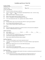
1
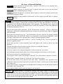
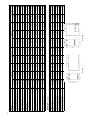
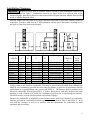
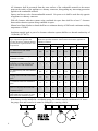
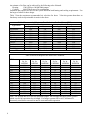
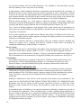
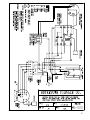
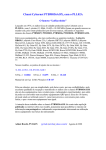
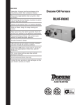
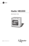
Oil Fired Furnace
Installation and Operation Instruction
Manual
Keep these instructions with the furnace at all times
for future reference
Boyertown Furnace Co.
PO Box 100
Boyertown, PA 19512
610-369-1450
www.boyertownfurnace.com
2/26/09
Be Aware of Hazard Definitions
Danger
Denotes presence of a hazard which, if ignored, will result in severe personal injury,
death or property damage
Warning
Denotes presence of a hazard which, if ignored could result in severe personal injury,
death or substantial property damage.
Caution
Denotes the presence of a hazard, which if ignored, could result in minor personal injury
or property damage
Notice
Intended to bring attention to information, but not related to personal injury or property
damage.
Danger
This equipment must be installed, adjusted and started only by a qualified service agency –
an individual or agency, licensed and experienced with all codes and ordinances, and who is
responsible for the installation and adjustment of the equipment. The installation must comply with
all local codes and ordinances and with the latest revision of the National Fire Protection Standard for
Oil Burning Equipment, NFPA 31.
Read all instructions before proceeding. Follow all instructions completely. Failure to follow these
instructions
Warning could result in equipment malfunction causing severe personal injury, death or substantial
property damage.
Do not alter this furnace in any way. The manufacturer will not be liable for any damage resulting
from changes made in the field to the furnace or its components or from improper installation. Failure
to comply could result in severe personal injury, death, or substantial property damage.
Your oil fired furnace is designed to burn No. 1 and No. 2 heating oil only. Never use gasoline or a
mixture of gasoline and oil.
Do not store gasoline or other flammable vapors and liquids in the vicinity of this or any other
appliance.
The area around the furnace should be kept free and clear of combustible materials.
Never burn garbage or refuse in your furnace.
Never try to ignite oil by tossing burning papers or other material into your furnace.
Do not attempt to start the burner when excess oil has accumulated or the furnace is full of vapors.
Do not use the furnace as a construction heater.
Do not operate furnace if the heat exchanger is damaged. Toxic flue products could enter air stream.
Do not jumper, attempt to bypass or override any of the safety limit controls.
Do not use this furnace if any part has been under water. Immediately call a qualified service
technician to inspect the furnace and replace any part of the furnace, control system or burner that has
been under water.
Do not operate furnace if temperature rise through the heat exchanger exceeds that which is listed on
the Ratings Label (Typically75ºF).
Do not operate furnace without return air properly sized or ducted.
NOTICE
Concealed Damage- If you discover damage to the burner, furnace or controls during
unpacking, notify the carrier at once and file the appropriate claim. When calling or writing about the
furnace please have the following information available: the furnace model number and serial number
which is located on the upper portion of the front of the unit. Record the model and serial number for
future reference in the space provided in this manual.
2
TABLE OF CONTENTS
PAGE NO.
FURNACE SPECIFICATIONS
4
INSTALLATION CLEARANCES
Standard Clearances
Reduced Clearances
5
DUCT WORK
Sizing
Blower Specifications
Filter Racks
Multiple Furnace Installation
7
VENTING
Chimney Venting
Chimney Relining
Chimney Connector
Power Venting
Vent Dampers
10
VENTILATION AND COMBUSTION AIR
12
BURNER INSTALLATION
13
WIRING
Power
Thermostat
14
OIL TANK AND PIPING
16
START UP
Start Up Equipment
Burner Adjustments
17
OPERATING AND MAINTENANCE
Cleaning the Furnace
Oil Burner
Blowers – Belt Drive
Blowers – Direct Drive
Vent System
Fuel Oil System
Filters
19
PARTS BREAKDOWN LISTS
21
TROUBLE SHOOTING GUIDE
24
WARRANTY
26
INSTALLATION AND SERVICE CHECKLIST
27
WARRANTY REGISTRATION
28
3
4
DIMENSIONS (inches)
Cabinet Height
Cabinet Width
Cabinet Depth
Centerline Flue to Floor
Centerline Flue to Side
Warm Air Supply Depth
Warm Air Supply Width
Return Air Supply Width
Return Air Supply Depth
A
B
C
D
E
G
Ho
Hr
J
40
20 1/4
47 1/2
31 1/4
10 1/8
17 1/2
18 1/4
18 1/4
14
SPECIFICATIONS
MODEL
B.T.U.H. Input
85,000
B.T.U.H. Output
70,000
.60 80ºA
Nozzle Beckett AFG @ 100 PSI
.50 60ºA
Nozzle Riello 40 Series @ 150 PSI
.60 70ºA
Nozzle Carlin EZ-1 @ 100 PSI
Flue Size (inches)
6
AFUE Seasonal Efficiency
85.9%
Filter Size (inches)
(2) 16 x 20
Blower Size
100-10T
Blower Motor
3/4Hp 4sp
CFM @ 0.2" WC
High
1903
Med High
1711
Med Low
1547
Low
1399
CFM @ 0.5" WC
High
1661
Med High
1485
Med Low
1355
Low
1227
Cooling Capacity (tons)
4
Shipping Weight
323
40
20 1/4
47 1/2
31 1/4
10 1/8
17 1/2
18 1/4
18 1/4
14
120,000
95,000
.85 80ºB
.65 60ºA
.85 70ºA
6
85.0%
(2) 16 x 20
100-10T
3/4Hp 4sp
1903
1711
1547
1399
1661
1485
1355
N/R
4
323
Low Boy
Low Boy
40
20 1/4
47 1/2
31 1/4
10 1/8
17 1/2
18 1/4
18 1/4
14
LB-750
105,000
85,000
.75 80ºB
.60 60ºA
.75 70ºA
6
85.4%
(2) 16 x 20
100-10T
3/4Hp 4sp
1903
1711
1547
1399
1661
1485
1355
1227
4
323
46
25 1/8
53 5/8
38 1/2
12 1/2
21 1/2
22 7/8
22 7/8
13 5/8
46
25 1/8
53 5/8
38 1/2
12 1/2
21 1/2
22 7/8
22 7/8
13 5/8
LB-1000
140,000
175,000
115,000
140,000
1.00 80ºB
1.25 80ºB
.85 80ºB
1.00 80ºB
1.00 60ºSS 1.25 60ºSS
6
6
85.0%
84.2%
(2) 16 x 20 (2) 16 x 20
100-10T
100-10T
3/4Hp 4sp 3/4Hp 4sp
2466
2466
2150
2150
1839
1839
1600
N/R
2072
2072
1859
1859
1610
N/R
N/R
N/R
5
5
362
362
53 5/8
22 1/4
33 1/8
49 1/8
11 1/8
19 3/4
20 1/2
15
23 5/8
High Boy
53 5/8
22 1/4
33 1/8
49 1/8
11 1/8
19 3/4
20 1/2
15
23 5/8
85,000
70,000
.60 80ºA
.50 60ºA
.60 70ºA
6
85.9%
16 x 25
100-10T
3/4Hp 4sp
1745
1550
1376
1250
1480
1343
1175
1043
3 1/2
298
HB-750
105,000
85,000
.75 80ºB
.60 60ºA
.75 70ºA
6
85.4%
16 x 25
100-10T
3/4Hp 4sp
1745
1550
1376
1250
1480
1343
1175
N/R
3 1/2
298
53 5/8
22 1/4
33 1/8
49 1/8
11 1/8
19 3/4
20 1/2
15
23 5/8
120,000
95,000
.85 80ºB
.65 60ºA
.85 70ºA
6
85.0%
16 x 25
100-10T
3/4Hp 4sp
1745
1550
1376
1250
1480
1343
N/R
N/R
3 1/2
298
High Boy
56 1/2
25 1/2
38
52 5/8
12 3/4
23 3/8
23 3/4
15
23 5/8
56 1/2
25 1/2
38
52 5/8
12 3/4
23 3/8
23 3/4
15
23 5/8
HB-1000
140,000
175,000
115,000
140,000
1.00 80ºB
1.25 80ºB
.85 80ºB
1.00 80ºB
1.00 60ºSS 1.25 60ºSS
6
6
85.0%
82.3%
16 x 25
16 x 25
100-10T
100-10T
3/4Hp 4sp 3/4Hp 4sp
2283
2283
2130
2130
1901
1901
1717
N/R
2007
2007
1832
1832
1644
N/R
1501
N/R
5
5
347
347
Installation Clearances
WARNING Furnaces in rooms shall be installed with the clearances from combustible materials not
less than indicated in Table 1. Combustible materials are those made of or surfaced with wood,
compressed paper, plant fibers, plastics, or other material that will ignite and burn, whether flame proofed
or not, or whether plastered or not.
Place the furnace near the center of the supply and return ducts and as close to the chimney connector
as possible. Provide a solid brick or 2” thick minimum concrete pad if the furnace mounting area is
not level or if the floor can become flooded.
MODEL
HB600
LB600
HB750
LB750
HB850
LB850
HB1000
LB1000
HB1250
LB1250
Sides
“A”
2”
2”
2”
2”
2”
2”
2”
2”
2”
2”
Table 1 Standard Installation Clearances
Top
Front
Rear
Flooring
“B”
“C”
“D”
2”
2”
2”
2”
2”
2”
2”
2”
2”
2”
Alcove-24”
Alcove-24”
Alcove-24”
Alcove-24”
Alcove-24”
Alcove-24”
Alcove-24”
Alcove-24”
Alcove-24”
Alcove-24”
2”
2”
2”
2”
2”
2”
2”
2”
2”
2”
Combustible
Noncombustible
Combustible
Noncombustible
Combustible
Noncombustible
Combustible
Noncombustible
Combustible
Noncombustible
Chimney
Connector
“E”
18”
18”
18”
18”
18”
18”
18”
18”
18”
18”
Plenum
Top &
Sides
2”
2”
2”
2”
2”
2”
2”
2”
2”
2”
Lowboy furnaces not listed for combustible floor may be placed on combustible floors although not
listed for such installation, provided the floor under the furnace is protected in accordance with the
requirements of accepted building code practice and NFPA 31. The furnaces shall be permitted to be
placed on combustible flooring protected by 4” hollow block placed with ends unsealed and joints
matching in such a fashion as to permit free circulation of air from side to side through the masonry.
The block must be covered with sheet metal not less than 24 gauge.
Furnaces are permitted to be installed in rooms, but not closets, with lesser clearances to combustible
material, provided the combustible material is protected as described in Table 2 and NFPA 31. In no
case shall the clearance be such as to interfere with the requirements for combustion air, draft
regulators and accessibility.
5
All clearances shall be measured from the outer surface of the combustible material to the nearest
point on the surface of the appliance or chimney connector, disregarding any intervening protection
applied to the combustible material.
Spacers and ties are to be of noncombustible material. No spacer or tie shall be used directly opposite
an appliance or chimney connector.
With all clearance reduction systems using ventilated air space there shall be at least 1” clearance
between the reduction systems using ventilated air space.
Mineral wool batts, blanket or board shall have a minimum density of 8lb/ft3 and a minimum melting
temperature of 15000F.
Insulation material used as part of a clearance reduction system shall have a thermal conductivity of
1.0(Btu/In)/ (Ft2/Hr/0F).
Type of protection applied to and
covering all surfaces within the distance
specified as the required clearance with
no protection
Table 2 Allowable Clearances with Specified Protection
Where the Specified Clearance with No Protection from the Appliance or
Chimney Connector
18”
Above Rear &
Sides
12”
Above Rear &
Sides
9”
6”
Above
Rear &
Sides
Above
Rear &
Sides
3½” thick masonry wall without
ventilated air space
N/A
12”
N/A
9”
N/A
6”
N/A
5”
½” insulation board over 1” glass fiber
or mineral wool batts
12”
9”
9”
6”
6”
5”
4”
3”
24 gauge sheet metal over 1” glass fiber
or mineral wool batts reinforced with
wire on rear face with ventilated air
space
9”
6”
6”
4”
5’
3”
3”
3”
3½” thick masonry wall with ventilated
air space
N/A
6”
N/A
6”
N/A
6”
N/A
6”
24 gauge sheet metal with ventilated air
space
9”
6”
6”
4”
5”
3”
3”
2”
½” insulation board with ventilated air
space
9”
6”
6”
4”
5”
3”
3”
3”
9”
6”
6”
4”
5”
3”
3”
3”
6”
6”
6”
4”
5”
3”
3”
3”
24 gauge sheet metal with ventilated air
space over 24 gauge sheet metal with
ventilated air space
1” glass fiber or mineral wool batts
sandwiched between 2 sheets 24 gauge
sheet metal with ventilated air space
If the furnace is to be installed in a residential garage, the furnace must be a minimum of 18” above
the garage floor and located so it cannot be damaged by a moving vehicle.
6
Duct Work
NOTICE
The duct system should follow the design standards of Air Conditioning Contractors of
America (ACCA) or ASHRAE. The duct system should be sized for the maximum CFM capabilities
of the furnace being installed.
All trunk lines, take-offs, registers and grill free areas must be figured when determining the air
handling capacity of a duct system. By utilizing the Tables 3 through 5, one can obtain the necessary
duct system size. Use a supplier's catalog for proper sizing of outlet and return air registers to insure
that the register will meet the CFM requirements of the run to which it is connected. Do not exceed
the recommended flow rate. The pressure drop for each should not exceed 0.05 inch water column.
The return air ducts should equal the warm air duct system in CFM capacities. Avoid locating a return
air duct in rooms that may contain undue odors. Use only a return air filter mounted to or integral to
the furnace. Do not add additonal filters unless the duct system is sized to allow for the additional
pressure drop. An open return in a basement does not meet the requirements of return air.
Instruct the homeowner not to block any returns.
Always check the size of existing ducts, particularly if you are adding air conditioning. The pressure
drop through the cooling evaporator coil reduces available air flow. If the ducts are too small the
system may not work satisfactorily or be noisy on either heat or cooling.
If the furnace is used in connection with summer air conditioning, the furnace should be installed
parallel with or on the upstream side of the evaporator coil to avoid condensation in the furnace heat
exchanger. The evaporator coil must be installed at least 6” above the heat exchanger for proper air
flow. Distances less than 6” will result in decreased air flow. In all cases refer to the manufacturers
data for static pressure losses to ensure the total system static pressure does not exceed 0.5” WC. If
the cooling unit is installed with a parallel flow arrangement, dampers or other means used to control
flow of air should be provided to prevent chilled air from entering the furnace. If such a damper is
manually operated, it must be equipped with a means to prevent operation of either unit, unless the
damper is in the full heat or cool position.
NOTE: When a return register is located in the same room as the furnace, the register must be at least
20 feet away from the furnace.
To obtain proper CFM on a belt drive unit installed with air conditioning, the motor and/or blower
pulley may need to be changed. On a direct drive unit the blower motor speed may need to be changed
depending upon the size of the air conditioning system installed and the static resistance of the duct
system. See blower specifications for air conditioning CFM's at a .5 static.
Determining Air Flow CFM
The temperature rise through the0 furnace should not exceed 0the rated temperature rise as listed
on the Rating Label (Typically75 F) and should be at least 55 F for comfort.
The sensible heat temperature change
for cooling would be approximately 300F. Actual temperature
0
change will be approximately 20 F due to the humidity in the air.
To calculate the sensible heat change or temperature rise the following formula applies
∆T = (Btuh – Output)/(1.1 x CFM)
To calculate the air flow when you know the temperature rise the following formula applies
CFM = (Btuh – Output)/ (1.1 x ∆T)
7
An estimate of air flow can be achieved by the following rules of thumb:
Heating:
1300 CFM per 100,000 Btuh output
Cooling:
400 CFM per ton of air conditioning
Determine the required air flow for the system based on both heating and cooling requirements. Use
the larger of either for duct design.
Table 3 lists the maximum recommended air velocities for ducts. Velocities greater than those as
listed may result in objectionable air noise in the ducts.
Table 3 Recommended Maximum Duct Velocities, Feet Per Minute (FPM)
Main Ducts*
Branch Ducts
Application
Supply
Return
Supply
Return
Apartments
900
700
600
600
Auditoriums
1200
1000
1000
800
Banks
2000
1500
1600
1200
Hotel Rooms
1500
1300
1200
1000
Libraries
2000
1500
1600
1200
Meeting Rooms
2000
1500
1600
1200
Offices
2000
1500
1600
1200
Residences
900
700
600
600
Restaurants
2000
1500
1600
1200
Retail Stores
2000
1500
1600
1200
*When sound control is critical use branch duct velocities
Table 4 Duct Area Required at Listed Flow Conditions
Area
Area
Area
Area
Area
Area
Sq. In.
Sq. In.
Sq. In.
Sq. In.
Sq. In.
Sq. In.
2000FPM
1600FPM
1200FPM
1000FPM
800FPM
600FPM
50
12
100
24
18
14
12
150
36
27
22
18
14
200
48
36
29
24
18
14
250
60
45
36
30
23
18
300
72
54
43
36
27
22
400
96
72
58
48
36
29
500
120
90
72
60
45
36
750
180
135
108
90
68
54
1000
240
180
144
120
90
72
1250
300
225
180
150
113
90
1500
360
270
216
180
135
108
1750
420
315
252
210
158
126
2000
480
360
288
240
180
144
Note: For Systems not over 100 feet equivalent length. Do not apply this table to duct systems
which exceed 100 equivalent feet in length. For longer systems refer to ACCA Manual D.
Incorrectly sized ducts can result in unsafe or uncomfortable operation.
CFM
8
Nominal Size
Area in.2
Table 5 Round Duct Equivalent Area
5
6
7
8
19.6
28.3
38.5
50.3
4
12.5
9
63.6
10
78.5
12
113.1
Table 7 Direct Drive Blower Specifications
Model
HP
Speeds
RPM
Volts
Full
Load
Amp.
Capacitor
370 volt
mfd
Rotation
Blower
Model
Blower
Speed
AC
LB 750
3/4
4
1075
115
9.2
15
CCW
100-10T
Hi
LB 1000
3/4
4
1075
115
9.2
15
CCW
100-10T
Hi
HB 750
3/4
4
1075
115
9.2
15
CCW
100-10T
Hi
HB 1000
3/4
4
1075
115
9.2
15
CCW
100-10T
Hi
Blower
Speed
Change
Med
Low
Med
Hi
Med
Hi
Med
Hi
Blower
Speed
Heat
Low
Med
Low
Low
Med
Low
Table 8 Direct Drive Blower Performance
0.2 In. W.C. Static Pressure
0.5 In. W.C. Static Pressure
High
Med.
High
Med. Low
Low
High
Med.
High
Med. Low
Low
LB-600
1903
1711
1547
1399
1661
1485
1355
1227
LB-750
1903
1711
1547
1399
1661
1485
1355
1227
LB-850
1903
1711
1547
1399
1661
1485
1355
N/R
LB-1000
2466
2150
1839
1600
2072
1859
1610
N/R
LB-1250
2466
2150
1839
N/R
2072
1859
N/R
N/R
HB-600
1745
1550
1376
1250
1480
1343
1175
1043
HB-750
1745
1550
1376
1250
1480
1343
1175
N/R
HB-850
1745
1550
1376
1250
1480
1343
N/R
N/R
HB-1000
2283
2130
1901
1717
2007
1832
1644
1501
HB-1250
2283
2130
1901
N/R
2007
1832
N/R
N/R
MULTIPLE FURNACES IN COMMON DUCT WORK
Multiple furnaces connected to common duct work, either supply, return, or both supply and return
must be wired so that all furnace blower motors are energized at the same time.
WARNING Failure to turn all blowers on at the same time can cause a reversal of air flow in those
units where the blower motor is not operating. This reversal of air flow can cause premature blower,
blower motor, wiring and or heat exchanger failure.
Please consult the factory for specific wiring instructions for your application.
9
VENTING
Failure to follow all instructions can result in flue gas spillage and carbon monoxide
WARNING
emissions, causing severe personal injury or death. All chimneys must meet the requirements of
NFPA 211 and NFPA 31
Chimney
The furnace must be connected to an adequate chimney or an approved venting system in accordance
with these instructions. An adequate chimney or venting system is one that is sealed and lined with the
capability of producing a -.04" W.C. flue draft and having the capacity to handle the amount of flue
gas that is introduced. A chimney with an internal construction of corrosion resistant tile, stainless
steel, or some other material that will withstand flue gas temperatures up to 10000F is required.
Masonry and metal chimneys shall be constructed in accordance with applicable building code
requirements. Masonry chimneys shall be lined with an approved clay tile liner or a listed chimney
lining system installed in accordance with manufacturers’ instructions and also meeting the
requirements of NFPA-211 Standard for Chimneys, Fireplaces, Vents, and Solid Fuel-Burning
Appliances. Metal chimneys also shall meet the requirements of NFPA-211. Factory built chimneys
shall be listed and shall be installed in accordance with their listing and NFPA-211.
Prior to installation of the furnace, the chimney or venting system shall be examined by the installer
and determined to be in good condition. All joints of the chimney must be tightly sealed. The inside of
the chimney should be free of all obstruction, such as loose brick, broken pieces of tile, or corroded
metal. If chimney flues are divided or there are multiple flues within one chimney, make sure there are
no openings in the partition separating the divided or individual flues. When a new appliance is
connected to an existing chimney, that chimney shall be brought up to current requirements.
Chimneys which are relined shall be done so with an approved liner that will resist corrosion,
softening, or cracking from the flue gasses.
All chimney clean-out doors and flue connections must fit tightly so they will seal to avoid air
leakage.
The inside area of the chimney liner should equal, at a minimum, the area of the vent pipe exiting the
furnace. If more than one appliance is installed, the area of both appliances shall be used in
determining the required inside area of the chimney.
The flue gas exit of a chimney shall be at least 3 feet above the highest point where it passes through
the roof of a building and at least 2 feet higher than any portion of a building within 10 feet of such
chimney.
The chimney height will also be determined by the height of the surrounding trees, buildings and
terrain. When chimney downdraft conditions cause faulty operation that creates a hazard, corrective
steps must be taken.
When altering the surrounding obstructions is not possible, a chimney cap can be constructed on the
top of the chimney to avoid downdrafts. The chimney cap should be pyramid shaped on the top with a
perfectly flat surface immediately above the chimney outlet. The hood should be attached by four (4)
iron supports. The four iron supports should be equal in height to the width of the chimney opening.
Four plates, flaring down, can be added to help insure that the wind will pass straight over the
chimney outlet.
Chimney Relining
A tile lined masonry chimney serving an oil fired furnace should comply with applicable building
codes such as NFPA-211. An additional listed lining may be required to reduce transient low draft
10
during startup and acid water condensation during cyclic operation. This is particularly true for high
mass masonry chimneys serving oil fired furnaces of higher efficiency. For masonry chimneys, local
experience can indicate how well construction has withstood the lower temperatures produced by
higher efficiency furnaces.
Evidence of potential or existing chimney damage should be determined by visual inspection of the
chimney and liner. Exterior indicators such as missing or loose mortar/bricks, white deposits on the
brick or water stains on the interior building walls should be investigated further. The operational flue
temperatures for furnaces range from 350ºF to 550ºF at the outlet of the furnace. These temperatures
are further reduced before reaching the chimney due to heat loss through the vent connector and
dilution from the draft regulator. The resulting flue gas temperatures may become low enough to
form condensation on the chimney liner walls.
To prevent condensation, it is necessary that the internal chimney wall temperature always be kept
above the dew point of the flue gasses. If the chimney is a masonry type, it may have to be lined with
a flue liner, if the temperature loss is too great for the furnace. A liner will act as an insulator and
reduce the flue gas temperature loss. Insulation may be added around the liner for further temperature
stability. Refer to NFPA-31 for recommended liner sizing tables as developed by the Oil Heat Vent
Analysis Program.
Chimney Connector
The chimney connector pipe between the furnace and chimney shall be of equal diameter as the flue
outlet of the furnace. Refer to furnace specifications in this manual for proper size flue pipe for your
model furnace. Any reduction in size required for the chimney must be made at the chimney
connector. The vent connector pipe must be made of 24 gauge (or thicker) corrosion-resistant steel.
The vent connector pipe should be as short as possible and installed so that it has a continuous rise
from the furnace to the chimney. Long horizontal vent runs can result in the possibility of
condensation in the flue pipe or the chimney. All horizontal runs of vent connector pipe should be
pitched upward a minimum of 1/4 inch per foot of run. The horizontal length of the vent pipe
connector shall not exceed 10 feet. The chimney connector shall be installed so as to minimize the
number of elbows and to avoid sharp turns or other construction features that would create excessive
resistance to the flow of flue gasses. Tees may be used in a straight section in conjunction with a
barometric draft regulator; however, they must not be used for a 90° turn. No device that will obstruct
the free flow of flue gasses shall be installed in the chimney connector. This does not exclude the use
of devices specifically designed for the use in chimney connectors such as automatic dampers. The
vent pipe should be joined with metal screws and supported by straps. A thimble should be used to
connect the vent connector pipe to the chimney so the pipe may be readily removed in case of
inspection or replacement.
No chimney connector shall pass through any floor or ceiling. The vent connector pipe must not pass
through a combustible wall or partition unless they are guarded at the point of passage by a ventilated
metal thimble not less than 12 inches larger in diameter than the connector, on metal or fireclay
thimbles adequate protection is provided at the passageway. An acceptable passageway could be
either an approved, ventilated metal thimble which is at least 12 inches larger in diameter than the
vent connector pipe, or brick work which is at least 8 inches thick constructed into the wall and
surrounding the vent connector
Clearances from combustible materials or materials shall be in accordance with the clearances given
in Tables 1 or 2. The vent connector pipe should extend only to (and not beyond) the inside wall of
the chimney. A thimble should be used to connect the vent connector pipe to the chimney so that the
vent connector pipe may be readily removed in case of inspection or replacement.
Connection to the chimney must be made above the bottom of the chimney to avoid blockage. Vent
piping should extend just into the chimney far enough to expel flue gasses. Inserting the vent piping
11
too far into the chimney will cause undue obstruction. Use a thimble or a slip joint where vent pipe
enters the chimney to allow easy removal for cleaning.
A draft regulator, which is shipped in the blower compartment, must be installed in the vent piping. It
should be located at least 24 inches from the furnace if possible in either a horizontal or vertical
section of the vent pipe. The draft regulator must be installed in the same room as the furnace and in
such a manner that there is no difference in pressure between the air in the vicinity to the regulator and
the combustion air supply. Ensure that the barometric damper is accessible for adjustment.
With the burner operating, use a draft gauge to adjust the regulator to the proper setting (see
instructions enclosed with draft gauge to adjust the regulator to the proper setting). When the burner
air supply and draft are properly adjusted, the over-fire draft should be a negative .02" W.C.
Two or more oil burning appliances each equipped with a safety control may be permitted to be
connected to one common chimney if sufficient draft is available for the safe simultaneous removal of
all products of combustion.
If two or more openings are provided into one chimney, they shall be at different levels on the same
story of the building, with the smaller appliance entering at the highest possible level consistent with
clearances to combustible materials.
Two or more connectors shall not be joined together unless the common connector, manifold and
chimney are properly sized. Adequate draft must be available to safely remove all products of
combustion simultaneously without leakage, or back flow.
Power Venting
The furnace may be power vented through a side wall by using a listed power side wall Venter. The
vent device must be able to produce a draft of -.02”W.C. over the fire and be equipped with a post
purge timer set to a minimum time of 5 minutes. The power vent must be installed in accordance with
the recommendations of the manufacturer, all applicable building code requirements, and NFPA-31.
Vent Dampers
Do not install a thermal type vent damper on the furnace. Failure to comply could result in severe
personal injury, death or substantial property damage. If a vent damper is required, use only a
motorized damper, wired and installed following the vent damper manufacturers instructions.
Ventilation and Combustion Air
Appliances shall be installed in a location where the facilities for ventilation permit the satisfactory
combustion of oil, proper venting and the maintenance of ambient temperature at safe limits under
normal conditions of use. The burner requires a generous amount of clean combustion air to operate
safely. The furnace room must be well ventilated to allow sufficient make-up air to support
combustion.
Inadequate combustion air may result in erratic operation of the burner, noisy combustion or fuel
odors in the air. NEVER BLOCK THE FURNACE FROM THE SUPPLY OF COMBUSTION AIR.
Remember, your need for outside air will be greatly increased if you have a vented dryer in the
basement or other venting fans in the home. Do not install an exhaust fan in the same room as the
furnace.
In unconfined spaces in buildings of conventional construction, infiltration is adequate to provide air
for ventilation and combustion. If the unconfined space is within a building having insufficient air
because of tight construction, the air required for combustion and ventilation shall be obtained from
outdoors or from spaces freely communicating with the outdoors. In this situation, permanent
openings having a total free opening area of not less than 1 square inch per 5000Btu/Hr of total input
of all appliances must be provided.
12
If the furnace is located in a confined space (A space whose volume is less than 50 cubic feet per
1000Btu/Hr of the combined input ratings of all appliances installed in that space) the confined space
shall have two permanent openings, one 6 inches from the top of the space and one 6 inches from the
bottom of the space. Each opening shall have a free area opening of not less than 1 square inch per
1000Btu/Hr of total input rating of all appliances in the enclosure freely communicating with interior
areas having adequate infiltration with the outside.
If adequate infiltration air is not available the confined space shall be fitted with two openings, one 6
inches from the top of the enclosure and one 6 inches from the bottom of the enclosure. Each opening
shall have a free area of at least 1 square inch per 2000Btu/Hr of the total input of the appliances in
the enclosure.
In calculating free area, consideration must be given to the blocking effect of louvers, screens or grills
protesting the opening. Screens used shall not be less than ¼” mesh and shall be readily accessible for
cleaning.
Burner Installation
NOTICE
Remove the oil burner from its shipping carton and inspect thoroughly. Verify that the
correct burner combination and nozzle is installed in the burner as shipped.
Read the oil burner manual included in the shipping carton and follow the instructions for preparing
and installing the burner. Refer to Table 9, Table 10, or Table 11 for the burner specifications for
your unit.
On units which can be multi fired, a nozzle change may be required. Follow the oil burner manuals
instructions for the proper installation of the nozzle.
Verify that the electrode settings match the manufacturers recommended settings.
Inspect the combustion chamber. Verify that it is in the correct position in the heat exchanger and is
in good condition.
The oil burner is to be bolted to the pouch plate using the burner mounting flange gasket and the nuts
supplied. Make sure that the burner passes through the burner opening in the combustion chamber and
does not protrude into the combustion chamber. Refer to the wiring section of this manual for the
correct wiring connections to the furnace and to the oil burner manual for fuel piping.
Table 9 Beckett Burner Specifications
Furnace Model
Burner
Delavan
Pump
Air
Air
Head Tube
Insertion
Model
Nozzle
Press. Band1 Shutter1
Length
LB/HB600
F-32
AFG
100
0
4
6-1/2”
5-1/2”
0.60X80ºA
F-32
LB/HB750
100
0
6
6-1/2”
5-1/2”
AFG
0.75X80ºB
2
º
LB/HB850
F-3
AFG
0.85X80 B
100
0
9
6-1/2”
5-1/2”
F-62
LB/HB1000
100
0
5
9”
7-3/4”
AFG
1.00X80ºB
2
º
LB/HB1250
F-6
AFG
100
0
8.5
9”
7-3/4”
1.25X80 B
Notes: 1. Approximate air settings, see start up procedures for final adjustments.
2. With ceramic amulet and Stainless Air Tube. 3. Low Firing Rate Baffle installed.
Static
Plate
3-3/8
3-3/8
3-3/8
3-3/8
3-3/8
13
Table 10 Riello Burner Specifications
Furnace Model
Burner Delavan
Pump
Air
Turbulator
Model Nozzle
Press.
Setting1
Setting
LB/HB600
0.50X60ºA
150
2.75
3.0
40F3
º
LB/HB750
0.60X60 A
40F3
150
4.0
3.0
º
LB/HB850
0.65X60 A
150
5.25
3.0
40F3
LB/HB1000
0.85X80ºB
40F5
150
2.75
4.0
º
LB/HB1250
1.00X80 B
150
3.6
4.0
40F5
Notes: 1. Approximate air settings see start up procedures for final adjustments
2. Burner Amulet Required
Tube
Length
8”
8”
8”
8-7/8”
8-7/8”
Insertion
5-1/4” 2
5-1/4” 2
5-1/4” 2
7-1/2” 2
7-1/2” 2
Table 11 Carlin Burner Specifications
Burner Nozzle
Pump
Air
Air Bar1
1
Model
Press.
Band
º 2
LB/HB600
0.60X70
A
EZ-1
100
0.60
0.60-0.65
LB/HB750
0.75X70ºA2
EZ-1
100
0.75
0.75
º 2
LB/HB850
0.85X70 A
100
0.85
0.85-1.00
EZ-1
LB/HB1000
1.00X60ºSS3
EZ-1
100
1.00
0.85-1.00
º
3
LB/HB1250
1.25X60 SS
EZ-1
100
1.25
1.10-1.25
Notes: 1. Approximate air settings - see start up section for final adjustments
2. Delavan nozzle 3. Hago nozzle
Furnace Model
Tube
Length
7”
7”
7”
9”
9”
Insertion
5-1/2”
5-1/2”
5-1/2”
8”
8”
Wiring
WARNING
Electric shock hazard can cause severe personal injury or death if power source,
including service switch for the furnace, is not disconnected before installing or servicing the unit.
All wiring must conform to the National Electrical Code NFPA 70, latest edition and any additional
state or local codes.
All wiring must be N.E.C. Class 1. If original wiring as supplied with the furnace must be replaced,
replace with type 105ºC wire or equivalent only.
Power
Supply wire for the furnace must be sized for the load requirement as listed on the furnace rating plate.
Connect 120 VAC 60HZ single phase separate electrical line from the main house panel to the power
leads in the junction box attached to the furnace as indicated in the electrical wiring diagrams.
Provide a fused disconnect in the power line following all code requirements. Connect the burner to
the factory wired burner harness as shown in the electrical diagrams.
Provide electrical ground at the furnace as required by codes.
Thermostat
Locate the room thermostat on an interior wall in the natural circulating path of room air. Do not
locate the thermostat so it is exposed to cold air infiltration, drafts from windows or doors, air currents
from supply or return air registers, behind obstructions, in a closet or in a corner.
Ensure the thermostat won’t be exposed to heat from nearby fireplace, radio, television, lamp or rays
from the sun. Do not mount thermostat on a wall over a supply or return duct, chimney or vent.
Wire the thermostat to furnace and set the thermostat anticipator as shown on the oil burner primary
control. Failure to properly adjust the heat anticipator could result in short cycling of the furnace or
overheating the home.
14
15
Oil Tank and Piping
WARNING Installation of oil tanks must meet all local codes and ordinances. Refer to NFPA-31 for
complete guidelines on oil tank installations internal to the building, outside above and below ground
tanks.
Oil tanks located inside the building shall not be in excess of 275 gallons individual capacity and shall
not be located within 5 feet horizontally from any source of heat, either internal or external to the
appliance being served or in a manner that the temperature of the oil in the tanks exceeds 25ºF above
room temperature.
Connect burner to oil supply using the correct size heavy wall copper tubing, wrought iron, steel or
brass fittings in accordance with the literature attached to the pump. All lines must have shut off
valves, a good pipe joint compound approved for use with oil on all pipe threads, no kinks, no sharp
bends, and be properly tested for leaks. Use flare fittings only when assembling oil lines. Avoid use
of fittings in inaccessible locations. Avoid running tubing against any type of heating unit and across
ceiling or floor joists. Piping shall be supported and protected from physical damage and where
necessary, protected against corrosion as per code. Piping systems shall be maintained liquid tight. A
piping system that has leaks constitutes a hazard which must be repaired in an approved manner. All
oil feed lines to burners must be air tight. The slightest air leak, caused by loose fittings, bad gaskets
or any other reason, can cause a foaming oil stream which will cause any of the following conditions:
a) Intermittent firing, causing safety shutdown.
b) Poor starts.
c) Smokey starts.
d) Continual sooting of furnace and burner parts including the cad cell.
e) Reduced firing rate, inefficient operation and erratic fire pattern.
f) A dangerous combustion condition, allowing the combustion chamber to fill with a lean
mixture (too much air in the oil stream) which could cause a delay in ignition of the fuel
mixture until the danger point has been reached.
This fuel unit when connected with a single pipe system is satisfactory only where the oil supply is on
the same level or above the burner, permitting gravity flow of oil. When it is necessary to lift oil to the
burner, a return line must be connected between the fuel unit and the tank. This requires the insertion
of the "bypass" plug in the oil pump. The bypass plug and pump instructions are attached to the pump.
Installation of a check valve in the suction line of a two pipe system is advisable under all
circumstances. Be sure the check valve fittings are air tight. If lift exceeds 10 ft. a two-stage pump
must be installed with a two pipe system.
If any part of the fuel oil tank is above the burner, an anti-siphon device must be used to prevent the
flow of oil in case of an oil line breakage.
Suction vacuum must be held to acceptable limits. THE VACUUM TEST IS WORTH THE TIME
REQUIRED TO MAKE IT. This problem becomes proportionately larger with underground tanks.
Connect vacuum gauge to oil pump. Suction vacuum must not exceed 10 inches of mercury for single
stage pumps and 15 inches for two stage pumps. It is preferable to stay below these limitations. When
the suction line is tight and properly installed the pump will hold its vacuum for a minimum of 60
minutes after shutdown.
Use an oil filter with the proper capacity to filter for all installations. Install the filter inside the
building between the tank shutoff valve and the burner. The filter cartridge should be replaced at least
once a year. The filter body should be thoroughly cleaned before installing a new cartridge.
16
Start-Up
WARNING Use number No. 2 fuel oil only.
Do not attempt to start the burner if excess oil has accumulated.
Do not use gasoline, crankcase draining or any oil containing gasoline.
This equipment must be adjusted and started only by a qualified service agency – an individual or
agency, licensed and experienced with all codes and ordinances, and who is responsible for the
installation and adjustment of the equipment.
1. Check that all safety devices are in place.
2. Check that thermostats are correctly connected and set.
3. Check that the inside of the furnace is free of any fuel residue or foreign materials and that the
refractory chamber has not been damaged.
4. Check oil burner nozzle to ensure that the right size and type is installed and tight in the adapter.
See preliminary settings for proper nozzle size and type.
5. Check electrode settings, as they may have been jarred out of position during transportation. See
oil burner instructions for nozzle and electrode setting
6. Check air setting to ensure that it matches the preliminary air settings as found in Table 9, Table
10, or Table 11.
7. Check that the Burner mounting bolts are tight.
8. Lubricate burner motor and circulator motor if required.
9. Open all oil lines valves.
10. Set room thermostat to call for heat.
11. Turn service switch on. Burner should start. On one pipe fuel system only you may have to bleed
the oil system. To bleed attach a clear plastic tube to the oil pump bleed port and allow oil to run
until all the air is out of the oil suction line feeding the oil burner. If air is still evident in the bleed
line you must check the oil lines, all fittings, filters and any other connections for tightness. See
burner and fuel pump manufacturers recommendations for proper bleeding of the fuel system.
CAUTION: DO NOT RUN THE PUMP DRY FOR MORE THAN FIVE MINUTES, AS
IRREPAIRABLE DAMAGE MAY RESULT.
12. Turn “OFF” burner and install pressure gauge and vacuum gauge into the proper ports on the
pump. See the burner manufacturer’s manual for location of ports.
13. Start burner again and check oil pressure. Adjust if necessary. See oil burner manufacturers’
instructions for pump adjustment.
Start-up Equipment
THE FOLLOWING PROPER COMBUSTION INSTRUMENTS ARE REQUIRED TO
DETERMINE PROPER AIR ADJUSTMENTS AND DRAFT WHEN SETTING UP OR
SERVICING THE OIL BURNER. DO NOT ATTEMPT TO START UP OR SERVICE THE
FURNACE WITHOUT THE PROPER COMBUSTION INSTRUMENTS.
1.
2.
3.
4.
5.
6.
Carbon-dioxide (C02) or Oxygen (02) Analyzer
Draft gauge. Scale should read from +.10" W.C. to -.25" W.C.
Oil Pressure Gauge 0-200 PSI
Stack Thermometer
Plenum Thermometer
Smoke Test Gun
17
7. Vacuum Gauge 0-30 in. of Hg
8. Volt meter
9. Amp meter
Burner Adjustments
Allow the burner to operate for at least 10 minutes before making the following adjustments. The
factory burner settings may not be suitable for specific job conditions.
Do not attempt to make any adjustments or start the furnace without the proper equipment.
1. A 5/16” diameter hole will be required in the flue pipe between the furnace and the barometric
damper as close to the furnace as possible.
2. Set the draft regulator (barometric damper) using a draft gauge to obtain a negative draft over-fire
of -.01 to -.02 in. W.C.
3. Pump pressure – Install a pump pressure gauge in the oil pump following the oil burner
manufacturers’ recommendations. Adjust to obtain required pressure as necessary.
4. Combustion Set-up – The air settings shown in Table 8 thru Table 10 are approximate. The
burner must be adjusted during actual field installed conditions. Failure to do so will result in
poor performance and nuisance service calls. After proper draft and oil pressure have been
established:
a. Begin to close the air band to create a slight trace of smoke as noted on the Bacharach or
equivalent smoke tester scale.
b. Take a flue gas sample and note the CO2 reading. It will be about 12% to 13.5%
c. Open the air band to reduce the CO2 approximately 2%. The desired CO2 setting for all
units should be 10% to 11%
d. Check for “0” smoke. Head settings and/or air band may be altered to obtain the above
results. Lock the air band and head setting screws in place.
5.
6.
7.
8.
18
The above procedure will give a built in margin to ensure clean operation throughout the heating
season. Should draft conditions vary, lint accumulate in the fan, heavier oil delivered, or other
adverse conditions be encountered you will have a reasonable margin of built in protection before
smoke generation begins.
Flue Gas Temperature - The flue gas temperature will vary to some degree depending on BTU
inputs, duct design and the air flow across the heat exchanger. The suggested minimum NET
stack temperature is 350ºF, and the maximum stack temperature is 550ºF. The lower the stack
temperature, the higher the efficiency; however, stack temperatures under 350ºF may cause
condensation which in turn may cause metal corrosion.
Temperature Rise - Supply air temperature minus return air temperature. The temperature rise
across the furnace (operating at steady state conditions) should be approximately 75ºF. A higher
temperature rise would slightly lower the efficiency. The supply air temperature should be
measured in the supply air trunk-line approximately 12 inches down stream of the plenum.
Do not exceed the maximum temperature rise as listed on the furnace nameplate.
Check operation of the cad cell relay by removing cad cell wire from external terminal of primary
safety control to ensure that it goes off on safety.
Check blower motor amperage under both heating and air conditioning loads and ensure that the
amperage is less than the full load nameplate amperage of the blower motor.
Operating and Maintenance Instructions
WARNING
The furnace must be installed, adjusted and maintained only by a qualified service
agency annually. Have your unit inspected, cleaned and adjusted at least once a year to assure proper
operation. Do not tamper with the unit or controls. Incorrect operation of the unit could result in
severe personal injury and property damage.
Never attempt to use gasoline in the furnace.
Never store gasoline or other combustible materials near the burner or appliance. The area around the
furnace should be kept clear of all combustible materials.
Never attempt to burn garbage or refuse in the furnace.
Never attempt to light the furnace by throwing burning material into the furnace.
Never attempt to use crankcase or waste oil or materials other than the approved fuel oils in this
furnace.
Never restrict the air inlet openings to the burner.
Do not attempt to start the furnace when excess oil has accumulated in the chamber or the furnace is
full of vapors.
Cleaning
WARNING
Cleaning the heat exchanger must be done yearly by a qualified service technician.
It is important to inspect and clean the heat exchanger once annually or as necessary to remove any
build up of soot. A layer of soot on the inside surface of the heat exchanger will result in reduced
efficiency.
1. Turn off all power to the furnace.
2. Remove clean out caps and the flue pipe.
3. Remove the burner and burner mounting plate. Extreme care must be used when removing
the burner mounting plate as the ceramic fiber combustion chamber is directly attached to
the burner mounting plate.
4. With access to the inside of the heat exchanger through the cleanout openings, burner
opening, and vent opening use a soft flue brush to remove any soot build up.
5. Vacuum any loose debris. Do not use a vacuum on the combustion chamber.
6. Inspect heat exchanger and combustion chamber.
7. Replace the burner mounting plate with chamber, burner, vent pipe and burner. Replace
any of the gaskets which would not be able to provide an adequate seal.
8. Clean and readjust the oil burner as required.
Oil Burner
NOTICE
Refer to the oil burner instruction manual provided with the burner for proper
maintenance and service.
Burner Components: If replacement of burner parts is necessary, always use parts recommended by
the manufacturer. Specify part number and description when ordering.
19
Electrode settings are important for reliable ignition of the oil. Check to be sure the settings are in accordance with the instructions provided in the burner manual.
Nozzles: ANY NOZZLE REPLACEMENT SHOULD BE OF THE EXACT TYPE AS THE
ORIGINAL SUPPLIED BY THE MANUFACTURER. Use extreme care in handling nozzles to avoid
scratches or dirt that could cause leaks or affect the oil spray pattern.
Perform the combustion checks as per the burner manual and the furnace manual.
Blowers - Direct Drive
Clean inspect blower wheel annually. Lubricate blower motor as per the motor manufacturer’s
recommendations.
Vent System
Clean and inspect the flue pipe draft regulator and chimney annually as outlined in this manual.
Fuel Oil System
Check oil tank and piping for leaks annually, replacing the oil filter to avoid contamination of the fuel
unit and nozzle.
Filters
Air filters should be inspected and replaced if required monthly. The filters supplied with the furnace
are disposable and need to be replaced with the exact type and size as supplied. Dirty or clogged air
filters will impair the furnace performance and may cause the furnace to shut down or overheat.
Do not add additional filters unless the duct system is sized to allow for the additional pressure drop.
20
Item
No.
1
2
3
3
3
4
5
6
7
8
9
10
11
12
13
14
15
16
17
18
19
20
21
22
23
24
25
26
27
28
29
30
31
Qty
1
1
1
1
1
1
2
2
1
1
2
1
1
1
1
1
1
1
4
1
1
2
1
1
1
1
1
1
1
1
2
1
1
Description
FRONT PANEL
FRONT DOOR
BECKETT BURNER
RIELLO BURNER
CARLIN BURNER
POUCHPLATE ASSEMBLY
SIDE POUCHPLATE GASKETS
UPPER/LOWER POUCHPLATE GASKETS
COMBUSTION CHAMBER
INNER FRONT PANEL
CAPS
FAN & LIMIT CONTROL
HEAT EXCHANGER
REAR PANEL
REAR BAFFLE
RIGHT SIDE PANEL
BLOWER MOTOR
BLOWER MOTOR LEG BAND
BLOWER MOTOR LEGS
BLOWER WHEEL
BLOWER
BLOWER LEGS
ELECTRON TERMINAL BOARD
CAPACITOR
BLOWER PARTITION
BASE PAN
TOP PANEL
JACKET COLLAR
FAN CENTER RELAY
LEFT SIDE PANEL
JACKET SIDE BAFFLE
BLOWER ASSEMBLY COMPLETE
POUCH PLATE ASSEMBLY W/CHAMBER
HB750
Part No.
15353
15354
540605B
540850
540800
15739W
15601
15600
15610
15355
15738
552324
15810
15356
15360
15350
712491
710026
710025
710356
710401
15150
310285
712430
15357
15358
15352
15410
552250
15351
15359
15105
15739C
HB1000
Part No.
15453
15454
540607B
540855
540810
15766W
15603
15602
15611
15455
15738
552323
15830
15456
15360
15450
712491
710026
710025
710356
710401
15150
310285
712430
15457
15458
15452
15461
552250
15451
15459
15105
15766C
21
Item
No.
1
2
2
2
3
4
5
6
7
8
9
10
11
12
13
14
15
16
17
18
19
20
21
22
23
24
25
26
27
28
29
30
31
32
33
22
Qty
1
1
1
1
1
2
2
1
1
1
2
1
1
1
1
1
1
1
1
1
1
1
4
1
1
1
1
4
2
1
1
1
1
1
1
Description
FRONT PANEL
BECKETT BURNER
RIELLO BURNER
CARLIN BURNER
POUCHPLATE ASSEMBLY
SIDE POUCHPLATE GASKETS
UPPER/LOWER POUCHPLATE GASKETS
COMBUSTION CHAMBER
TOP PANEL
JACKET COLLAR
CAPS
FAN & LIMIT CONTROL
INNER FRONT PANEL
HEAT EXCHANGER
TOP CHANNEL
BLOWER PARTITION
BLOWER PARTITION BRACKET
FILTER SUPPORT ASSEMBLY
REAR PANEL
REAR DOOR
BLOWER MOTOR
BLOWER MOTOR LEG BAND
BLOWER MOTOR LEGS
BLOWER
CAPACITOR
ELECTRON TERMINAL BOARD
BLOWER WHEEL
RUBBER GROMMETS
BLOWER LEGS
RIGHT SIDE PANEL
BASE PAN
FAN CENTER RELAY
LEFT SIDE PANEL
BLOWER ASSEMBLY COMPLETE
POUCH PLATE ASSEMBLY W/CHAMBER
LB750 FF
Part No.
15303
540605B
540850
540800
15739W
15601
15600
15610
15302
15410
15738
552323
15306
15805
15304
15307
15411
15412
15308
15305
712491
710026
710025
710401
712430
310285
710356
712100
740767
15300
15309
552250
15301
15100
15739C
LB1000 FF
Part No.
15403
540607B
540855
540810
15766W
15603
15602
15611
15402
15410
15738
552323
15406
15825
15404
15407
15411
15412
15408
15405
712491
710026
710025
710401
712430
310285
710356
712100
740767
15400
15409
552250
15401
15105
15766C
Item
No.
1
2
2
2
3
4
5
6
7
8
9
10
11
12
13
14
15
16
17
18
19
20
21
22
23
24
25
26
27
28
29
30
31
32
33
34
Qty
1
1
1
1
1
2
2
1
1
2
1
1
1
1
1
1
1
1
1
1
1
1
1
4
1
1
1
1
4
2
1
1
1
1
1
1
Description
FRONT PANEL
BECKETT BURNER
RIELLO BURNER
CARLIN BURNER
POUCHPLATE ASSEMBLY
SIDE POUCHPLATE GASKETS
UPPER/LOWER POUCHPLATE GASKETS
COMBUSTION CHAMBER
TOP PANEL
CAPS
FAN & LIMIT CONTROL
INNER FRONT PANEL
HEAT EXCHANGER
TOP CHANNEL
BLOWER PARTITION
BLOWER PARTITION BRACKET
EXTENSION PIPE W/FLANGE
FILTER SUPPORT ASSEMBLY
JACKET COLLAR
REAR PANEL
REAR DOOR
BLOWER MOTOR
BLOWER MOTOR LEG BAND
BLOWER MOTOR LEGS
BLOWER
CAPACITOR
ELECTRON TERMINAL BOARD
BLOWER WHEEL
RUBBER GROMMETS
BLOWER LEGS
RIGHT SIDE PANEL
BASE PAN
FAN CENTER RELAY
LEFT SIDE PANEL
BLOWER ASSEMBLY COMPLETE
POUCH PLATE ASSEMBLY W/CHAMBER
LB750 RF
Part No.
15303
540605B
540850
540800
15739W
15601
15600
15610
15302
15738
552323
15306
15807
15304
15307
15411
15732W
15412
15410
15308
15305
712491
710026
710025
710401
712430
310285
710356
712100
740767
15300
15309
552250
15301
15100
15739C
LB1000 RF
Part No.
15403
540607B
540855
540810
15766W
15603
15602
15611
15402
15738
552323
15406
15827
15404
15407
15411
15760W
15412
15410
15408
15405
712491
710026
710025
710401
712430
310285
710356
712100
740767
15400
15409
552250
15401
15105
15766C
23
Troubleshooting Guide
WARNING This equipment must be serviced, adjusted and started only by a qualified service
agency – an individual or agency, licensed and experienced with all codes and ordinances, and is
responsible for the installation and adjustment of the equipment.
Burner Goes Off on Safety
No
Oil T ank Full
Fill T ank
Yes
Bleed Oil Lines
Oil flows Freely
No
Fuel Supply
Valves Open
Yes
Air in Oil Lines
No
Open All
Supply Valves
No
Replace Oil
Filter
Yes
Yes
Check All Fitting
Connections
Oil Filter Clean
Yes
No
Pump Strainer
Clean
Pump Pressure
Per Set-up Label
No
Adjust Pressure
Per Set-up Label
No
No
Clean or
Replace Strainer
Refer to Burner
Manual
Yes
Spark Established
No
Yes
Ignition Electrode Yes
Shorted or
Cracked Porcelain
Replace
Electrodes
No
Refer to Burner
Manual
Nozzle Clean and
Matches
Preliminary Settings
No
Replace
Nozzle
Yes
Air Settings Match
Preliminary
Settings
Yes
Refer to Burner
Manual for Control
T rouble Shooting
24
No
Adjust Air
Settings
Burner Will Not Start
T hermostat Set
Above Room
T emperature
No
Adjust
T hermostat
Yes
120 Volts at
Furnace
No
Check Supply
Fuses and
Disconnects
No
Fan and Limit
Operational
Yes
120 Volts at
Burner Control
Yes
No
Replace
Fan and Limit
Yes
Check all
Wiring
Burner Off on
Safety
No
Refer to Burner
Manual
Yes
Refer to Burner
Manual
Blower Will Not Start
120 Volts at
Blower
Yes
No
Yes
Mot or on Overload
Yes
Check System St at ic
Pressure Adjust Motor
Pulley Belt Drive Furnaces
No
Replace
Mot or
120 Volts at
Furnace
No
Check Supply
Fuses and
Disconnect s
No
Replace
Fan and Limit
Yes
Fan and Limit
Operational
Yes
Check all
Wiring
25
Boyertown Furnace Limited Warranty
Boyertown Furnace Company, Inc. (“Boyertown”) hereby warrants to the original consumer purchaser (“Purchaser”) that all equipment
manufactured for and bearing Boyertown’s nameplate to be free from defects in workmanship or material for a period of years as indicated below
under normal use and service at a firing rate of number (2) oil not exceeding that shown on its rating plate on all models of Boyertown Furnace. If
any such equipment sold by Boyertown proves to be defective in workmanship and material and if such part is within the indicated months below
from the date of original installation returned to our factory, transportation charges prepaid, said part will be replaced or repaired, free of charge,
F.O.B. Factory. Purchaser’s remedy shall be limited to such repair or replacement and shall be purchaser’s exclusive remedy.
The purchaser, by acceptance of this equipment, will assume all liability for the consequences of its use or misuse by the purchaser, his
employees, and all other persons. All warranties are based upon the return of the defective part to the Factory for examination, and purchaser shall
assume responsibility and liability for transportation and labor costs.
Boyertown shall not be liable for any consequential damages resulting from breach of this or any other warranty, express or
implied. Some states do not allow the exclusion or limitations on relief such as incidental or consequential damages, so the above limitation or
exclusion may not apply to you. Some states do not allow limitations on how long an implied warranty lasts, so the above limitation may not apply to
you.
Warranty Period Years
1
Warranty Period Months
12
Heat Exchanger – Residential Single Family Limited Warranty
In addition to the above limited warranty, Boyertown warrants to the original consumer purchaser at the original installation address in a single
family dwelling a limited “lifetime” warranty and adjustment policy on the heat exchanger. In the event that any defect in material and workmanship
is found to exist by Boyertown Furnace Company within twenty years (20) of the original installation, Boyertown Furnace Company will at its
option, with the serial number and proof of purchase by the original consumer purchaser, furnish a replacement, or repair the heat exchanger. In the
event that any defect in material and workmanship is found to exist by Boyertown Furnace Company after twenty (20) years of the original
installation, Boyertown Furnace Company will at its option, with the serial number and proof of purchase by the original consumer purchaser,
provide a new heat exchanger at fifty percent (50%) of the then current list price, or allow a credit in the amount of fifty percent (50%) of the then
current list price of an equivalent heat exchanger toward the list price purchase of an equivalent manufactured Boyertown Furnace Company unit.
Proof of purchase will be required of the original purchaser when the claim is made. The purchaser must pay all other costs of warranty services,
including labor costs involved in diagnostic calls, or in removing, servicing, or replacing warranty parts and or freight charges.
Heat Exchanger – Commercial Limited Warranty
In addition to the above limited warranty, Boyertown warrants to the original consumer purchaser at the original installation address, being other
than a single family residence a ten (10) year warranty on the heat exchanger. In the event that any defect in material and workmanship is found to
exist by Boyertown Furnace Company within ten years (10) of the original installation, Boyertown Furnace Company will at its option, with the serial
number and proof of purchase by the original consumer purchaser, furnish a replacement, or repair the heat exchanger. Proof of purchase will be
required of the original purchaser when the claim is made. The purchaser must pay all other costs of warranty services, including labor costs
involved in diagnostic calls, or in removing, servicing, or replacing warranty parts and or freight charges.
Any Implied warranty relating to the heat exchanger covered by this warranty, including that of merchantability and fitness for
a particular purpose shall be limited to the period of this limited warranty.
Boyertown shall not be liable for any consequential damages resulting from breach of this or any other warranty, express or
implied. Some states do not allow the exclusion or limitations on relief such as incidental or consequential damages, so the above limitation or
exclusion may not apply to you. Some states do not allow limitations on how long an implied warranty lasts, so the above may not apply to you.
Purchasers Responsibilities
In the event the original consumer purchaser believes there is a defect in material or workmanship, he shall, within thirty (30) days of the
discovery of the defect, notify Boyertown in writing. Boyertown or its authorized representative at its option will inspect the furnace and its
component parts to determine whether a defect exists and recommend repair or replacement if necessary under the terms of the warranty. If
Boyertown determines that no such defect exists, purchaser may still pursue its remedies by commencing a civil action, but must do so within (1)
year after the cause occurred. Some states do not allow this (1) year limitation, so it may not be applicable to you.
This warranty will not be applicable if the furnace has been damaged as a result of being improperly serviced, or operated, including but not
limited to the following:
A) If the furnace is used or operated over its rated capacity, as shown on the rating plate, or installed for uses other than residential home
heating or commercial heating as listed above.
B) The furnace not being connected to an adequate sized supply and return air ducts according to industry standards and/or restrictions of air
flow through the furnace and duct system.
C) Furnace must be operated in an environment free from the effects of chlorinated hydrocarbons.
D) Furnace not being operated during each heating season.
E) Damages , defects or other losses that occur in anyway after the furnace or heat exchanger has been tampered with, or altered in any way,
except as may be specifically directed in writing by Boyertown Furnace Company, and damages, defects or other losses arising from improper
installation, adjustment or servicing of the furnace or heat exchanger.
F) No warranty is given to any equipment which has not been installed by a qualified installer according to the regulations of the National Fire
Protection Standard for Oil Burning Equipment, NFPA No. 31 and in complete accordance with all existing local codes, regulations, ordinances, and
authorities having jurisdiction. A qualified installer is an individual or agency responsible for the installation and adjustment of oil burning
equipment. The installer should be licensed and experienced to perform the installation of such equipment according to all codes and ordinances.
G) This warranty does not cover expenses for the removal or reinstallation. The purchaser shall be responsible for the cost of removing and
reinstalling the defective part including labor and material connected therewith. Upon request of Boyertown, it shall be the obligation of the
purchaser to ship prepaid to Boyertown the defective part for inspection or repair.
H) This warranty is applicable only to defects in material and workmanship and shall not cover failure of the furnace or any of its component
parts due to any other reason including, but not limited to (1) lack of sufficient air flow, (2) floods, (3) fire, (4) acts of God, (5) negligent or improper
installation, (6) corrosion of heat exchanger surfaces, (7) leaky gaskets, (8) improper maintenance of external and fire side surfaces.
26
Installation and Service Check List
Furnace Model: _______________________
Installation Date: ______________________
Installer Name: ________________________
Serial No.: ______________________
Phone No.: ______________________
Furnace Installation
□
□
□
□
□
□
Furnace level and in solid contact with floor?
Furnace and burner wired per wiring diagram and National Electric Code? 120VAC wiring
Type_____ Size _____ AWG
Burner sealed to furnace? Mounting nuts tight?
Space is large enough to provide required clearances?
NFPA 31 Installation of Oil Burning Equipment followed?
Local, state and national codes, laws, regulations and ordinances followed?
Vent System
□
□
□
Existing chimney and vent system inspected to NFPA 211 and in good condition?
New vent pipe installed and properly sealed?
Vent size checked against furnace manual and codes?
Duct Work
□
□
Return and supply ducts checked for size based on furnace air flow and ACCA Manual D?
All ducts sealed and insulated as required?
Burner Operation
□
□
□
□
□
Burner Model: __________________ Nozzle: _______GPH _______Deg. _______Type_______
Burner Pump Pressure: ______________
Fuel filter and fuel lines installed and inspected as per burner manual?
Air bled from oil piping? Piping checked for leaks?
Burner started, adjusted and tested per burner manual?
Furnace Operation
□
□
□
□
□
□
Thermostat heat anticipator set per burner manual instructions?
Temperature rise through the furnace checked 750F maximum and blower speed adjusted as
required?
Blower motor amperage does not exceed rated full load amperage?
Clean air filter installed?
Limit control tested for proper operation?
Furnace observed going through several operational cycles for proper operation?
Post Installation
□
□
Reviewed owners’ information in this manual with owner or maintenance personnel and instructed
to keep for future reference?
Properly filled in and returned warranty registration card to Boyertown Furnace Co.
Inserted burner manual instructions with furnace manual for future use?
27
Notes
__________________________________________
__________________________________________
__________________________________________
__________________________________________
__________________________________________
__________________________________________
__________________________________________
__________________________________________
__________________________________________
__________________________________________
__________________________________________
__________________________________________
__________________________________________
__________________________________________
--------------Cut and Return This Form or Register Online at www.boyertownfurnace.com----------------------
Warranty Registration
Boyertown Furnace Co.
P.O. Box 100
Boyertown, PA 19512
Date Installed: ___________________________
Furnace Model: __________________________
Serial Number: ________________________
Name of Purchaser: _________________________________________________________________________
Purchaser’s Address: ________________________________________________________________________
________________________________________________________________________
Dealer’s Name: _____________________________________________________________________________
Dealer’s Address: ___________________________________________________________________________
___________________________________________________________________________
28