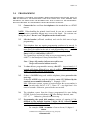
1
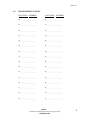
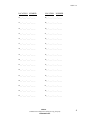
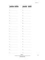
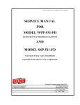
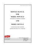
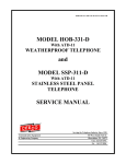
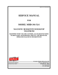
SSP-353-F-61-ADVXFD1.3 Software- ADVXFD1.3-ISSUE4.0
SERVICE MANUAL
FOR
MODEL
SSP-353-F-61
STAINLESS STEEL PANEL TELEPHONE
EQUIPED WITH ADVXFD1.3 SOFTWARE
AND ADVXFD1.3 PCB
Serving the Telephone Industry Since 1930
Communication Equipment
& Engineering Company
519West South Park Street
Okeechobee, FL. 34972
Voice: 863-357-0798
Fax: 8638-357-0006
ISSUE 4.0
IMPORTANT INFORMATION
FOR
CUSTOMER
Please fill in before you continue.
The following information is necessary when calling CEECO for assistance.
MODEL SSP-353-F-61 Equipped With
ADVXFD1.3 Software And PCB.
MODEL NUMBER
SERIAL NUMBER
DATE MANUFACTURED
LOCATION INSTALLED
For us to better serve you, please have this information available when calling for
technical support.
CEECO
Communication Equipment and Engineering Company
519 West South Park Street
Okeechobee, FL. 34972
(863) 357-0798 Voice
(863) 357-0006 Fax
CEECO
Communication Equipment & Engineering Company
PROPRIETARY
2
ISSUE 4.0
TABLE OF CONTENTS
SECTION
PAGE
1.0
GENERAL DESCRIPTION ................................................................................ 4
2.0
PROGRAMMING ................................................................................................ 5
2.11
REMOTE PROGRAMMING ............................................................................. 6
2.12
CHANGING PASS CODES ................................................................................ 7
2.13
NOISE ELIMINATION………………………………………………………....8
2.14
INBOUND CALLS DESIRED............................................................................. 7
3.0
PROGRAMMING TABLES ............................................................................... 8
4.0
OPERATION ...................................................................................................... 11
5.0
RECOMMENDED TOOLS AND TEST EQUIPMENT ................................ 11
6.0
INSTALLATION NOTES AND ASSEMBLY INSTRUCTIONS ................. 12
7.0
TESTING............................................................................................................. 13
8.0
SPECIFICATIONS: ........................................................................................... 13
9.0
PARTS LIST ....................................................................................................... 14
10.0
FCC NOTICE...................................................................................................... 15
11.0
REPAIR AND RETURN INFORMATION..................................................... 16
12.0
WARRANTY POLICY ...................................................................................... 17
CEECO
Communication Equipment & Engineering Company
PROPRIETARY
3
ISSUE 4.0
INTRODUCTION
The practices in this manual provide installation and maintenance information for
CEECO Model SSP-353-F-61 Telephone equipped with ADVXFD1.3 Software
and ADVXFD1.3 Modified PCB.
The information in this manual is subject to change without notification.
For information not included in this manual, please call or write:
CEECO
Customer Service
519 West South Park Street
Okeechobee, FL 34972
(863) 357-0798
(863) 357-0006 FAX
1.0
GENERAL DESCRIPTION
The CEECO Model SSP-353-F-61 Stainless Steel Panel Telephone was designed
with the needs of the Airport Industry specifically in mind. It offers an attractive
yet durable stainless steel finish. It is ideal for installations where the vertical
angle of the mounting surface is very slight. At the same time, it retains the
standard handset and cradle combination, which helps to keep design and repair
cost(s) down. It provides a 4” wide by 4.5” high protected display area for the
placement of printed material. The software for this telephone was designed to
allow up to 100 speed-dial numbers of up to 11 digits each to be utilized.
Provisions are built in to the phone to allow for extra digits to be dialed for PBX
or other access numbers. The user(s) of the phone is able to speed-dial a
telephone number by simply pressing the appropriate 2 keys of the telephone
keypad. To ensure ease of operation for the user(s), a large number keypad has
been installed. The telephone is designed to deter fraud by the nature of the
combined hardware and software design. Incoming calls are not allowed. The
steel panel and chrome plated keypad are vandal resistant. The telephone further
incorporates a 33”, armored cord, hearing aid compatible handset. This extra
length cord provides more comfortable use and access.
This attractive yet
durable telephone meets all of the current needs requested by the Airport industry.
CEECO
Communication Equipment & Engineering Company
PROPRIETARY
4
ISSUE 4.0
2.0
PROGRAMMING
THIS
PBX
EQUIPMENT IS TELEPHONE LINE POWERED. DURING PROGRAMMING THE CENTRAL OFFICE OR
MAY RESPOND TO THE PROGRAMMING CODES WITH VARIOUS BUSY TONES, REORDER TONES
RECORDINGS, ETC. THESE TONES AND RECORDINGS WILL HAVE NO EFFECT ON THE PROGRAMMING.
PLEASE IGNORE THEM. ALL PROGRAMMING IS DONE THROUGH THE UNIT KEYPAD.
2.1
Connect the line cord from the telephone to the intended line or a DTMF
test set.
NOTE: When handling the printed circuit board, be sure not to contact metal
parts, otherwise permanent damage may occur to the board. Use extreme care
during this phase. Do not “rest” the phone on the circuit board.
2.2
Lift the handset (off-hook condition) and wait for dial tone to begin
programming.
2.3
This telephone does not require programming switches to be moved. It
allows programming to be done from the keypad via pass codes. A * key
must always be entered at the end of each programming entry, as will be
noted throughout this programming section. So,
Enter # # # # # * followed by # 4 6 8 3 7 *
The 5 pound keys and star key allow access to programming and the
#46837* is the InterSpace Factory Default Pass Code.
Note: 2 beeps will sound to indicate successful access.
5 beeps will sound to indicate an error.
2.4
To clear all user programmable memory, dial #97*. Approximately 1-2
seconds will elapse followed by a pair of audible tones, indicating the
phone is in a ready state for programming.
2.5
If there is NO PBX being used with the telephone, please proceed to the
next step.
If there IS A PBX being used the telephone, enter # 5 5 followed by the
required access number, followed by *. Example: #559*.
Note: With some systems, a pause is required before the access number is
dialed. In such cases, dial # 5 8 “X” *, where “X” = any digit from 1-9 in
terms of seconds. Otherwise, proceed to the next section.
2.6
The telephone comes from the factory programmed for tone dialing
(DTMF, typical of most telephones). IF pulse dialing is desired, enter
#571*
Otherwise, proceed to the next step.
2.7
Programming the speed dial numbers consists of entering # 3 4,
followed by the intended location (2 digits, 00-99), followed by the
number to be dialed, followed by *.
For example: #3400 + a number of one to eleven (11) digits+*.
CEECO
Communication Equipment & Engineering Company
PROPRIETARY
5
ISSUE 4.0
The programming of the speed dial locations is significantly different than
in the past. Each location must now be accessed by entering #34 before
the actual location, and * at the end of the sequence. Numbers may be
programmed one after another by repeating the steps just previously
mentioned. The telephone does not have to be placed on hook after each
location is programmed.
For example: #34015551212*#340218005558989* will enter the
number 555-1212 into the #01 location and the number 1-800555-8989 into the #02 location.
2.8
An individual number may be erased or changed by just entering #34,
followed by the appropriate location (00-99), followed by the new number
to be dialed OR no number (erased), followed by *. Example #3402*
would erase the contents of speed dial location 2. Entering #3402 + a
number to be dialed, + *, would program that new number.
2.9
Locations 00 - 99 are the speed dialing memory locations. Log the
numbers programmed into Section 3.0 Programming Tables for future
reference.
2.10
When programming is complete, hang up the phone (“on-hook
condition).
2.11 REMOTE PROGRAMMING
This telephone is equipped with the necessary electronics and software to allow
remote programming. If the telephone lines are set up to allow direct access to
the telephone, then the programmer does not need to physically be with the phone
to program it. To allow this, the DIP switch at position S2 of the printed circuit
board must be set with positions 1 & 3 “ON”, and position 2 “OFF”, as follows:
CEECO
Communication Equipment & Engineering Company
PROPRIETARY
6
ISSUE 4.0
From another telephone, or with CEECO’s special line of Smart Tools,
dial the telephone number for the telephone that is intended to be programmed
remotely.
The telephone will automatically answer itself after 5-6 rings and will emit three
tones indicating it has answered.
In order to access programming, enter # 4 6 8 3 7 * Interspace Code
Or, # 2 6 6 8 7 *, which is a service rep factory default code. Two beeps will
indicate successful access. From here, all programming is the same as
described from section 2.4 forward, except that the phone MUST be hung up
remotely by entering # 3 6 *.
2.12
CHANGING PASS CODES
This telephone has a contractor pass code that can be changed by both the owner
(Interspace) and the contractor (rep). Interspace should change the default
contractor/rep pass code (26687) and only give it to the contractor servicing the
telephone.
Example: Dial # 3 5 x x x x x * where “x” equals any digit 0-9
So, # 3 5 8 3 5 6 9 * changes pass code to 83569.
In order to change the Interspace default pass code, enter # 3 1 x x x x x *, as
shown in the above example.
2.13
Some locations are extremely noisy, making it hard to hear on the
telephone. This unit allows a computer-controlled noise filtering of the
handset to be activated to help battle the extreme background noise. In
order to activate this noise elimination feature, enter # 5 9 1 *.
2.14
The telephone comes from the factory set to block inbound calls. If
Inbound Calls Are Desired, enter # 5 4 1 *.
CEECO
Communication Equipment & Engineering Company
PROPRIETARY
7
ISSUE 4.0
3.0
PROGRAMMING TABLES
LOCATION NUMBER
LOCATION NUMBER
00_ _ - _ _ _ - _ _ _ - _ _ _ _
16_ _ - _ _ _ - _ _ _ - _ _ _ _
01 _ _ - _ _ _ - _ _ _ - _ _ _ _
17_ _ - _ _ _ - _ _ _ - _ _ _ _
02_ _ - _ _ _ - _ _ _ - _ _ _ _
18_ _ - _ _ _ - _ _ _ - _ _ _ _
03_ _ - _ _ _ - _ _ _ - _ _ _ _
19_ _ - _ _ _ - _ _ _ - _ _ _ _
04_ _ - _ _ _ - _ _ _ - _ _ _ _
20_ _ - _ _ _ - _ _ _ - _ _ _ _
05_ _ - _ _ _ - _ _ _ - _ _ _ _
21_ _ - _ _ _ - _ _ _ - _ _ _ _
06_ _ - _ _ _ - _ _ _ - _ _ _ _
22_ _ - _ _ _ - _ _ _ - _ _ _ _
07_ _ - _ _ _ - _ _ _ - _ _ _ _
23_ _ - _ _ _ - _ _ _ - _ _ _ _
08_ _ - _ _ _ - _ _ _ - _ _ _ _
24_ _ - _ _ _ - _ _ _ - _ _ _ _
09_ _ - _ _ _ - _ _ _ - _ _ _ _
25_ _ - _ _ _ - _ _ _ - _ _ _ _
10_ _ - _ _ _ - _ _ _ - _ _ _ _
26_ _ - _ _ _ - _ _ _ - _ _ _ _
11_ _ - _ _ _ - _ _ _ - _ _ _ _
27_ _ - _ _ _ - _ _ _ - _ _ _ _
12_ _ - _ _ _ - _ _ _ - _ _ _ _
28_ _ - _ _ _ - _ _ _ - _ _ _ _
13_ _ - _ _ _ - _ _ _ - _ _ _ _
29_ _ - _ _ _ - _ _ _ - _ _ _ _
14_ _ - _ _ _ - _ _ _ - _ _ _ _
30_ _ - _ _ _ - _ _ _ - _ _ _ _
15_ _ - _ _ _ - _ _ _ - _ _ _ _
31_ _ - _ _ _ - _ _ _ - _ _ _ _
CEECO
Communication Equipment & Engineering Company
PROPRIETARY
8
ISSUE 4.0
LOCATION NUMBER
LOCATION
32_ _ - _ _ _ - _ _ _ - _ _ _ _
48_ _ - _ _ _ - _ _ _ - _ _ _ _
33_ _ - _ _ _ - _ _ _ - _ _ _ _
49_ _ - _ _ _ - _ _ _ - _ _ _ _
34_ _ - _ _ _ - _ _ _ - _ _ _ _
50_ _ - _ _ _ - _ _ _ - _ _ _ _
35_ _ - _ _ _ - _ _ _ - _ _ _ _
51_ _ - _ _ _ - _ _ _ - _ _ _ _
36_ _ - _ _ _ - _ _ _ - _ _ _ _
52_ _ - _ _ _ - _ _ _ - _ _ _ _
37_ _ - _ _ _ - _ _ _ - _ _ _ _
53_ _ - _ _ _ - _ _ _ - _ _ _ _
38_ _ - _ _ _ - _ _ _ - _ _ _ _
54_ _ - _ _ _ - _ _ _ - _ _ _ _
39_ _ - _ _ _ - _ _ _ - _ _ _ _
55_ _ - _ _ _ - _ _ _ - _ _ _ _
40_ _ - _ _ _ - _ _ _ - _ _ _ _
56_ _ - _ _ _ - _ _ _ - _ _ _ _
41_ _ - _ _ _ - _ _ _ - _ _ _ _
57_ _ - _ _ _ - _ _ _ - _ _ _ _
42_ _ - _ _ _ - _ _ _ - _ _ _ _
58_ _ - _ _ _ - _ _ _ - _ _ _ _
43_ _ - _ _ _ - _ _ _ - _ _ _ _
59_ _ - _ _ _ - _ _ _ - _ _ _ _
44_ _ - _ _ _ - _ _ _ - _ _ _ _
60_ _ - _ _ _ - _ _ _ - _ _ _ _
45_ _ - _ _ _ - _ _ _ - _ _ _ _
61_ _ - _ _ _ - _ _ _ - _ _ _ _
46_ _ - _ _ _ - _ _ _ - _ _ _ _
62_ _ - _ _ _ - _ _ _ - _ _ _ _
47_ _ - _ _ _ - _ _ _ - _ _ _ _
63_ _ - _ _ _ - _ _ _ - _ _ _ _
NUMBER
CEECO
Communication Equipment & Engineering Company
PROPRIETARY
9
ISSUE 4.0
LOCATION NUMBER
LOCATION
NUMBER
64_ _ - _ _ _ - _ _ _ - _ _ _ _
82_ _ - _ _ _ - _ _ _ - _ _ _ _
65_ _ - _ _ _ - _ _ _ - _ _ _ _
83_ _ - _ _ _ - _ _ _ - _ _ _ _
66_ _ - _ _ _ - _ _ _ - _ _ _ _
84_ _ - _ _ _ - _ _ _ - _ _ _ _
67_ _ - _ _ _ - _ _ _ - _ _ _ _
85_ _ - _ _ _ - _ _ _ - _ _ _ _
68_ _ - _ _ _ - _ _ _ - _ _ _ _
86_ _ - _ _ _ - _ _ _ - _ _ _ _
69_ _ - _ _ _ - _ _ _ - _ _ _ _
87_ _ - _ _ _ - _ _ _ - _ _ _ _
70_ _ - _ _ _ - _ _ _ - _ _ _ _
88_ _ - _ _ _ - _ _ _ - _ _ _ _
71_ _ - _ _ _ - _ _ _ - _ _ _ _
89_ _ - _ _ _ - _ _ _ - _ _ _ _
72_ _ - _ _ _ - _ _ _ - _ _ _ _
90_ _ - _ _ _ - _ _ _ - _ _ _ _
73_ _ - _ _ _ - _ _ _ - _ _ _ _
91_ _ - _ _ _ - _ _ _ - _ _ _ _
74_ _ - _ _ _ - _ _ _ - _ _ _ _
92_ _ - _ _ _ - _ _ _ - _ _ _ _
75_ _ - _ _ _ - _ _ _ - _ _ _ _
93_ _ - _ _ _ - _ _ _ - _ _ _ _
76_ _ - _ _ _ - _ _ _ - _ _ _ _
94_ _ - _ _ _ - _ _ _ - _ _ _ _
77_ _ - _ _ _ - _ _ _ - _ _ _ _
95_ _ - _ _ _ - _ _ _ - _ _ _ _
78_ _ - _ _ _ - _ _ _ - _ _ _ _
96_ _ - _ _ _ - _ _ _ - _ _ _ _
79_ _ - _ _ _ - _ _ _ - _ _ _ _
97_ _ - _ _ _ - _ _ _ - _ _ _ _
80_ _ - _ _ _ - _ _ _ - _ _ _ _
98_ _ - _ _ _ - _ _ _ - _ _ _ _
81_ _ - _ _ _ - _ _ _ - _ _ _ _
99_ _ - _ _ _ - _ _ _ - _ _ _ _
CEECO
Communication Equipment & Engineering Company
PROPRIETARY
10
ISSUE 4.0
4.0
OPERATION
When the phone is connected to the phone line and programmed according to
section 2, the phone operates as follows:
5.0
4.1
When the phone is lifted off hook, dial tone is heard and the keypad is
operational. Before and during dialing, the transmitter is turned off.
4.2
To dial a desired number, the user simply presses the two keys
corresponding to the desired number. These two keys will cause the
phone to automatically dial the programmed number (as accomplished in
section 2.0) and the transmitter turns on. The keypad is available
for use once speed dial number is accessed.
4.3
At the completion of the call the user places the handset back on the
cradle, which allows the telephone to reset for the next user.
RECOMMENDED TOOLS AND TEST EQUIPMENT
DTMF Test Set
Volt/Ohm Meter
1/4" Nut Driver
Flat Blade Screw Driver
Security Tool 301-064
CEECO
Communication Equipment & Engineering Company
PROPRIETARY
11
ISSUE 4.0
6.0
INSTALLATION NOTES AND ASSEMBLY INSTRUCTIONS
6.1
In order to install printed material in the instruction window, please locate
the 8 retaining nuts on the rear of the telephone assembly. Extreme
caution must be used in removing the nuts, so as not to touch the printed
circuit board(s). Doing so may cause permanent damage to the boards.
After carefully removing the nuts, remove the instruction window on the
front side of the telephone assembly. Install the desired material and
carefully replace the window and nuts.
6.2
Run the telephone line wire the telephone assembly and terminate on the
RJ11C terminal block, as depicted on the following page. Additionally, an
approximately 10’ green grounding wire is provided for grounding the
chassis. In order to be effective, this must be attached to a true earth
ground.
6.3
Plug the modular line cord from the telephone assembly into the RJ11C
modular jack provided.
6.4
Dress the telephone line cord away from the mounting holes and seat the
telephone assembly onto the mounting surface.
6.5
Secure the telephone assembly to the mounting surface with the chosen
hardware.
6.6
The use of a gas tube station protector is recommended for grounding.
The station ground should not exceed 50 ohms.
WARNING
A.
Never install telephone wiring during a lightning storm.
B.
Never install telephone jacks in wet locations unless the
jack is specifically designed for wet locations.
C.
Never touch uninsulated telephone wires or terminals,
unless the telephone line has been disconnected at the
network interface.
D.
Use caution when installing or modifying telephone lines.
CEECO
Communication Equipment & Engineering Company
PROPRIETARY
12
ISSUE 4.0
7.0
8.0
TESTING
7.1
Connect the modular line cord to a working telephone line or a DTMF test
set.
7.2
Lift the handset and dial the two-digit code for each location programmed.
Verify that the numbers dial as intended. The telephone must be placed on
hook (new dial tone) before testing each number.
SPECIFICATIONS:
INPUT POWER:
C.O. Line Powered
LOOP CURRENT:
23Ma min. 80Ma max.(48 Volt loop)
IMPEDANCE:
600 ohms
SIGNALING:
DTMF, 70ms tone, 50ms spacing
HEARING AID
COMPATIBLE:
Meets EIA standards
ENVIRONMENTAL:
Temperature: 0°C to 50°C
Humidity:
20%-90%
PROGRAMMING:
Via DTMF Keypad
TELEPHONE PANEL:
Brushed 14 gauge Stainless Steel
DIMENSIONS:
10" Wide x 11" High x 4 1/4" Deep
(Handset on hook).
MOUNTING:
Surface Mount- Vertical Angle >19°
WEIGHT:
Approximately 5 lbs.
MEMORY RETENTION:
Non-volatile
FCC REGISTRATION:
BW88T7-13823-TE-T
CEECO
Communication Equipment & Engineering Company
PROPRIETARY
13
ISSUE 4.0
9.0
PARTS LIST
QUANTITY
PART NUMBER
DESCRIPTION
1
705-103
Keypad
1
ADVXFD1.3
PCB
1
301-016-33
Handset with armored cord
1
301-592
Hookswitch cradle (mag)
1
SSP-353-F-61
Stainless Steel Panel
1
301-051
Modular Jack
1
301-018
30" Modular Cord
1
301-030
Instruction Card Kit
1
Accessories:
1
ADVXFD1.3 Software
301-064
Security tool
CEECO
Communication Equipment & Engineering Company
PROPRIETARY
14
ISSUE 4.0
10.0
FCC NOTICE
10.1
FCC REGISTRATION AND REPAIR INFORMATION
Your new telephone has been registered with the Federal Communication
Commission (FCC) in accordance with Part 68 of its rules. The FCC
requires that you be advised of certain requirements involving the use of
this telephone.
10.2
CONNECTION WITH THE NATIONWIDE TELEPHONE
NETWORK
The FCC requires that you connect this telephone to the Nationwide
Telephone Network through a registered jack provided by the telephone
company in your area. This jack is a modular outlet, which you can order
from your local telephone company.
10.3
NOTIFICATION TO THE TELEPHONE COMPANY
Before connecting this telephone, the FCC requires that you notify your
local telephone company business office. The number is in the front of
your phone book.
Tell them: The "line" to which you will connect the telephone (that is,
your phone number) and the telephone's FCC registration number and
ringer equivalence number. These numbers are listed in section 9.00.
The FCC further requires that you notify your local telephone company
when permanently disconnecting this telephone.
CEECO
Communication Equipment & Engineering Company
PROPRIETARY
15
ISSUE 4.0
11.0
REPAIR AND RETURN INFORMATION
11.1
WARRANTY REPAIR
Any device returned requiring warranty service; repair or credit must be
accompanied with a "Return Material Authorization" (RMA) FORM. It
must include return shipping instructions, original purchase order number
and special marking instruction. A description of the trouble observed
must be attached to the defective unit. This information must be inside the
shipping container.
11.2
DIRECT ALL INQUIRES TO:
CEECO
Repair Department
519 West South Park Street
Okeechobee, FL. 34972
(863) 357-0798
11.3
NON-WARRANTY REPAIR
CEECO will repair equipment out of warranty for a set charge plus parts.
The customer must pay the shipping costs both directions.
11.4
RETURN FOR CREDIT
Material may be returned for credit only with prior approval. Material
authorized for return is subject to a 20% restocking charge based on the
manufacturer’s list price. Return RMA must be requested no later than 30
days after original shipment. Returns are not granted on custom orders
unless otherwise specified.
CEECO
Communication Equipment & Engineering Company
PROPRIETARY
16
ISSUE 4.0
12.0
WARRANTY POLICY
12.1
GENERAL
CEECO products are guaranteed to be free of defects in material and
workmanship for a period of 365 days from the date of original purchase.
CEECO's obligation under this warranty is limited to repair or
replacement of any part found to be defective by CEECO. Under no
circumstances shall CEECO be liable for loss, damage, cost of repair or
consequential damages of any kind which have been caused by neglect,
abuse, acts of GOD or improper operation of equipment.
12.2
PRINTED CIRCUIT BOARDS
Printed circuit boards should not be repaired in the field. If a unit is found
to be faulty, replace it with another unit and return the faulty unit to
CEECO for repair. Modifications by any one other than CEECO will void
the warranty.
CEECO
Communication Equipment & Engineering Company
PROPRIETARY
17