1
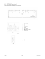
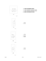
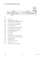
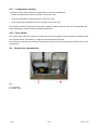
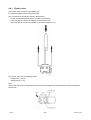
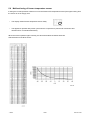
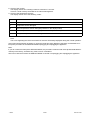
SERVICE MANUAL
REFRIGERATION
REFRIGERATORS
© Electrolux Home Products S.p.A.
Spares Operations Italy
Corso lino Zanussi, 30
I - 33080 Porcia (PN)
Fax +39 0434 394096
Publication no.
599 38 43-56
EN
S.O.I.
Edition: 11.2006
with
electric valve
and
electronic
ERF2000
DIGITS
FACTORY: ZS
- ITZAA
1/26
599 38 43-56
CONTENT
1
INTRODUCTION ....................................................................................................................................... 3
2
REFRIGERATION CIRCUIT...................................................................................................................... 5
3
ELECTRIC WIRING................................................................................................................................... 6
4
COMPONENTS ......................................................................................................................................... 8
4.1 Control panel ..................................................................................................................................... 8
4.2 Electronic boards ............................................................................................................................... 9
4.2.1 ERF2000 Power board ........................................................................................................... 10
4.2.2 ERF2000 DIGITS Display board............................................................................................. 12
4.3 Cooler and freezer compartments ................................................................................................... 13
4.3.1 Temperature sensors.............................................................................................................. 14
4.3.2 Door switch ............................................................................................................................. 14
4.4 Compressor compartment ............................................................................................................... 14
4.4.1 Electric valve........................................................................................................................... 15
5
MAIN FUNCTIONS .................................................................................................................................. 16
5.1
5.2
5.3
5.4
5.5
5.6
6
Normal .............................................................................................................................................
FROSTMATIC Function (rapid freezing) .........................................................................................
COOLMATIC Function (rapid cooling).............................................................................................
HOLIDAY Function (valid only for the cooler) ..................................................................................
Malfunctioning of cooler air temperature sensor..............................................................................
Malfunctioning of freezer temperature sensor .................................................................................
16
17
17
17
18
19
ALARMS .................................................................................................................................................. 20
6.1 Freezer compartment temperature alarm ........................................................................................ 20
7
SPECIAL FUNCTIONS............................................................................................................................ 21
7.1 Service Mode...................................................................................................................................
7.1.1 Starting Service Mode ............................................................................................................
7.1.2 Exiting Service Mode ..............................................................................................................
7.1.3 Functions of the Service Mode ...............................................................................................
7.2 DEMO MODE ..................................................................................................................................
7.2.1 Start DEMO MODE.................................................................................................................
7.2.2 Exit DEMO MODE ..................................................................................................................
7.2.3 Functions of the DEMO MODE...............................................................................................
8
21
21
21
21
23
23
23
23
ACCESSIBILITY ...................................................................................................................................... 24
8.1 Control panel ................................................................................................................................... 24
9
DISPLAY SYMBOLS ............................................................................................................................... 25
9.1 Cooler compartment ........................................................................................................................ 25
9.2 Freezer compartment ...................................................................................................................... 26
- ITZAA
2/26
599 38 43-56
1
INTRODUCTION
This manual describes the refrigerators with electric valve and ERF2000 DIGITS electronic produced in the
Susegana factory called ZS.
These models feature:
-
static (static freezer, static cooler)
total built-in
DOOR ON DOOR door system
single-compressor
electronic control (electronic board ERF2000)
electric valve
digit display
They are appliances (KBI290DVIT) with the following PNCs:
PNC
MODEL
BRAND
925701653
JKG9499
Juno-Electrolux
925701654
SC91840-5I
AEG-Electrolux
925701655
SC81840-5I
AEG-Electrolux
925701656
SC81840-5I
AEG-Electrolux
925701659
ERO2923
Electrolux
925701660
ERO2924
Electrolux
925701661
JKG9499
Juno-Electrolux
925701662
SC91840-5I
AEG-Electrolux
925701663
SC91843-5I
AEG-Electrolux
925701664
463.688-2
Privileg
925701665
ERO2923
Electrolux
925701666
ERO2923
Electrolux
925701667
DRC629JE
De Dietrich
925701668
IKE318-5-2
Küppersbusch
925701669
DRC629JE
De Dietrich
925701670
IKE318-5-2
Küppersbusch
925701671
JCG94180
Juno-Electrolux
The controls of the appliance are inserted inside the upper crosspiece.
The power control board is ERF2000.
The user interface board is ERF2000 (DIGIT display).
The appliance has a single-compressor and an electric valve is installed to simulate the operation of a twocompressor.
It is possible to switch off only the cooler compartment and let the freezer operate, but not vice versa.
- ITZAA
3/26
599 38 43-56
The temperatures regulation is the following:
•
•
from +8 to +2 °C for the cooler;
from -15 to -24 °C for the freezer.
The DIGIT display enables to show the temperatures of the two compartments.
The appliance has the following functions:
•
•
•
•
rapid freezing;
rapid cooling;
freezer temperature alarm,
cooler compartment holiday.
The appliance consists of the following compartments:
•
•
freezer;
cooler.
The evaporating circuit consists of:
•
•
roll bond plate evaporator (freezer);
tube evaporator (cooler compartment).
Key:
A = control panel
B = cooler compartment
C = freezer compartment
- ITZAA
4/26
599 38 43-56
2
REFRIGERATION CIRCUIT
Key:
1.
2.
3.
4.
5.
6.
7.
8.
compressor;
condenser;
anti-condensation coil;
dehydrator filter;
electric valve;
tube evaporator (cooler compartment);
plate evaporator (freezer compartment);
exchanger.
The electric valve has 2 outlet capillaries to power:
•
cooler + freezer
or
•
only the freezer.
- ITZAA
5/26
599 38 43-56
3
ELECTRIC WIRING
(Check the specific diagram for each model!)
- ITZAA
6/26
599 38 43-56
Key:
2.
compressor
13.
lamp
31.
electric valve
28.
running capacitor (if featured)
41.
ERF2000 power board
a.
yellow-green
b.
brown
c.
blue
d.
white
e.
black
- ITZAA
7/26
599 38 43-56
4
COMPONENTS
4.1 Control panel
Key:
Cooler compartment
A.
B.
C.
D.
E.
F.
G.
cooler ON/OFF indicator LED
cooler ON/OFF button
cooler temperature increase button (+)
cooler temperature displaying
cooler temperature decrease button (-)
COOLMATIC Function LED (rapid cooling)
COOLMATIC function button (rapid cooling)
Freezer compartment
H.
I.
J.
K.
L.
M.
N.
O.
P.
ON/OFF indicator LED refrigeratore+freezer
ON/OFF button cooler+freezer
freezer temperature increase button (+)
freezer temperature displaying
freezer temperature decrease button (-)
FROSTMATIC Function LED (rapid freezing)
FROSTMATIC function button (rapid freezing)
alarm pilot lamp LED
alarm deactivation button
- ITZAA
8/26
599 38 43-56
4.2 Electronic boards
The electronic board of the appliance consists of:
1. ERF2000 power board
2. ERF2000 DIGITS display board
The two electronic boards are connected by means of a flat cable with a connector; therefore, the two boards
are available singularly as spare part.
- ITZAA
9/26
599 38 43-56
4.2.1 ERF2000 Power board
- View of the electronic board (side of components):
1.
2.
3.
4.
5.
6.
7.
8.
9.
earth contact
free
line
compressor
neutral
lamp neutral
lamp
neutral electric valve
electric valve
1. free
2. free
- ITZAA
10/26
599 38 43-56
1.
2.
3.
4.
5.
6.
cooler air temperature sensor
cooler air temperature sensor
cooler evaporator temperature sensor
cooler evaporator temperature sensor
freezer air temperature sensor
freezer air temperature sensor
1. free
2. free
1.
2.
3.
4.
free
free
free
free
1. free
2. free
- ITZAA
11/26
599 38 43-56
4.2.2 ERF2000 DIGITS Display board
Key:
SW1
= reed element
SW2
= ON/OFF button cooler+freezer
SW3
= FROSTMATIC function button (rapid freezing)
SW4
= freezer temperature increase button (+)
SW5
= freezer temperature decrease button (-)
SW6
= cooler ON/OFF button
SW7
= COOLMATIC function button (rapid cooling)
SW8
= cooler temperature increase button (+)
SW9
= cooler temperature decrease button (-)
SW10
= alarm deactivation button
DGT1
= cooler display
DGT2
= freezer display
DL1
= COOLMATIC function LED (rapid cooling)
DL2
= FROSTMATIC function LED (rapid freezing)
DL3
= alarm pilot lamp LED
DL4
= LED sign + cooler
DL5
= ON/OFF indicator LED cooler
DL6
= LED sign - freezer
DL7
= ON/OFF indicator LED cooler+freezer
- ITZAA
12/26
599 38 43-56
4.3 Cooler and freezer compartments
Key:
A. freezer air temperature sensor;
B. cooler air temperature sensor;
C. cooler evaporator temperature sensor.
1. cooler door magnet;
2. display board reed element.
- ITZAA
13/26
599 38 43-56
4.3.1 Temperature sensors
3 NTC sensors are used to detect the temperatures of the two compartments:
•
freezer air temperature sensor A (located on the freezer cell);
•
cooler air temperature sensor B (located on the cooler cell);
•
cooler evaporator temperature sensor C (located on the cooler cell).
The sensors A, B and C feature the foamed cable inside the cabinet, therefore they are not replaceable (for
further information, please see Service Bulletin 599374122).
4.3.2 Door switch
The control of the cooler door opening is carried out by using the magnetic switch located on the display board.
The magnetic switch is activated by a magnet located inside the cooler door.
The control does not imply the activation of the open door alarm, but it is used to light up the lamp of the cooler
compartment.
4.4 Compressor compartment
Key:
A. compressor
B. electric valve
- ITZAA
14/26
599 38 43-56
4.4.1 Electric valve
The electric valve is of the 3-way bistable type.
It is supplied together with the dehydrator filter.
The connections of the electric valve are the following:
-
central hose with dehydrator filter to connect the condenser;
side hose (GS) to connect the capillary of the freezer circuit;
side hose (KS) to connect the capillary of the cooler+freezer circuit.
The electric valve has the following values:
-
voltage 220 V - 50 Hz
response time <1 sec
Note:
Comply with the electric connections and do not invert the polarity (the 2 terminals FAST-ON have different
dimensions).
- ITZAA
15/26
599 38 43-56
5
MAIN FUNCTIONS
5.1 Normal
Warning: Unplug the appliance before operating.
In case of first switching on with a freezer compartment temperature higher than 10 °C, the appliance operates
with a test cycle (for the factory) for a maximum time of about 1,5 hours.
In this period do not perform tests for the correct operation of the appliance, since the loads of the appliance
are activated only for internal check (compressor and electric valve).
When the appliance is off then:
•
•
the compressor is off;
the displays are off.
Pushing the ON/OFF button, the displays switch on with the following displaying:
•
•
•
+ symbol on cooler display;
flashing digits of the freezer;
freezer temperature alarm LED (buzzer active).
Push the alarm deactivation button to deactivate the buzzer.
Regulate the temperatures of the compartments so as to set the following values:
•
•
about +5 °C in the cooler;
about -18 °C in the freezer.
- ITZAA
16/26
599 38 43-56
5.2 FROSTMATIC Function (rapid freezing)
The FROSTMATIC function (rapid freezing) is activated by pushing the relative button, therefore:
•
•
The pilot lamp relative to the FROSTMATIC function lights up;
The compressor operates in thermostatic conditions and not continuously (like the temperature knob was
on max. position) for a duration of about 52 hours, and then it deactivates automatically.
To deactivate the FROSTMATIC function push the relative button.
5.3 COOLMATIC Function (rapid cooling)
The COOLMATIC function (rapid cooling) is activated by pushing the relative button, therefore:
•
•
The pilot lamp relative to the COOLMATIC function lights up;
The compressor operates in thermostatic conditions and not continuously (like the temperature knob was
on max. position) for a duration of about 6 hours, and then it deactivates automatically.
To deactivate the COOLMATIC function push the relative button.
5.4 HOLIDAY Function (valid only for the cooler)
The HOLIDAY function is activated when the customer does not want to use temporary the cooler.
In this case it is not necessary to leave the cooler door open, because a 15 °C temperature is automatically set
to avoid the formation of bad odours inside.
To activate the HOLIDAY function push button + (temperature increase) till letter H is shown in the cooler display.
Obviously the cooler must be empty because the 15 °C temperature does not allow the preservation of the most
common food.
- ITZAA
17/26
599 38 43-56
5.5 Malfunctioning of cooler air temperature sensor
If during the normal operation a failure occurs to the cooler NTC temperature sensor (the signal coming from
the sensor is out of range), then:
•
The display shows cooler temperature sensor faulty.
•
The appliance operates with preset cycle when the compressor is powered for 40 minutes and
remains off for 40 minutes alternatively.
When the sensor operates again normally, the above described conditions terminate.
Characteristics of the NTC sensor:
- ITZAA
18/26
599 38 43-56
5.6 Malfunctioning of freezer temperature sensor
If during the normal operation a failure occurs to the freezer NTC temperature sensor (the signal coming from
the sensor is out of range), then:
•
The display shows freezer temperature sensor faulty.
•
The appliance operates with preset cycle when the compressor is powered for 40 minutes and
remains off for 40 minutes alternatively.
When the sensor operates again normally, the above described conditions terminate.
Characteristics of the NTC sensor:
- ITZAA
19/26
599 38 43-56
6
ALARMS
6.1 Freezer compartment temperature alarm
When the freezer compartment reaches -11 °C, the temperature alarm activates:
•
The display digits flash.
•
The temperature alarm pilot lamp light up.
•
The buzzer sounds.
Push the alarm deactivation button to deactivate the buzzer.
When normal conditions are reset (after a power failure):
•
The acoustic signal deactivates.
•
The temperature alarm pilot lamp remains on.
•
The display digits still flash.
Pushing the alarm deactivation button:
•
The highest temperature reached in the freezer compartment is displayed for 5 minutes.
•
The alarm pilot lamp switches off.
•
The display digits do not flash anymore.
- ITZAA
20/26
599 38 43-56
7
SPECIAL FUNCTIONS
7.1 Service Mode
7.1.1 Starting Service Mode
To start the procedure, perform the following operations:
1.
2.
3.
4.
5.
Connect the plug to the socket.
Switch on the appliance with the ON/OFF button.
Open the doors of the appliance.
Switch the appliance off with the ON/OFF button.
Within the first 10 seconds hold down simultaneously the two buttons “FROSTMATIC function (rapid freezing)” and “alarm deactivation”.
The confirmation of the procedure start occurs with the acoustic signalling of the buzzer which emits a long
beep and with the lighting up of all segments of the display.
7.1.2 Exiting Service Mode
The procedure terminates when one of the following operations is carried out:
a. The plug is detached from the socket and reconnected.
b. 40 minutes have elapsed and no button has been pushed.
c. The last phase of the procedure has been reached.
7.1.3 Functions of the Service Mode
Press the button “FROSTMATIC function (rapid freezing)” or “alarm deactivation” to skip to the following phase
of the procedure.
Prsss the “ON/OFF” button to activate/deactivate the loads (compressor, defrosting heater, lamp, fan and air
flow regulator damper).
List of the phases of the SERVICE MODE:
1. All segments of the display are on.
2. All segments of the displays are off.
3. The number 0 is shown on the display and the load controlled by ACS TH1 [compressor] is checked.
To activate/deactivate the load press the button “ON/OFF” (the load is activated when the rapid freezing
FROSTMATIC function pilot lamp and the alarm pilot lamp light up).
4. The number 1 is shown on the display and the load controlled by ACS TH2 [electric valve] is checked.
To activate/deactivate the load press the button “ON/OFF” (the electric valve switches from one side to the
other and it is possible to hear a click).
5. The number 2 is shown on the display and the laod controlled by ACS TH3 [lamp] is checked.
To activate/deactivate the load press the button “ON/OFF” (the load is activated when the rapid freezing
FROSTMATIC function pilot lamp and the alarm pilot lamp light up).
6. The number 3 is shown on the display and the load controlled by ACS TH4 [not used in this appliance] is
checked.
To activate/deactivate the load press the button “ON/OFF” (the load is activated when the rapid freezing
FROSTMATIC function pilot lamp and the alarm pilot lamp light up).
Note:
When the procedure skips to the following phase pressing the button “FROSTMATIC function (rapid freezing)” or “alarm deactivation”, the laod keeps its status (for example, if the compressor had been activated,
it will remain on also in the subsequent phases); in this way it is possible to check the loads simultaneously.
7. Check of the doors.
The display digits correspond to the doors: the unit digits correspond to the cooler door, while the ten digits
correspond to the freezer door.
If the relative door is closed, the displayed digit is 0 otherwise is 1.
- ITZAA
21/26
599 38 43-56
8. Check of the counter.
The display shows an increasing number at intervals of 1 second.
This is a counter used by the board for its internal management.
9. Check of the temperature sensors.
The display shows one of the following codes:
Code
DESCRIPTION
E0
No error
E1
Evaporator sensor damaged
E2
Room temperature sensor damaged (installed on the display board)
E4
Room temperature sensor damaged (installed on the power board)
E5
0 degree compartment sensor damaged
Note:
The errors regarding the cooler and freezer air sensors are already displayed during the normal operation.
At this point all the phases necessary to chcek the loads have been displayed, therefore it is advisable to interrupt the procedure of the SERVICE MODE unplugging and replugging the appliance.
Note:
If you do not want to interrupt the SERVICE MODE, the procedure continues with some phases dedicated exclusively to the factory, therefore they must not to be considered.
Also in this case the exit from the SERVICE MODE is carried out unplugging and replugging the appliance.
- ITZAA
22/26
599 38 43-56
7.2 DEMO MODE
The DEMO MODE function is intended only for the commercial activity and not for the user.
The internal temperature of the appliance, measured by the air sensors, must be higher than +10 °C so as the
function can be activated.
7.2.1 Start DEMO MODE
To start the procedure, hold down the ON/OFF button cooler+freezer and the freezer temperature decrease
button for more than 5 seconds.
The display digits flash every about 4 seconds.
7.2.2 Exit DEMO MODE
To exit the procedure, hold down the ON/OFF button cooler+freezer and the freezer temperature decrease button for more than 5 seconds or unplug the appliance.
7.2.3 Functions of the DEMO MODE
The procedure is used only for show in the selling points and allows selecting the temperatures without activating the loads (compressor and electric valve).
The displays show:
•
•
+ 5 °C for the cooler compartment (flashing display);
-18 °C for the freezer compartment (flashing display).
By pushing the temperature regulation buttons, the displays show the temperatures that can be set (flashing
display).
The internal light switches on when the cooler door is opened.
By pushing the cooler ON/OFF button it is possible to simulate the switching off of the cooler compartment (the
lamp is off).
- ITZAA
23/26
599 38 43-56
8
ACCESSIBILITY
Warning: Disconnect the appliance from the electric power before operating with the
appliance.
8.1 Control panel
To access the control panel and its components (power and display boards) perform the following operations
in sequence:
a. Open the cooler door.
b) View of the control panel of the upper crosspiece.
c) Remove the programme plate removing the 2
screw covers and the 2 fixing screws.
d) Remove the transparent foil and extract the control support.
e) View of the power board.
- ITZAA
24/26
599 38 43-56
9
DISPLAY SYMBOLS
9.1 Cooler compartment
DISPLAY
- ITZAA
DIGITS
DESCRIPTION
NOT FLASHING
It indicates the cooler temperature with normal function
[from +2 to +8].
FLASHING
It indicates the cooler temperature with DEMO MODE function [from +2 to +8].
NOT FLASHING
It indicates the HOLIDAY function of the cooler compartment [15 °C].
NOT FLASHING
It indicates the malfunctioning of cooler air temperature
sensor.
NOT FLASHING
It indicates incompatibility between the electronic boards.
Remedy: check the spare part nos. of the electronic
boards.
NOT FLASHING
It indicates Eeprom parameter writing/reading error.
Remedy: replace both electronic boards (power and display).
25/26
599 38 43-56
9.2 Freezer compartment
DISPLAY
- ITZAA
DIGITS
DESCRIPTION
NOT FLASHING
It indicates the freezer temperature with normal function
[from -15 to -24].
FLASHING
It indicates the freezer temperature with DEMO MODE
function [from -15 to -24].
NOT FLASHING
It indicates the malfunctioning of freezer air temperature
sensor.
NOT FLASHING
It indicates incompatibility between the electronic boards.
Remedy: check the spare part nos. of the electronic boards.
NOT FLASHING
It indicates Eeprom parameter writing/reading error.
Remedy: replace both electronic boards (power and display).
26/26
599 38 43-56