1
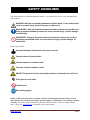
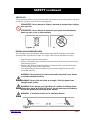
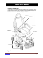
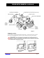
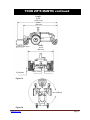
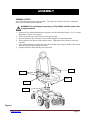
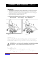
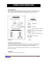
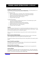
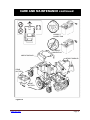
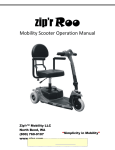
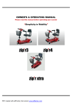
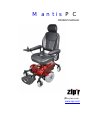
Mantis PC OWNER’S MANUAL (800)760-9107 www.zipr.com SAFETY GUIDELINES The symbols below are used throughout this manual. It is important for you to review and understand these symbols. WARNING! Indicates a potentially hazardous situation which, if not avoided could result in personal injury, product damage, or malfunction. MANDATORY! Indicates that these actions should be performed as specified and failure to perform mandatory actions can cause personal injury, product damage, or malfunction. PROHIBITED! Indicates that such actions should not be performed at any time. Performing a prohibited action can cause personal injury, product damage, or malfunction. Other safety symbols: Read and follow the information in the owner’s manual. Potential electrical hazard exists! Potential explosive condition exists! Corrosive chemical condition exists! EMI-RFI This product has been tested and passed at an immunity level of 20 V/m. Pinch point or crush point. Contains lead. Wear safety goggles. Failure to follow the instructions, warnings, and notes in this manual and those located on your Zip'r Mantis can result in personal injury, product damage or malfunction, and void Zipr's product warranty. Please note that the information contained in this document is subject to change without notice. Please see www.zipr.com for updated copies of this manual. www.zipr.com Page 2 TABLE OF CONTENTS Pg. 2 SAFETY GUIDELINES……………………………………………………………………..Pg. INTRODUCTION…………………………………………………………………………….Pg. 4 SAFETY……………………………………………………………………………………....Pg. 5 EMI/RFI WARNING…………………………………………………………………………Pg. 9 YOUR ZIP'R MANTIS……………………………………………………………………..Pg. 10 ASSEMBLY………………………………………………………………………………...Pg. 14 BATTERIES AND CHARGING……………………………………………………….….Pg. 15 POWER CHAIR OPERATIONS………………..………………………………………...Pg. 17 CARE AND MAINTENANCE………………………………………………………….….Pg. 19 TROUBLESHOOTING GUIDE……………….…………………………………….…….Pg. 22 WARRANTY………………………………………………………………………….…….Pg. 23 Zip’r Mobility LLC (800)760-9107 www.zipr.com My Authorized Dealer: _________________________________________ Dealer Telephone: ________________________________________ Product Serial #: ___________________________________________________ www.zipr.com Page 3 INTRODUCTION SAFETY Thank you for acquiring a Zip'r Mantis power chair. The power chair you have acquired is a high quality mobility device designed to provide safety, comfort, style, and of course the freedom of mobility. It is vitally important that you understand how to safely operate and maintain your new power chair so that you will enjoy years of trouble–free use. Please read and follow all instructions and warnings outlined in this manual before attempting to operate your Zip'r Mantis. DELIVERY ACCEPTANCE AND PURCHASER’S AGREEMENT By accepting delivery of this Zip'r Mantis power chair it is assumed that an authorized dealer has properly fit the product to the user and has instructed the user on proper use/operation. If you purchased this product over the internet or from a previous owner and you have questions about the safe use and/or proper maintenance please refer to our website www.zipr.com or contact Zip'r directly at (800)760-9107. www.zipr.com Page 4 SAFETY GENERAL GUIDELINES MANDATORY! Do not operate your power chair for the first time without reading and understanding this owner’s manual. The Zip'r Mantis power chair is an electro-mechanical device designed to enhance individual mobility. Please note that the selection and purchasing decision related to the acquisition of the Zip'r Mantis is the responsibility of the user, who is capable of making such a decision. The power chair user should thoroughly read these safety and operation instructions prior to use. Some users will need to practice operating the Zip'r Mantis in the presence of a trained attendant. A trained attendant can be defined as a family member or care professional trained in assisting a Zip'r Mantis user in daily living activities. It is important to practice and master safe power chair operations until the user is comfortable in maneuvering around frequently encountered obstacles. Individual Zip'r Mantis users may develop skills to deal with daily living activities that differ from those described in this manual but warnings and cautions given in this manual MUST be followed. Operations techniques used in this manual are a starting point for the new power chair/Zip'r Mantis user and should be used only as a “basic” guide. SAFETY INSPECTION – PRE RIDE MANDATORY! Do not operate your power chair unless a full inspection has been completed. Initial Inspection Ensure seat release latch is functional. Ensure seat is secure. Ensure all wheel and caster mounting nuts are secure. Check the brakes (see “Care and Maintenance”). Ensure that the Zip'r Mantis rolls straight (no excessive pull to one side). Ensure that adjustable arms operate and lock securely. Ensure casters have proper tension when spun. Casters should come to a gradual stop. Ensure casters are free of debris. Ensure that all electrical components are free of corrosion. Replace if corroded or damaged. Ensure all labels are present and legible. Replace if necessary. Ensure all tires are free of cracks and wear. Replace if necessary. Weekly Inspection Ensure seat is secured to chair frame. Ensure that casters are free of debris. Ensure all tires are free of cracks and wear. Replace if necessary. www.zipr.com Page 5 SAFETY continued Monthly Inspection Ensure all wheel and caster mounting nuts are secure. Ensure that any loose hardware on the power chair is fastened appropriately. Ensure that all electrical components are free of corrosion. Replace if corroded or damaged. Ensure all labels are present and legible. Replace if necessary. Clean upholstery and armrests. Clean tires and casters. Periodic Inspection Ensure that the Zip'r Mantis power chair rolls straight (no excessive pull to one side). Ensure that arm pivot points are not worn and/or loose. Replace if necessary. Ensure armrest pads sit flush against arm frame. Ensure that seat upholstery has not ripped and does not sag. Replace if necessary. WARNING! Do not modify your Zip'r Mantis power chair in any way and do not use accessories or components that have not been authorized by Zip'r Mobility. MAXIMUM WEIGHT CAPACITY The Zipr Mantis is rated for a maximum weight capacity of 300 lbs. MANDATORY! Do not exceed the weight capacity of your Zip'r Mantis power chair. Zip'r Mobility will not be held responsible for injuries and/or property damage that results from a failure to observe the weight limitation. WARNING! Do not carry heavy objects or other persons while operating your Zip'r Mantis. This power chair has been designed for one individual only at the maximum weight capacity described in the specifications chart. FREEWHEEL MODE The Zip'r Mantis is equipped with a freewheel mode that allows you to manually move your power chair. Please see Figure 5 to learn how to correctly perform this function. WARNING! Never attempt to place your chair in freewheel mode while seated on it. WARNING! Never place your chair in freewheel mode while on an incline or decline. This could cause the power chair to roll uncontrollably. www.zipr.com Page 6 SAFETY continued OBSTACLES Always approach obstacles slowly and ensure that such obstacles can be safely maneuvered upon. See Figures 1a and 1b below for correct curb approach. PROHIBITED! Never attempt to climb or descend an obstacle that is higher than one inch. PROHIBITED! Never attempt to maneuver your power chair backwards down any stair, curb, or other obstacle. Figures 1a 1b DRIVING ON INCLINES/DECLINES The following are tips that should be followed when approaching, climbing, or descending inclines/declines in grade and/or ramps. See Figure 2 below for the maximum safe slope. o o o o Approach inclines/declines with caution. Always avoid sudden stops on inclines or declines, but if you do stop, accelerate slowly when starting up again. When driving down an incline/ramp always set the powerchair’s speed control to the slowest setting to ensure control of the chair. Lean slightly forward when ascending an incline and lean slightly to the rear when descending a decline. WARNING! Never attempt to climb or descend a ramp that is wet, frozen, or includes unstable surfaces. WARNING! Never climb an incline at an angle. Drive the power chair straight up the incline. WARNING! Even though your Zip'r Mantis is capable of climbing slopes greater than those described in Figure 2, do not under any circumstance exceed the guidelines presented in this manual. WARNING: 8° maximum incline and 9° maximum decline. 8° 9° Figure 2 www.zipr.com Page 7 SAFETY continued BATTERIES See “Batteries and Charging” for a full description of your batteries and battery maintenance. MANDATORY! Always wear gloves and goggles when handling the power chair batteries. Your power chair batteries are sealed but also contain lead and lead compounds so extra caution should always be taken when handling your batteries, battery posts, terminals, and accessories. WARNING! Always avoid leaving your batteries in freezing weather conditions. Charging a frozen battery may result in damage to the battery. OTHER IMPORTANT SAFETY GUIDELINES WARNING! When cornering the Zip'r Mantis always first reduce your speed. High cornering speed increases the possibility of your chair tipping. WARNING! Avoid driving your power chair in tall grass that can entangle in the axles and avoid driving in loose gravel which impacts steering. PROHIBITED! Operating your Zip'r Mantis in rain, snow, or other extreme weather conditions can have an adverse affect on the electrical system and upholstery of the power chair. Always store your power chair in a dry and temperate facility. PROHIBITED! Never sit on your power chair when it is being lifted or moved by another person, vehicle, or lifting mechanism. WARNING! If you require the use of a safety belt when using your power chair then make sure it is securely fastened prior to use of the power chair. WARNING! Never lean or reach for objects on/near the ground or well above your head. Such movements can cause a change in the center of gravity of the power chair and increase the chance of tipping. WARNING! Keep your hands and clothing away from the tires when the power chair is in operation. WARNING! Never use the Zip'r Mantis armrests for weight bearing purposes, such as transfers. WARNING! Never stand on the foot plate (power chair front riggings) as this could cause the power chair to tip. WARNING! Never operate your Zip'r Mantis while under the influence of alcohol. Consult your physician if you are taking medications that could impair your ability to properly operate and control the power chair. www.zipr.com Page 8 EMI/RFI WARNING RADIO WAVE SOURCES MAY AFFECT POWERED MOBILITY VEHICLE CONTROL Electromagnetic Interference (EMI) or Radio Frequency Interference (RFI) refers to the effects that outside sources of such energy might have on the control systems of your mobility vehicle. The interference from these sources could cause the vehicle to release its brakes, move by itself, and/or cause damage to the mobility vehicle controller. Sources of EMI and RFI include cellular phones, mobile two-way radios, radio stations, TV stations, amateur radio transmitters, wireless computer links, microwave signals, paging transmitters, and medium-range mobile transceivers used by emergency vehicles. This product has been tested and has an immunity (resistance) to EMI rated at 20 V/m. The higher the immunity level the greater the protection against EMI. SAFETY PRECAUTIONS The following are some precautions you can take to reduce the risk of a mobility vehicle from being affected by EMI/RFI. WARNING! Do not turn on or use hand held personal communication devices, such as citizens band radios (CB) and cellular phones while your vehicle is turned on. WARNING! Be aware of nearby transmitters, such as TV or radio stations and try to avoid coming close to them. WARNING! Be aware that adding accessories and/or components, or modifying your mobility vehicle in any way, may change its EMI/RFI resistance level, thus making it more susceptible to interference from radio wave sources. MANDATORY! Report all incidents of unintended movement or unexpected brake releases to Zip’r Mobility. Call (800)760-9107. www.zipr.com Page 9 YOUR ZIP'R MANTIS ZIP'R MANTIS POWER CHAIR The Zip'r Mantis is a power mobility device that is made up of two main assemblies: the seat assembly and the base assembly. The seat assembly is comprised of the seat, armrests, and joystick controller. The base assembly is comprised of the two right angle motors, brake assemblies, batteries, wheels and shrouds. See Figures 3 for details. SEATBACK ARMRESTS SEAT BASE JOYSTICK CONTROLLER BODY SHROUD DRIVE WHEEL CASTER WHEELS Figure 3 www.zipr.com Page 10 YOUR ZIP'R MANTIS continued POWER SEAT ACTUATOR (SE version only) CONTROLLER HARNESS REAR SHROUD FRONT COVER MAIN CIRCUIT BREAKER REAR CASTER WHEEL MIDDLE SHROUD FRONT CASTER WHEELS CHARGER Figure 4 FREEWHEEL LEVERS The Zip'r Mantis is equipped with manual freewheel mode. As described in Figures 5a and 5b below, you can disengage the drive motors in order to maneuver the power chair manually. PROHIBITED! Never disengage the freewheel levers while parked on an incline or decline, as the power chair brakes become released in this mode and the chair could roll on its own. Freewheel Lever Freewheel Lever Drive Engaged Figure 5a www.zipr.com Drive Disengaged Figure 5b Page 11 YOUR ZIP'R MANTIS continued PRODUCT SPECIFICATIONS - ZIP'R MANTIS DRIVE WHEELS 10 x 3.5 inch (25.4 x 8.9 cm), flat-free FRONT CASTER WHEELS 6 x 2 inch (15.24 x 5.1 cm), flat-free REAR CASTER WHEELS 6 x 2 inch (15.24 x 5.1 cm), flat-free MAXIMUM SPEED* 4.9 mph (7.84 km/h) MAXIMUM RANGE* Up to 15 miles (24 km) BRAKING SYSTEM Electromagnetic regenerative GROUND CLEARANCE 2 inch (5.08 cm) MAXIMUM SLOPE 8°(incline), 9°(decline) TURNING RADIUS 22.4 inch (56.9 cm) OVERALL WEIGHT 189 lbs OVERALL HEIGHT 49.3 - 51.3 inch (Standard version), 49 - 54.1 inch (SE version) OVERALL LENGTH 42.3 inch (107.4 cm) OVERALL WIDTH 26 inch (66 cm) SEAT TO FLOOR HEIGHT 20 - 22 inch (Standard version), 21.7 - 26.8 inch (SE version) SEAT BACK HEIGHT 30 inch (76.2 cm) SEAT WIDTH 18 inch (standard), 16 and 20 inch (optional) SEAT DEPTH 18 inch (standard), 16 and 20 inch (optional) DRIVE TRAIN BATTERIES Two 200W / 24V motors, mid-wheel drive Two U1, 12V x 35Ah CHARGER 5A off-board WEIGHT CAPACITY 300 lbs. (136 kg) WEIGHT: BASE WEIGHT: SEAT 101 lbs. (46 kg) 43 lbs. (19.5 kg) WEIGHT: BATTERIES 22.5 lbs. (10.2 kg) each Figure 6 * Specification may vary due to user weight, speed, battery condition and terrain. Note: All specifications subject to change without notice. Contact Zip'r Mobility for any updates. www.zipr.com Page 12 YOUR ZIP'R MANTIS continued Length 42.29" (1074.2 mm) 35.24" (895 mm) 3.52"-5.57" (89.5mm-141.5mm) 2"(50.8mm) Width 26.18" (665 mm) 2.89"(73.5mm) 3.13"(79.5mm) Figure 7a 22.4" (569mm) Figure 7b www.zipr.com Page 13 ASSEMBLY ASSEMBLY STEPS Your Zip'r Mantis may require some assembly. The steps below describe the major components that can be assembled and disassembled. WARNING! Do not attempt to operate your Zip'r Mantis until the power chair is fully assembled. 1. If batteries were shipped uninstalled or separately, then first install the batteries. See “Care and Maintenance” Figure 12 on page 21. 2. Slide seat into the power base seat post. See Figure 8 below. 3. Insert each armrest into seat frame, choose width and tighten the adjustment knobs. 4. Insert controller arm into one of the armrest frames. Tighten the setscrew knob to secure the controller. 5. Lift armrest straight up (vertical), then route the controller cable along the inside of the armrest frame and secure with the supplied wire-ties. 6. Plug the controller cables into the power cable base. Step 3 Step 5 Step 2 Step 4 Step 6 Figure 8 www.zipr.com Page 14 BATTERIES AND CHARGING BATTERIES The Zip'r Mantis is equipped with two 12 volt deep-cycle sealed and maintenance-free batteries. Though the batteries look similar to automotive batteries, they are not interchangeable as the Zip'r Mantis batteries are able to handle long discharges and automotive batteries are not capable of such. Automotive batteries are unsafe for use in power chairs. MANDATORY! Always wear gloves and goggles when handling the power chair batteries. Your power chair batteries are sealed, but also contain lead and lead compounds, so extra caution should always be taken when handling your batteries, battery posts, terminals, and accessories. WARNING! Always change both (two) batteries – never change just a single battery. Always use batteries of the exact same type, chemistry, and amp hour (A.h) capacity. See Figure 6 on page 12 for your battery type details. PROHIBITED! Never allow any tools and/or battery cables to inadvertently make contact with the battery posts. An electrical short is possible and serious injury or damage to the power chair may occur. CHARGING The Zip'r Mantis battery charger is essential in providing a long life for the power chair batteries. The power chair offers two charging ports for your convenience (see Figures 9 and 10) and either port may be used to complete the charging process. Please note that the battery charger is only functional when the charger power chord is plugged into an electrical outlet. PROHIBITED! Never attempt to charge the batteries by attaching the charger cables directly to the battery terminals. PROHIBITED! Never attempt to charge the batteries when the power chair, batteries, or charger is wet from exposure to moisture. PROHIBITED! Never use an extension cord to plug in your battery charger. Plug your charger directly into an electrical outlet. PROHIBITED! A potential explosive condition can occur while charging the batteries near a source of ignition such as flames, sparks, or flammable liquids. At all times keep the power chair and charger away from such sources. WARNING! Never use an automotive-type battery charger on your power chair. Only use a charger approved or supplied by Zip'r Mobility. www.zipr.com Page 15 BATTERIES AND CHARGING continued Charging Steps: 1. Turn the power off on the joystick controller and ensure that the freewheel levers are in the driving position. 2. Plug the off-board charger into either of the charging ports (Figure 9 shows the charging port located on the bottom of the joystick controller and Figure 10 shows the charging port located on the front right section of the power chair base). 3. Plug the off-bard charger into the electrical outlet. An LED light on the charging box indicates the stage of the charging cycle as follows: Red = Charger on Yellow = Charging Green = Fully charged Figure 9 Figure 10 Initial Battery Usage When your batteries arrive they will require additional charging. Your batteries will reach peak charging capacity after approximately four or five full charging cycles. Your power chair batteries should be charged at least once per week whether or not the power chair is being used. WARNING! Keep your batteries fully charged and avoid deeply discharging your batteries. Do not charge the batteries for more than 24 hours. Extending Battery Life o Keep the power chair batteries fully charged whenever possible. o Store batteries in a warm (not hot) and dry environment after fully charging them. o When shipping your power chair, pack the batteries separately from the power chair. www.zipr.com Page 16 POWER CHAIR OPERATIONS VR2 CONTROLLER The Zip'r Mantis is equipped with a high quality VR2 joystick controller. This controller comes in two versions; with actuator lift buttons and without actuator lift buttons. See Figures 11a and 11b for a detailed description of the functions performed by the VR2 joystick controller. VR2 USER CONTROLS Joystick VR2 CONTROLS Control Panel Battery Gauge On/Off Button Charger and Programmer Socket Horn Button Maximum Speed/Profile Indicator Front Control Panel Details No Actuators With Actuators Speed/Profile Decrease Button Speed/Profile Increase Button Actuator Buttons Figure 11a 11b On/Off Button and Battery Gauge The on/off button applies power to the control system electronics, which in turn supply power to the power chair's motors. Do not use the on/off button to stop the power chair unless there is an emergency. (If you do, you may shorten the life of the power chair drive components). The battery gauge shows you that the power chair is switched on. It also indicates the operating status of the power chair. Horn Button The horn will sound while this button is depressed. www.zipr.com Page 17 POWER CHAIR OPERATIONS continued Locking / Unlocking the Power Chair The VR2 control system can be locked to prevent unauthorized use. The locking method is via a sequence of key presses and joystick movements, as detailed below. To lock the power chair: While the control system is switched on, depress and hold the on/off button. After 1 second the control system will beep. Now release the on/off button. Deflect the joystick forward until the control system beeps. Release the joystick, there will be a long beep. The power chair is now locked. To unlock the power chair: Use the on/off button to switch the control system on. The maximum speed / profile indicator will be rippling up and down. Deflect the joystick forward until the control system beeps. Deflect the joystick in reverse until the control system beeps. Release the joystick, there will be a long beep. The power chair is now unlocked. Joystick The primary function of the joystick is to control the speed and direction of the power chair. The further you push the joystick from the center position, the faster the power chair will move. When you release the joystick the brakes are automatically applied. If the power chair is fitted with actuators, the joystick can also be used to select and move the actuators. Maximum Speed / Profile Indicator This is a gauge which shows the maximum speed setting for the power chair or, if the control system is programmed for drive profile operation, the selected drive profile. This gauge also indicates if the speed of the power chair is being limited or if the control system is locked. Speed / Profile Decrease Button This button decreases the maximum speed setting or, if the control system is programmed for drive profile operation, selects a lower drive profile. Speed / Profile Increase Button This button increases the maximum speed setting or, if the control system is programmed for drive profile operation, selects a higher drive profile. Actuator Buttons Depressing either actuator button will enter actuator adjustment mode. This will be indicated by the illumination of both actuator LEDs. Actuator adjustments can then be made by deflecting the joystick. To re-enter drive mode, depress either actuator button. www.zipr.com Page 18 CARE AND MAINTENANCE CARE AND MAINTENANCE The Zip'r Mantis is a motorized mobility device that requires routine maintenance checks. Preventive maintenance is very important and will help ensure that your power chair gives you years of trouble-free operation. If you have any questions regarding the maintenance of your Zip'r Mantis, please contact an authorized Zip'r Provider. Some maintenance checks may be performed by you and some may require an authorized Zip'r Provider. WARNING! Direct exposure to water or moisture could cause the Zip'r Mantis to malfunction electronically and mechanically. Water and moisture can cause components to corrode and the chair frame to rust. If your power chair should come in contact with water, then dry it immediately, let the chair sit in a warm and dry place overnight, and test the controller for proper operations prior to resuming use of the power chair. GENERAL GUIDELINES Avoid extreme temperatures (above 122° F (50°C) and below 20°F (-7°C)). In extreme temperatures your power chair may operate at a slower speed. This reduced speed is a safety feature built into the controller that helps prevent damage to electrical components. Extremely cold temperatures may freeze the batteries. Store your power chair in a clean and dry environment. When storing for an extended period of time disconnect the batteries from the power chair. Avoid knocking or bumping the joystick and controller module. Keep the controller clean. Conduct full power chair checks as directed in the safety section of this manual (initial check, weekly check, monthly check, and periodic check). BRAKE TESTING 1. Turn on the VS2 controller and turn down the speed level of the power chair. 2. Slowly push the joystick forward until you hear the electric brakes click. Immediately release the joystick and the chair should stop. 3. Repeat this test three times. CLEANING Clean your power chair with a damp cloth, and if needed, a mild non-abrasive cleaner. Apply a light coat of car-grade wax to the shroud to maintain a bright gloss appearance. Us a rubber conditioner on the tire sidewalls to help preserve them. WARNING! Never hose off your Zip'r Mantis or place it in direct contact with water. WARNING! Never use chemicals to clean the vinyl seat and armrests. Chemicals may cause the seat and components to become slippery or dry out and crack. www.zipr.com Page 19 CARE AND MAINTENANCE continued BATTERY REPLACEMENT MANDATORY! Always wear gloves and goggles when handling the power chair batteries. Your power chair batteries are sealed but also contain lead and lead compounds so extra caution should always be taken when handling your batteries, battery posts, terminals, and accessories. WARNING! Always change both (two) batteries – never change just a single battery. Always use batteries of the exact same type, chemistry, and amp hour (A.h) capacity. See Figure 6 on page 11 for your battery type details. PROHIBITED! Never allow any tools and/or battery cables to inadvertently make contact with the battery posts. An electrical short is possible and serious injury or damage to the power chair may occur. WARNING! The batteries in your power chair should only be serviced or replaced by an authorized Zip'r Provider. WARNING! Never replace just one battery. Always replace both batteries at the same time. Replacing Batteries 1. Turn off power to the controller. 2. Make sure the power chair is in drive mode. 3. Remove the rear shroud. 4. Disconnect the rear battery harness from the power base connection (see Figure 12). 5. Remove the rear battery from the power base. 6. Disconnect the front battery harness from the power base connection. 7. Remove the front battery from the power base. 8. Remove the wire harnesses from both old batteries and install them onto the new batteries. Make sure that the harnesses are installed exactly the same as the old batteries. 9. Reinsert the front battery into the power base. 10. Reconnect the front battery wire harness to the power base connection. 11. Reinsert the rear battery into the power base. 12. Reconnect the rear battery wire harness to the power base connection. 13. Reinstall the rear shroud. 14. Charge the batteries (see “Batteries and Charging”). When to see an authorized Zip'r Mobility Dealer Unusual motor noise. Power chair pulls to one side or has a jerky motion. Broken or frayed components and wiring. Brakes are not working properly. Power chair does not power up. www.zipr.com Page 20 CARE AND MAINTENANCE continued CORRECT CONNECTION INCORRECT CONNECTION MIDDLE SHROUD FRONT SHROUD REAR BATTERY FRONT BATTERY Figure 12 www.zipr.com Page 21 TROUBLESHOOTING GUIDE VR2 ERROR CODES The VR2 controller is equipped with a self-diagnostics system that allows the user to identify possible malfunctions. The table below identifies individual error codes (codes are displayed as a rapid flashing of the controller lights). If you get one of these error codes, contact an authorized Zip'r Provider. FLASHING LIGHTS DIAGNOSTIC SYMPTOM AND SOLUTION 1 The batteries need charging or there is a bad connection to the batteries. Check the connections to the batteries. If the connections are good, try charging the batteries. 2 The left motor has a bad connection. Check the left motor connection. 3 The left motor has a short circuit to a battery connection. Contact an authorized Zip'r Provider. 4 The right motor has a bad connection. Check the right motor connection. 5 The right motor has a short circuit to a battery connection. Contact an authorized Zip'r Provider. 6 The Zip'r Mantis is being inhibited by the battery charger. Unplug the battery charger. 7 A joystick fault is indicated. Make sure that the joystick is in the neutral (center) position before turning on the controller. 8 A controller system fault is indicated. Contact an authorized Zip'r Provider. 9 The parking brakes have a bad connection. Check the parking brake and motor connections. Make sure the controller connections are secure. 10 An excessive voltage has been applied to the controller. This is usually caused by a poor battery connection. Check the battery connections. 7 + 5 lower A communication fault is indicated. Make sure that joystick cable is securely connected and not damaged. 8 + 2 lower An actuator trip is indicated. Check the actuator wiring. Battery Corrective Maintenance If the battery condition meter does not illuminate when you turn on the power: Check the harness connections. Make sure they are tight. Check the circuit breaker. Reset it if necessary. Check the battery connections. www.zipr.com Page 22 WARRANTY This warranty is extended only to the original purchaser who purchases this product when new and unused from Zip'r Mobility LLC or an authorized Provider of Zip'r Mobility LLC. This warranty is not extended to any other person or entity and is not transferable or assignable to any subsequent purchaser or owner. Coverage under this warranty will end upon any such subsequent sale or other transfer of title to any other person. Contact Zip'r Mobility LLC directly or any Zip'r Mobility authorized Provider for warranty service and/or questions. This warranty covers the cost of replacement components. This warranty covers the cost of repair labor if the repairs are conducted at the Zip'r Mobility maintenance facility in North Bend, WA. This warranty does not cover the cost of shipping components and/or full products for repair or replacement – such costs are the responsibility of the purchaser. FIVE-YEAR LIMITED WARRANTY For five (5) years from the date of purchase, Zip'r Mobility will repair or replace at our option to the original purchaser, free of charge, any of the following parts found upon examination by an authorized representative of Zip'r Mobility to be defective in material and/or workmanship. Structural frame components: Main Frame Anti-tip & Caster Forks Seat Post & Seat Frame ONE-YEAR LIMITED WARRANTY For one (1) year from the date of purchase, Zip'r Mobility will repair or replace at our option to the original purchaser, free of charge, any of the following parts found upon examination by an authorized representative of Zip'r Mobility to be defective in material and/or workmanship. Electronic components, including: Charger Controller Electrical Harness Other components, including: Electronic Brake Assembly (NOT BRAKE PADS) Bearings & Bushings Motor & Gearbox www.zipr.com Page 23 WARRANTY continued SIX-MONTH LIMITED WARRANTY The batteries are covered by a six-month limited warranty. WARRANTY EXCLUSIONS ABS plastic shroud & all plastic components other than the controller unit and wire harness covers. Brake pads (wear items) Motor brushes Fuses Upholstery and seating Tires (wear items) Circumstances beyond the control of Zip'r Mobility LLC Labor, service calls, shipping, and other charges incurred for repair of the product, unless specifically authorized by Zip'r Mobility LLC Do not return faulty parts to Zip'r Mobility LLC without prior written authorization from Zip'r Mobility LLC. IMPLIED WARRANTIES Implied warranties, including those of merchantability and fitness for a particular purpose, are limited to one (1) year from the date of purchase and to the extent permitted by law. Any and all implied warranties are excluded. This is the exclusive remedy. Liabilities for consequential damages under any and all warranties are excluded. Some states do not allow limitations on how long an implied warranty lasts or do not allow the exclusion of limitation incidental or consequential damages. The above limitation or exclusion may not apply to you. This warranty gives you specific rights, and you may also have other rights which vary from state to state. www.zipr.com Page 24 NOTES www.zipr.com Page 25