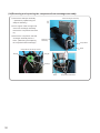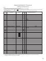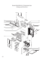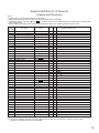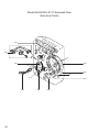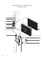
1
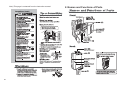
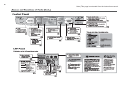
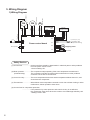
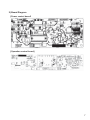
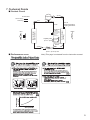
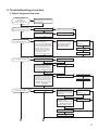
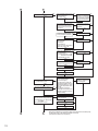
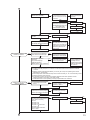
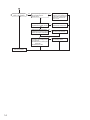
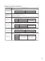
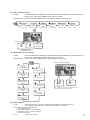
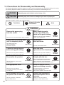
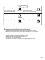
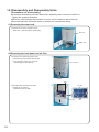
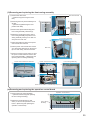
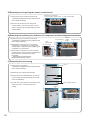
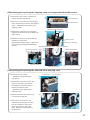
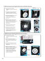
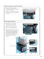
DEHUMIDIFIER SERVICE MANUAL Model 2013 No.MJW-E-1207A MJ-E21BG-S1-IT Sold from 2013 CONTENTS 1. 2. 3. 4. 5. 6. 7. 8. 9. 10. 11. 12. 13. 14. 15. Precautions Names and Functions of Parts Specifications Outer Dimensions Wiring Diagram Function Technical Points Precautions for failure diagnosis Troubleshooting Procedure Troubleshooting Maintenance Service Checklist Precautions for Disassembly and Reassembly Disassembly and Reassembly Hints Parts Catalog 2 3 5 5 6 8 9 10 11 18 19 21 22 24 32 2 1. Precautions Note) This page is extracted from the instruction manual. Note) This page is extracted from the instruction manual. 2. Names and Functions of Parts 3 4 Note) This page is extracted from the instruction manual. 3. Specifications Note) This page is extracted from the instruction manual. 4. Outer Dimensions 5 5. Wiring Diagram CM R FM SV P200 Sensors (Humidity and room temperature sensing) P201 Yellow/Green Red Red Orange Orange Blue Blue Operation control board Yellow Black Blue White Red Gray S Solenoid valve C Blower fan motor Compressor 1) Wiring Diagram P5 P2 P3 P100 P101 P10 1℃ (defrost)/12℃ (end) Blue Power plug Brown P1 Power control board P11 Gray Run capacitor P4 Thermistor (Tube temperature sensing) White White SM P20 Stepping motor Gray P13 Gray Float switch Gray Safety Devices (1) Current fuse ....................Overcurrent flow caused by deterioration in electrical parts or other problems turns the power source to OFF. <Current setting: 2A> (2) Motor protector................The compressor stops operating if the room temperature exceeds 35°C. (Overload relay) The compressor will also shut down when malfunctions or other problems cause the current flow to exceed 5.3A. (3) Control circuitry ...............The room temperature thermister senses temperature below about 0°C, and shuts down the compressor. (4) Thermal fuse ...................When blower motor temperature exceeds 133°C due to blower locking or other malfunctions, blower operation shuts down. (5) Current fuse for compressor protection ................... If the protection by motor protector and control circuitry is not effective, the compressor shuts down when the current to it exceeds approximately 10A. <Setting current: 10A> 6 2) Board Diagram [Power control board] [Operation control board] 7 6. Function ■ Function List Operation mode Compressor Blower fan Solenoid valve LED indicator Swing louvre Power Intelligent Lamps Air Purifier Full Drying inside Humidity (set/current) Operation mode HIGH LCD indicator Swing area Swing monitor Off/on timer Mildew guard Defrost Low temp Child lock Power Selection Mode Button Humidity Selection Air purfier Swing louvre Off/on timer Drying inside Child lock Note 8 : Display lamp/Operable : Timer - flashes when on : Off/stopped/inoperable : Operable only when swing on/lit : Operable only when swing on and blower fan rotates : LCD/LED lights at each operation mode : LCD/LED flashes at each operation mode : Lights at room temperatures of 14℃ or under : Varies by conditions. ON : ON LED lit or flashing OFF : OFF LED lit Child lock On timer counting On timer being set Off timer on Defrost Full Drying inside Air purifier Intelligent Laundry Easy dehumidifying Low Temp Mildew guard Low High Auto Operation off Dehumidifying operation 7. Technical Points ■ Coolant Circuit φ6.35 Compressor Coolant flow Dehumidifying Defrosting φ5 φ5 φ6.35 Tube temperature sensing thermistor Solenoid valve Fan (closed when dehumidifying and open when defrosting) Heat exchanger (heat radiation) Blow Capillary tube φ5.0×φ4.0 Humidity sensor Heat exchanger (cooling) φ6.35 Intake Room temperature sensing thermistor φ6.35 φ6.35 Capillary tube φ2.0×φ0.8×φ340 ■ Performance curve Note) This page is extracted from the instruction manual. 9 8. Precautions for failure diagnosis The following precautions should be observed in order to perform troubleshooting safely and correctly. The following diagrams indicate circumstances where danger can result from mishandling the unit. WARNING Mishandling may result in fatal or serious injury, or fire. CAUTION Mishandling may result in minor or damage to your home or property ,etc. Meanings of graphic symbols are explained below. Always follow the instructions Forbidden Alert WARNING Remove the power plug from the socket. Unplug When performing work with the power on, be careful not to touch the live part. Electric shock Failure to do so may cause electric shock or injuries. This may cause electric shock. Do not touch a rotating object until it completely stops. Do not work with wet hands. Don’t touch No wet hands The rotating object may catch your hand etc, and result in injuries. This may cause electric shock. Check the wiring diagram before wiring processing. After the work, lay the wire out as it was before. Check Return to as it was Failure to do so may cause combustion, generation of smoke, and/or malfunction. Failure to do so may cause combustion, generation of smoke, and/or malfunction. CAUTION 10 Wear protective gloves. Keep children away. Wear gloves Failure to do so may result in injuries by the edge of metal, electric shock, and/or burns caused by contact with hot section. Keep away Failure to do so may result in electric shock and/or injuries when moving the unit or using a measuring device. 9. Troubleshooting procedure 1) Failure diagnosis flowchart Are error codes displayed? “E0” “E1” “E7” “E8” “A1” “A2” “A3” “A6” “P4” NO Does the power lamp light by turning the power on? YES Refer to “Error Indications and CorrectiveActions,” and follow the procedures. NO Check the continuity of power cord. NG Replace the power cord. OK OK YES Check the current fuse of power control board (2A/250V). NG Replace the power control board. NG Check if there is no disconnection or contact failure of the connectors and connector pins of powercontrol board. OK OK Does the detective buzzer beep by turning the power on? NO Check if the lamps and LCD of control panel light. *How to put out all lighting(Press YES the mode switch and the humidity selection switch together 4 times when the power is off. Turn on the power within 2 seconds.) *Check if LED on the operation control board is down. (When LED is down, correct it.) NG NG Replace the operation control board. NG YES NO Is the tank filled with water ? NO OK YES NG Check the float. ,VWKHIORDWVZLWFKFRPLQJRII or attached upside-down? Is the float movement smooth? Is a magnet attached to the float? OK Check the float switch. Check if there is no disconnection or OK Replace the power control board. OK Is “Full lamp” lighting? Insert the connector OK and connector pins securely. NG Drain water from the tank. NG Check the float. NG Replace the float switch. NG contact failure of the connector (P13) and connector pins of power control board. Check the continuity between connecter (P13) terminals when the water tank is equipped. Normal… Tank full:open Empty:short Replace the power control board. NG OK Replace the operation control board. OK OK Does it dehumidify? NO Does the blower fan motor rotate? NO YES YES Check if there is no disconnection NG or contact failure of the connector (P2) and connector pins of power control board. OK Check the resistance of the NG blower fan motor. Normal:Between yelORZDQGEOXHȍ %HWZHHQEODFNDQGEOXHȍ Abnormal: Open or short OK Insert the connector and connector pins securely. NG OK OK Replace the blower fan motor. NG Replace the power control board. OK NG Replace the operation control board. OK A B 11 A B Does the compressor operate? NO YES Is the operating environment YES low temperature? (less than 2°C) NO Dehumidification may not be OK possible in low temperature environments. (The compressor does not operate by detecting abnormal low temperature) NG Check if there is no disconnection NG or contact failure of the connector (P5) and connector pins of power control board. Insert the connector OK and connector pins securely. NG OK Check the current fuse of NG motor protector (2A/250V). Replace the current fuse. OK NG OK Check the continuity of the NG motor protector. Nornal:Open Abnormal:Short * Check it at room temperature when the power is off. Replace the motor protector. OK NG OK NG Check the resistance of the compressor. Nornal:Terminal C-R 17ȍ 7HUPLQDO&6ȍ Abnormal:Open or short Replace the compressor. OK NG OK Is there an overcurrent? (The surface of the compressor is hot.) YES Replace the compressor. OK NG NO Replace the power control board. OK NG Replace the operation control board. OK Is the heat exchanger (evaporator) cold? NO YES Are the power consumption and current normal? NO YES NO Check the resistance of the tube temperature sensing thermistor. Nornal:%HWZHHQ3SLQVNȍ WRNȍ Abnormal:Open or short YES Check the coolant circuit. NG (If the coolant leaks. If the tube clogs.) ƔThe part of the cooler near the tube temperature sensor should be at least 10°C lower than room temperature when normal. ƔThe bottom of the heat exchanger has frost when the quantity of coolant is little by coolant leaking. Replace the parts that coolant is leaking or the tube is clogged. OK Replace the tube temperature OK sensing thermistor NG Replace the power control board. OK NG Replace the operation control board. OK C 12 D *Note: Do not replace the compressor easily excpet when the overcurrent(Lock), the abnormal noise or the abnormal vibration is occured. (includes the oil leak in the compressor) C D Does the solenoid valve operate? NO (Shorten J301 and J302) YES Check if there is no disconnection NG or contact failure of the connector (P3) and connector pins of power control board. Insert the connector and connector pins securely. NG OK NG Check the resistance of the solenoid valve coil.(P3 connector) Nornal:Between the pin1 and pin2 2.0kȍ-2.2kȍ Abnormal:Open or short Replace the solenoid valve coil. OK NG Replace the power control board. OK NG OK Replace the operation control board. OK Are there any clogs or dust on the filter. YES Clean filter. OK NG NO Is the operating environment low humidity and low temperature? YES It is normal. Dehumidication may not be possible in low humidity and OK low temperature environments. Explain the performance curve on P9. YES It is normal. Defrost mode is operating. Airflow stops in a few minutes. NO The unit is normal. The unit stop working in the middle of operation. YES Is the defrost mode selected? Does the defrost indicator light? NO NO Is automatic operation YES selected? Easy dehumidifying / Intelligent laundry / Mildew guard / Auto / Off timer Is the operating YES environment low humidity and low temperature? NO Dehumidication may not be possible in low humidity and low temperature environments. Explain the performance curve on P9. 1) Easy dehumidifying:It stops according to the humidity level. 2) Intelligent laundry:It stops in a minimum of about 60 minutes and a maximum of about 12 hours. 3) Mildew guard:It operates intermittently 2-4 hours (24 hours).The operating time varies depending on the humidity. 4) Auto:Compressor and blower fan stop when current humidity is -1% of set humidity or less. 5) Off timer:It stops at the set time. 6) All operation mode:Is the off timer operation selected with other operation mode? Off timer operation has priority over other modes. 1-6 indicate that the unit is operating normally. Explain that to the customer. Stepping motor (louvre) does not operate. NO YES Is the swing louvre switch “OFF”? YES NO Does the swing direction of YES the louvre change to “Wide”, “Upward”,or ”Rear”? The unit is normal. NO Check if there is no disconnection or NG contact failure of the connector (P20) and connector pins of power control board. OK Check the resistance between NG connector pins of the stepping motor (P20 connector). Normal: Terminal1-2 Terminal1-3 342-418ȍ Terminal1-4 Terminal1-5 Abnormal:Each interval is open or short Insert the connector and connector pins securely. OK Replace the stepping motor. OK NG Replace the power control board. OK NG Replace the operation control board. OK OK E 13 E Only a small quantity of water is dehumidified. NO YES Is the operating environment YES low humidity and low temperature? NO Is there any dust on the room YES temperature and humidity sensor? Dehumidication may not be OK possible in low humidity and low temperature environments. Explain the performance curve on P9. Remove the dust from the room OK temperature and humidity sensor. NO Check if there is no disconnection or NG contact failure of the connector (P10) and connector pins of power control board. Insert the connector and connector pins securely. OK OK Check the resistance of the room NG temperature and humidity sensor. (P10 connector) Normal:Between the pin3 and pin4 NȍNȍ Abnormal:Open or short OK The unit is normal. 14 Replace the room temperature and humidity sensor. OK 2) Simple Check Table for Main Parts Component name Tube temperature sensing thermistor Room temperature and humidity sensor board Testing procedure Detach the connector and measure the resistance using a multimeter (component temperature: 10℃ to 30℃). Normal Abnormal Between P11 pins: 8.0kΩ to 20.8kΩ Open or shorted Detach the connector and measure the resistance using a multimeter (component temperature: 10℃ to 30℃). Normal: 47 to 51kΩ (between P10 pins 3 and 4) Abnormal: Open or shorted With the connector detached, measure the resistance across the terminals using a multimeter (winding temperature: 10℃ to 30℃). Abnormal Normal Compressor C-R side 17Ω ~ 19Ω C-S side 32Ω ~ 36Ω Open or shorted Measure the resistance between terminals using a multimeter (winding temperature: 10℃ to 30℃). Abnormal Normal Blower fan motor Yellow-Blue 217Ω ~ 236Ω Black-Blue 219Ω ~ 237Ω Open or shorted Measure the resistance between terminals using a multimeter (component temperature: 10℃ to 30℃). Solenoid valve coil Normal Abnormal 2.0kΩ ~ 2.2kΩ Open or shorted Measure the resistance across terminals with a multimeter. (Part temperature: approx 25℃) Stepping motor Normal Abnormal 342Ω ~ 418Ω Open or shorted Terminals 1-2 Terminals 1-3 Terminals 1-4 Terminals 1-5 15 3) Error Indications and Corrective Actions Indication (Timer display) Error (failure) E0 P10 connector out of position Room temperature thermistor blowout E1 Room temperature thermistor short Room temperature and humidity sensor board failure E7 P11 connector out of position Tube temperature thermistor blowout E8 Tube temperature thermistor short Tube temperature sensor failure A1 Microprocessor failure RAM error A2 Frequency determination error (When power is on) A3 Frequency determination error (During operation) A6 Watchdog timer error Replace the main board. P4 Compressor Follow the “Does it dehumidify?” in the “Failure diagnosis flowchart” of P11. Corrective action Check the P10 connection. Check the room temperature and humidity sensor board. Check the P11 connection. Check the tube temperature thermistor. Replace the main board. Outlet/power check (Replace the main and power supply boards.) 4) Self-Test Program and Execution Procedure (1) Deactivating 3-minute restart prevent lock ① Start: Press the MODE and HUMIDITY SELECTION buttons together 3 times when the power is off. Press the POWER button within 2 seconds. ② Functions: ① Deactivates 3-minute restart prevention lock (immediate operation) ② Fan: Fix at rank 6 (max. airflow) ③ Activates compressor ④ Operating mode: Low Temp ⑤ Low temperature is indicated on LCD. ⑥ When E2PROM error is detected, FULL, DRYING INSIDE and AIR PURIFIER LEDs are lit. ③ To end: Turn power off. The solenoid valve functions for 3 seconds. 16 (2) LED, LCD and fan tests ① Start: Press the MODE and HUMIDITY SELECTION buttons simultaneously 4 times when the power is off. Press the POWER button within 2 seconds. ② Mode select: Use the OFF/ON TIMER button to change the diagnosis mode (0 - 5). LCD and LED all lit Room temperature indicator Current humidity Tube temperature indicator Determined frequency Current fan rank Examples Mode displayed For current humidity (all displays in decimal) (3) Operation/Error history mode ① Start: Press the MODE and HUMIDITY SELECTION buttons simultaneously 5 times when the power is off. Press the POWER button within 2 seconds. ② Mode select: Use the OFF/ON TIMER button to select indicator mode (0-F). Example: Latest error display Compressor malfunction detected P4 error Error history display 0: Latest error 7: Oldest error Tube temperature Thermistor short-circuit detected E8 error Watchdog error Tube temperature Thermistor open-circuit detected E7 error A6 error Frequency determination error at power ON A2 error Room temperature Thermistor short-circuit detected E1 error Latest error Display mode When “display mode” is 8 to F, the number of error generations is displayed in hexadecimal. Frequency error when fan operated Room temperature Thermistor open-circuit detected A3 error E0 error (4) Demo program ① Start: With the power OFF, hold down the MODE and HUMIDITY SELECTION buttons, and press the POWER button. The demo program starts in 3 seconds. ② Operations (all buttons are disabled): ① Fan: Fixed at rank 3 ② Compressor/solenoid valve: Stopped ③ LCD/LED: Lights in random sequence ④ Swing louvre: Wide ③ End: Remove power plug. 17 18 10. Troubleshooting Note) This page is extracted from the instruction manual. 11. Maintenance Note) This page is extracted from the instruction manual. 19 Note) This page is extracted from the instruction manual. 20 12. Service Checklist (1) Points to be checked after completing repairing After completing repairing, check the all items below to prevent re-repair. Check items Check Was the proper tool used? Are the parts on the parts catalog used? Verify that there is no problem in the lead wire (layout and connection) and/or clamp. Verify that there is no defect, such as lead wire caught in other parts, damage, and/or intermediate connection. At installation Verify that there is no defect, such as deteriorated or damaged power cord and/or intermediate connection. Verify that there is no slack and/or damage to power cord. Are the connectors and metal terminals inserted securely? Verify that there is no abnormal sound of the motor etc. If electrical parts are replaced, was the insulation performance checked? Verify that there is no insufficient inserting or gap in the fitting and/or calking sections. Is the cushioning attached without fail? Is the parts requires silicon coating surely coated with silicon? Are the all sorts of specified screws on the parts catalog used? Are the all sorts of packing, washers, etc. installed without fail? Are the waterproofing and rust prevention performed on the products which require those treatment? Installation conditions Is the unit installed at the flat place? Is the unit installed at the stable place? (The unit is not easy to fall down?) Is a firm ground selected for the installation place? (Be careful with a hollow floor, corrosion, etc.) Is there enough space around the unit? (Is there no wall, ceiling, curtains, etc. near the unit?) Verify that the unit is not installed where it is exposed to direct sunlight or near heat- generating devices. Verify that the unit is not installed in a special environment. (places where chemicals are used or there is a lot of dust.) Is the product which requires earthing correctly earthed? (Do not connect the earth wire to a water pipe or gas pipe.) Explanation after repair Operation check Is the installation criteria described in the instruction or installation manual fulfilled? Is the power on when you turn it on? Is the basic operation described in the instruction manual successfully performed? Verify that there is no problem in operation around the open and close part, rotation part, slide part, etc. Verify that no abnormal sound or smell is emitted. Is the power off when you turn it off. Explain the content of repair, check, and/or adjustment to the customer well. Tell the customer to read the instruction manual well to use this dehumidifier. Tell the customer not to disassemble the product. Explain to the customer if the installation place is not good or if there is more efficient way. 21 13. Precautions for Disassembly and Reassembly The following precautions should be observed in order to perform disassembly and reassembly safely and correctly. The following diagrams indicate circumstances where danger can result from mishandling the unit. WARNING Mishandling may result in fatal or serious injury, or fire. CAUTION Mishandling may result in minor or damage to your home or property etc. Meanings of graphic symbols are explained below. Always follow the instructions Forbidden Alert WARNING Remove the power plug from the socket. When replacing parts, use the specified parts listed on the parts catalog. Unplug Failure to do so may cause electric shock or injuries. Failure to do so may cause combustion, smoke, and/or malfunction, Do not touch a rotating object until it completely stops. Do not work with wet hands. The rotating object may catch your hand etc, and result in injuries. Don’t touch After the work, lay the wire out as it was before. Check Failure to do so may cause combustion, generation of smoke, and/or malfunction. Return to as it was Do not alter the product. Comply with the law. This may cause fire, electric shock, and/or injuries. Follow the applicable laws and regulations, such as “Fire Prevention Ordinance” and Obey the law “Electric Equipment Technical Standards.” Failure to do so may cause fire and electric shock. No alteration Use appropriate tools. Failure to do so may result in an accident caused by contact failure or loose parts. Earth the product which requires earthing correctly. Use proper tools Do not damage or process the power cord or lead wire. This may cause fire, combustion, and/or electric shock. 22 No wet hands This may cause electric shock. Check the wiring diagram before wiring processing. Failure to do so may cause combustion, generation of smoke, and/or malfunction. Return to as it was Incomplete earthing or connection to a gas pipe, water pipe, etc. may cause an explosion or electric shock. Earth Replace the damaged or deteriorated power cord or lead wire. Forbidden Failure to do so may cause fire, combustion, and/or electric shock. Replace CAUTION Wear protective gloves. Keep children away. Wear gloves Failure to do so may result in injuries by the edge of metal, electric shock, and/or burns caused by contact with hot section. Keep away Failure to do so may result in electric shock and/or injuries when moving the unit or using a measuring device. Do not put the unit where it may burn. Check the firmness of installation location. This may cause fire, or combustion. Do not install unit Perform operation check after reassembly. Failure to do so may result in an accident or malfunction. Check The product may fall down, which could cause an accident or injuries. Do not wash the unit with water. Operation check No water This may result in fire, combustion, or malfunction Safety precautions for the inspection and service 1. When the service requires disassembly, be sure to remove the power cord from the outlet. 2. When it is necessary to perform the work with the power on, be careful not to touch the live part. 3. Use appropriate tools for the work. 4. Use the specified parts listed on the “Parts Catalog” of the applicable model. 5. Check the deterioration of the power cord and lead wire at service. Replace the damaged or deteriorated power cord and lead wire. 6. After the service, perform the operation check. Verify that the tank full detection works properly and the unit operates without a problem. 23 14. Disassembly and Reassembly Hints 【Precautions for disassembly】 Ɣ&RQQHFWLRQVKRXOGEHSHUIRUPHGZLWKRXWIDLOHVSHFLDOO\ZKHQVFUHZVDUHXVHGIRULW 7LJKWHQWKHVFUHZVLQWKDWFDVH Ɣ:KHQWKHFDEOHWLHIL[LQJWKHOHDGZLUHLVFXWEHVXUHWRUHSODFHLWZLWKDQHZRQH Ɣ5HPRYHGOHDGZLUHVKRXOGEHIL[HGWRDFODPSHUHWFDQGSHUIRUPZLULQJ (1)Removing the water tank ①Open the front door and pull out the water tank.ĺ5HPRYLQJWKHZDWHUWDQN ① Main unit Water tank (2)Removing the front panel and air filter ①Push the front panel downward, and SXOOWRZDUG\RXWRUHOHDVHWKHFDWFKHV RQWKHERWWRP3XVKXSWRUHPRYH ĺ5HPRYLQJWKHIURQWSDQHO ① Front panel Catches Tabs ②Hold the tabs and pull the air filter WRZDUG\RXWRUHPRYH ĺ5HPRYLQJWKHDLUILOWHU ② Air filter Air filter 24 Tabs (3)Removing and replacing the front casing assembly ①Remove the water tank. ĺ (Reference:(1)Removing the water tank) Special setscrews ③ ②Removing the front panel assembly and air filter. ĺ5HIHUHQFH5HPRYLQJWKHIURQW panel and air filter) ④ ④ Catch(left side:1) Catch(Right side:1) ③5HPRYHWKHVSHFLDOVHWVFUHZVDQG front casing assembly setscrews(4). Front casing assembly setscrews ④'HWDFKWKHFDWFKHVIURPWKHVLGHRI front casing assembly and pull the front casing assembly toward you so that it is away from the main unit. Front casing assembly ④ ⑤Raise the handle and remove the power control board box setscrew. ⑥Pull the power control board box toward \RXGHWDFKWKHFDWFKHVRQWKHER[OLG (one on each side), and remove the lid. Main unit ⑦Remove connectors P100 and P101 from the power control board and remove the IURQWFDVLQJDVVHPEO\ĺ5HPRYLQJDQG replacing the front casing assembly) Power control board box setscrew Power control board box lid ⑤ Front casing assembly ⑥ ⑦ Catches ⑦ Handle Power control board Connectors(P100,P101) (4)Removing and replacing the operation control board ①Remove the front casing assembly. ĺ5HIHUHQFH5HPRYLQJDQGUHSODFLQJ the front casing assembly) ②Detach the catches(bottom:4,right side:1) to remove the operation control ERDUGĺ5HPRYLQJDQGUHSODFLQJWKH operation control board) Operation control board ② Front casing assembly Catch Catches 25 (5)Removing and replacing the power control board ①Remove the power control board box lid. ĺ5HIHUHQFH5HPRYLQJDQGUHSODFLQJWKH front casing assembly) Remove all connectors from the power control board Power control board ② ②Remove all connectors from the power control board to remove the power control ERDUGĺ5HPRYLQJDQGUHSODFLQJWKHSRZHU control board) (6)Removing and replacing the condenser for compressor and tube temperature thermister ①Remove the power control board box lid. ĺ5HIHUHQFH5HPRYLQJDQGUHSODFLQJWKH front casing assembly) ②Remove the connector P4 to remove the condenser for compressor from the power FRQWUROERDUGĺ5HPRYLQJDQGUHSODFLQJWKH condenser for compressor) ③Remove the connector P11 from the power control board to remove the tube temperature thermister from the right side of heat exchanger. ĺ5HPRYLQJDQGUHSODFLQJWKH temperature/humidity sensor) Connector(P4) ③ Tube temperature thermister Power control board Connector(P11) ② ③ Heat exchanger Condenser for compressor (7)Removing the rear casing ①Remove the front casing. ĺ5HIHUHQFH5HPRYLQJDQGUHSODFLQJWKH front casing assembly) Louvre ② ②Detach the rear casing setscrews(6). ③Detach the screw stop bosses(2) on the top of rear casing and the guides(2) on the side of the fan assembly. Rear casing setscrews ④Lift the rear casing upward, and remove from XQGHUWKHORXYUHĺUHPRYLQJWKHUHDU casing) Louvre ③ ④ ③ Catches (one on each side) Rear casing 26 (8)Removing and replacing the stepping motor and temperature/humidity sensor ①5HPRYHWKHUHDUFDVLQJĺ5HIHUHQFH (7)Removing the rear casing) ② ③ Connector(P10) ②Remove the connector P20 and stepping motor setscrews(2) to remove the stepping PRWRUĺ5HPRYLQJDQGUHSODFLQJWKH stepping motor) Connector(P20) Stepping motor setscrews ③Remove the connector P10 and tape to separate the lead wire from the blower fan guide casing. ② ④Detach the catch(1) from the blower fan Stepping motor assembly to remove the WHPSHUDWXUHKXPLGLW\VHQVRUĺ5HPRYLQJ Blower fan assembly and replacing the temperature/humidity sensor) Temperature/humidity sensor Blower fan assembly Blower fan assembly Catch ③ ④ Blower fan assembly ④ ④ Drainpan assembly Temperature/humidity sensor Drainpan assembly (9)Removing and replacing the solenoid valve and plug cord ①Remove the rear casing. ĺ5HIHUHQFH5HPRYLQJWKH rear casing) ②Remove the connector P3 from the power control board and remove the solenoid valve setscrew(1) to remove the solenoid valve. ĺ5HPRYLQJDQGUHSODFLQJWKH solenoid valve) ③Remove the earth wire setscrew(1) to remove the earth wire. ④Remove the connector P1 and separate the power plug cord wire from the clamper to remove the power plug from the gap of the EDVHĺ5HPRYLQJDQGUHSODFLQJ the plug cord) Connector(P1) Connector(P3) ② ④ Solenoid valve Solenoid valve setscrew ④ ③ Earth wire setscrew Earth wire Plug cord Gap Base 27 (10)Removing and replacing the blower fan and blower fan motor ①Removing the rear casing. ĺ5HIHUHQFH5HPRYLQJWKHUHDU casing) Blower fan Blower fan guide casing Blower fan locknut ③ Catch ③ ④ ②Remove the power control board. ĺ5HIHUHQFH5HPRYLQJDQG replacing the power control board) ③Remove the blower fan locknut(1) to remove the blower fan. ĺ5HPRYLQJDQGUHSODFLQJWKH blower fan) ④Detach the catch which fixes the blower fan motor lead wires to blower fan guide casing and detach lead wires from the blower fan guide casing. Blower fan motor Blower fan motor holding plate setscrews Blower fan motor ④ ⑤ Blower fan motor holding plate Cushion ⑥ Blower fan motor (blower fan side) ⑤Remove the blower fan motor holding plate setscrews(3). Cushion ⑥ ⑥Remove the blower fan motor holding plate and cushions to remove the blower fan motor. ĺ5HPRYLQJDQGUHSODFLQJWKH blower fan motor) Blower fan motor (casing side) Blower fan motor holding plate (11)Removing and replacing the blower fan assembly ①Removing the rear casing. ĺ5HIHUHQFH5HPRYLQJWKHUHDU casing) Heat exchanger assembly Drainpan assembly ④ ②Removing the power control ERDUGĺ5HIHUHQFH5HPRYLQJ and replacing the power control board) ③Remove the lead wires from the clampers on the blower fan guide casing sides. ④Detach the catches from the blower fan assembly and drainpan assembly.Then Pull upward the blower fan assembly leaning toward the heat exchanger to remove the blower fan assembly. ĺ5HPRYLQJDQGUHSODFLQJWKH blower fan assembly) Catches(2) ④ ④ Blower fan assembly Drainpan assembly 28 Blower fan assembly Catches(2) (12)Removing and replacing the float switch ①Remove the blower fan assembly. ĺ5HIHUHQFH5HPRYLQJDQGUHSODFLQJ WKHEORZHUIDQDVVHPEO\ Drainpan assembly Heat exchanger assembly ② ②Remove the float switch form the drainpan DVVHPEO\ĺ5HPRYLQJDQGUHSODFLQJWKH IORDWVZLWFK Float switch (13)Removing the drainpan ①Remove the blower fan assembly. ĺ5HIHUHQFH5HPRYLQJDQG UHSODFLQJWKHEORZHUIDQDVVHPEO\ ③ Rear side of the drainpan assembly ②Separate all the lead wires from the clampers on the drainpan assembly. ③'HWDFKWKHFDWFKHVRQWKHUHDUVLGH RIGUDLQSDQDVVHPEO\DQGFDWFKHVRQ the front side of drainpan assembly. Pull the base backward while lifting the right side of the heat exchanger and remove the drainpan assembly from the EDVHĺ5HPRYLQJWKHGUDLQSDQ DVVHPEO\ Catches Heat exchanger ③ ③ Front side of the drainpan assembly Base Catch Drainpan assembly ③ Base Compressor Front side of the drainpan assembly Catch Base 29 (14)Removing and replacing the compressor/heat exchanger assembly ①Remove the drainpan assembly. ĺ5HIHUHQFH5HPRYLQJWKH drainpan assembly) Heat exchanger assembly ② ③ ②Put a support under the right side RIWKHKHDWH[FKDQJHUDVVHPEO\ Remove the compressor setscrews ③Remove the compressor and heat H[FKDQJHUDVVHPEO\IURPWKH EDVHĺ5HPRYLQJDQGUHSODFLQJ the compressor/heat exchanger) Drainpan assembly Compressor Base <Compressor part:wiring layout> Red(S) Gray(R) White(C) Base 30 Compressor setscrews 31 15. Parts Catalog Model MJ-E21BG-S1-IT Exploded View <Casing and Structure> D 114 109 107 C B 108 106 113 105 112 111 117 110 A 116 115 102 32 103 101 104 118 Ins t Borouction k Model MJ-E21BG-S1-IT Parts List <Casing and Structure> Notes: 1. Circled reference numbers indicate performance parts. 2. New parts and the parts that are used only with these models lack compatibility. 3. Those parts that are marked by and are of critical importance for sustaining safety and performance. Use specified parts atreplacement. 4. When ordering parts without part numbers, use the design number. The order may take a while to process. Exploded View Matching No. Part Name 101 102 103 104 105 106 107 108 109 110 111 112 113 114 115 116 117 118 TANK*160VX COVER-T*ASSY-E16VX-W LID-TANK*160VX FLOAT*ASSY-100S(X) CASE-F*100VX-C ESC-SW*E21BG-S1-IT PCA*E21BG-S1-IT*M CLAER-PLATE*E16VX FIXTURE-PCA-M*100T(X) PANEL-F*ASSY-E16VX-W FILTER*ASSY-E82CF FILTER-MJPR-ECGFT CASE-R*160VX HANDLE*100/160V(X) BASE*EBG DRAINPAN*E22WX SWITCH-LEVEL*160WX TANK*ASSY-160VX A B C D SCW-PL-TBFZR 4X12 SCW-MPFZR M4X14-TORX SCW-PL-TBFZR 4X12 SCW-PL-TBFZR 4X16 Part No. M22 C89 345 M22 C39 741 M22 B29 697 M22 B25 379 M22 B25 233H M22 C96 440 M22 C96 689 M22 C62 449 M22 B19 781 M22 C39 001 M22 C84 320 M48 5C7 859 M22 C56 310R M22 B25 063 M22 C96 200 M22 C73 340 M22 C44 501 M22 C89 345T Safety Pc/1 Part unit 1 1 1 1 1 1 1 1 1 1 1 1 1 1 1 1 1 1 Compatibility/Miscellaneous E100BF-C E22VX 160VX 100VX 100VX New New E16AX-H 100T E22VX E82CF-H Expendable item E92CG-TW E22VX-C 100VX New E21CX-S1-IT E16VX-S1-IT E100BF-C 4 2 8 1 *1. If the part is out of production, you may be required to use a common part. *2. Parts found installed in products may have a different part number from service parts. However, there should be no difference inperformance and can be installed. 33 Model MJ-E21BG-S1-IT Exploded View <Casing and Structure> 209 213 212 211 206 207 205 216 214 210 218 A 208 220 204 219 Ins t Borouction k 201 217 215 34 202 203 221 Model MJ-E21BG-S1-IT Parts List <Casing and Structure> Notes: 1. Circled reference numbers indicate performance parts. 2. New parts and the parts that are used only with these models lack compatibility. 3. Those parts that are marked by and are of critical importance for sustaining safety and performance. Use specified parts atreplacement. 4. When ordering parts without part numbers, use the design number. The order may take a while to process. Exploded View Matching No. Part Name 201 202 203 204 205 206 207 208 209 210 211 212 213 214 215 216 217 218 219 220 221 - SPRING-S*100S(X) STOPPER-PLATE*100S(X) PACKING-RUB CASING-E22WX STEPPING-MOTOR*CX RUN CAPACITOR*E26RX LEAD WIRE-R/C*140TX BOX-PCA*S100D INS-PLATE-MICA*S100D COVER-BOX*S100D NET-100B LOUVER-V(X) SUPPORT-LOUVER*S(X) LEAD WIRE S/M*VX WHEEL*P(X) SUPPORT-HANDLE*160WX SHAFT-B*HX ESC-PL*E22VX ESC-FILTER*E22WX NAME-PL*E21BG-S1-IT I.B*E21BG-S1-IT P-CASE*E21BG-S1-IT A SCW-TPFZR 3X8N Part No. M22 B15 128 M22 B15 788 M22 J67 923 M22 C73 310 M22 B46 620S M22 C15 353 M22 B19 130 M22 C79 311 M22 B59 730 M22 C79 320 M22 B41 360 M22 B25 045 M22 B15 036 M22 J90 908 M22 C99 261 M22 B70 100 M22 C59 468 M22 C58 468F M22 C96 450 M22 C96 936 M22 C96 754 Safety Pc/1 Part unit 1 1 1 1 1 1 1 1 1 1 1 1 1 1 4 1 4 1 1 1 1 1 Compatibility/Miscellaneous 100SX 100SX 100NX E21CX-S1-IT H100CX E26RX-H 440V 8.0UF 100T E100WX-TW2 E100WX-TW1 E100WX-TW2 S100B 100VX 100SX 100P E20BG-E1 100HX E22WX-H-C E26WX-H New New New 2 *1. If the part is out of production, you may be required to use a common part. *2. Parts found installed in products may have a different part number from service parts. However, there should be no difference inperformance and can be installed. 35 Model MJ-E21BG-S1-IT Exploded View <Electrical Parts> 301 306 A 307 303 E C 302 B D 309 36 304 308 305 Model MJ-E21BG-S1-IT Parts List <Electrical Parts> Notes: 1. Circled reference numbers indicate performance parts. 2. New parts and the parts that are used only with these models lack compatibility. 3. Those parts that are marked by and are of critical importance for sustaining safety and performance. Use specified parts atreplacement. 4. When ordering parts without part numbers, use the design number. The order may take a while to process. Exploded View Matching No. Part Name 301 302 303 304 305 306 307 308 309 PBA-T*E14CG*P SENSOR*HUM-E22WX FAN-S100D*ASSY HOLDING PLATE-M*NX-R MOTOR-E22WX LEAD WIRE-C/P*EV(X) MOTOR PRO*ASSY-E22VX RUBBER-MOUNT*S(X) PLUG CORD*EVX-K/S1 M22 C92 689 M22 C73 150 M22 B25 500 M22 C98 260 M22 C73 620 NUT-LFZR M6 SCW-PL-TBFZR 4X12 SCW-TPFZR 5X35M SPL WASHER-R SCW-BPBN M4X6 M22 C60 041 A B C D E Part No. M22 C59 502 M22 B13 511 M22 C60 509 Safety Pc/1 Part unit 1 1 1 1 1 1 1 3 1 Compatibility/Miscellaneous E14CG-S1-SWE E21CX-S1-IT 100VX E14EG-E1 E21CX-S1-IT Lead wire attached E22WX-H 180SX E100VX-K 1 3 3 3 1 *1. If the part is out of production, you may be required to use a common part. *2. Parts found installed in products may have a different part number from service parts. However, there should be no difference inperformance and can be installed. 37 Model MJ-E21BG-S1-IT Exploded View <Compressor Parts> 419 411 412 A 401 403 402 413 414 415 416 406 417 418 404 421 405 407 408 409 420 38 422 410 Model MJ-E21BG-S1-IT Parts List <Compressor Parts> Notes: 1. Circled reference numbers indicate performance parts. 2. New parts and the parts that are used only with these models lack compatibility. 3. Those parts that are marked by and are of critical importance for sustaining safety and performance. Use specified parts atreplacement. 4. When ordering parts without part numbers, use the design number. The order may take a while to process. Exploded View Matching No. Part Name 401 402 403 404 405 406 407 408 409 410 411 412 413 414 415 416 417 418 419 420 421 422 S/COIL TAPE*ASSY-EDX SOLENOID VALVE-R TAPE THERMISTOR-EVA*CG COOLER*E22WX CONDENSER*E22WX CLIP*1400PX COVER TERMINAL*1400 PACKING*1400PX COMP*6TD068DCA41 PIPE-SV-CT*E22WX PIPE-CT*E100DX CHARGE-PIPE*CG JOINT-E16V(X) PIPE-DJ*EBG PIPE-IN-COOL*EBG PIPE-OUT-COOL*EBG PIPE-OUT-CON*E22WX PIPE-IN-CON*EBG PIPE COVER*COMP PIPE-SUC*E100DX*ASSY PIPE-DIS*E100DX*ASSY A SCREW SEMS M5X0.8X6 Part No. M22 C78 629 M22 C84 629 M22 C91 555 M22 C77 390 M22 C77 390H M22 B60 069 M22 J93 018 M22 J93 923 M22 C77 118 M22 C91 420 M22 C92 320 M22 C88 420S M22 C96 420 Safety Pc/1 Part unit 1 1 1 1 1 1 1 1 1 1 1 1 1 1 1 1 1 1 1 1 1 1 Compatibility/Miscellaneous 220-240V E140DX-H E82CF-H E92CG-TW E100DX-H E100DX-H E180VX-TW1 160PX 160PX 6TD068DCA41 E100DX-H E92CG-TW E14CG-S1-SWE E80CF-C New Damper attached 1 *1. If the part is out of production, you may be required to use a common part. *2. Parts found installed in products may have a different part number from service parts. However, there should be no difference inperformance and can be installed. 39