1
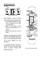
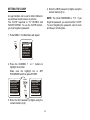
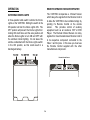
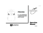
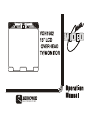
ON OFF
VOLUME
TV/AV
AUTO
MENU
CHANNEL
ENTER
®
ELECTRONICS CORP .
0
Congratulations on your purchase of the
Audiovox VOH1502 drop down TV/Video
Monitor. The VOH1502 has been designed to
give you and your family many years of video
entertainment in the mobile environment. Please
read the directions that follow to familiarize
yourself with the product and to ensure that you
obtain the best results from your equipment.
NOTE: Installation options vary. See the
individual Owner’s Manuals for each component
in your system to obtain a full understanding of
each component’s operation.
IMPORTANT NOTICE
An LCD panel and/or video monitor may be
installed in a motor vehicle and visible to the
driver if the LCD panel or video monitor is used
for vehicle information, system control, rear or
side observation or navigation. If the LCD panel
or video monitor is used for television reception,
video or DVD play, the LCD panel or video
monitor must be installed so that these features
will only function then the vehicle is in ‘park’ or
when the vehicle’s parking brake is applied.
SAFETY PRECAUTION
WARNINGS
v Do not use any solvents or cleaning materials
when cleaning the video system.
v Do not use any abrasive cleaners, they may
scratch the screen.
Use only a lightly
dampened lint free cloth to wipe the screen if
it is dirty.
v Lock the LCD screen in the fully closed
position when not in use.
v Before putting on headphones always adjust
the volume setting to the lowest position.
v Remember to leave the dome light switch in
the off or auto positions when the vehicle is
unattended, as the dome lights, if left on, can
drain the vehicle’s battery.
v Do not put pressure on the screen.
v Do not allow children to touch or scratch the
screen, as it may become dirty or damaged.
For safety reasons, when changing Video Media
it is recommended that the vehicle is not in
motion, and that you do not allow children to
unfasten seat belts to change Video Media or
make adjustments to the system.
System
adjustments can be accomplished using the
Remote Control while seat belts remain fastened.
Enjoy your Audiovox entertainment system but
remember safety of all passengers remains the
number one priority.
1
TELEVISION RECEPTION
FEATURES
This entertainment system is designed primarily
for viewing pre-recorded movies or playing video
games. Television reception in a moving vehicle
will be limited and in some areas will not be
possible due to weak and variable signal
strength. Television viewing in a stationary
vehicle will result in an improvement, but may still
be marginal due to signal strength. The quality
of the picture will not be consistent with home TV
reception. Reception may be affected by the
weather and distance from the TV station. A
weak signal may cause the picture to roll, be
snowy, or cause some color loss.
• 15” TFT (Thin Film Transistor) Active Matrix
LCD (Liquid Crystal Display) Monitor
• OSD (On Screen Display) For Control Of
Picture Quality And Functions
• Full Function Remote Control
• Television Tuner
• Remote Sensor Eye
• Four Audio / Video Source Inputs
• Speaker Amplifier
• Back-Lit Controls For Low Light Operation
• Dual Channel Infrared Wireless Headphone
Transmitter
• Dual Dome Lights
• Jack for Optional 49 Mhz RF Transmitter (for
Wireless 49 Mhz RF Headphones)
2
FRONT PANEL CONTROLS
1.
2.
3.
4.
POWER
VOLUME p/q
TV/AV
INFRARED RECIEVER AND
INFRARED TRANSMITTER
5. THREE POSITION DOME LIGHT
SWITCH
6. SCREEN RELEASE
7. MENU
8. CHANNEL p/q
9. ENTER
10. DOME LIGHT
Figure 1. FRONT PANEL CONTROLS
3
6. Screen Release *– Slides in the direction
of the arrow to release the drop down
screen.
FRONT PANEL CONTROLS
(See Figure 1)
1. Power Button – Turns the Monitor ON and
OFF.
7. Menu Button – Press the MENU button,
The MENU display appears. Use the
channel p and q buttons to highlight the
desired function, then press the ENTER
button to confirm your selection.
2. Volume p/q – Controls the volume of the
external Speakers or wired Headphone
jacks if connected. Also, used to adjust the
picture control setting when “contrast”,
“bright”, “sharpness”, “color” or “tint” is
displayed on the screen.
8. Channel p/q – Changes the TV channel
(Also used to scroll Up/Down through the
menu options).
3. TV/AV – Each time the button is pressed
the Audio/Video source will change in the
following sequence TV, AV1, AV2 and
AUX.
9. ENTER Button – Use this button to
confirm your selection from the menu
options.
4. Sensor Eye – Allows the remote control to
operate the VOH1502’s OSD system (On
Screen Display). Also used to control A/V
accessories that are connected to the
VOH1502 using the accessory cable
(P/N 8010703).
10. Dome Lights – Provide additional interior
illumination.
5. Three Position Dome Light Switch
• Auto – Automatically switches on the
dome lights in conjunction with the
vehicle’s interior illumination.
• Off – The Dome lights will not turn on in
this position.
• On – Turns on the Dome lights.
*Due to the size and weight of the LCD display, it
is recommended that you support the screen with
one hand while releasing it from the closed
position with the other hand.
4
BATTERY INSTALLATION
(See Figure 2)
6
TV POWER
TV/VIDEO
MUTE
7
1
Figure 2. BATTERY INSTALLATION
Before attempting to operate the Remote
Control, install the batteries as described below.
1) Turn the Remote Control face down. Press
down on the ridged area of the battery
cover, and slide it off.
2) Install Two “AAA” batteries as shown.
Make sure that proper polarity (+ or -) is
observed.
3) Slide the cover back until it clicks into
position.
2
ERASE/
ADD
8
1
2
3
4
5
6
7
8
9
AUTO
PROGRAM
9
0
1-
PICTURE
SELECT
ENTER
10
11
CH σ
3
VOL. –
VOL . +
4
CH τ
12
13
The Remote Control will operate the AUDIOVOX
VOH1502 as well as AUDIOVOX Televisions and
VCP’s. It is not a universal remote control and
will not control equipment from other
manufacturers.
15
If a universal Remote Control is used with the
VOH1502, choose the remote control encoding
scheme for Audiovox Televisions when
programming the remote.
5
VCP POWER
REW
F.FWD
REPLAY
PLAY
14
STOP
16
17
Figure 3. REMOTE CONTROL OPERATION
5
NOTE: These buttons will not affect the
volume of wireless headphones or a wired
RF modulator. When using these devices
the volume must be adjusted with the
headphone volume control or with your
radio’s volume control.
REMOTE CONTROL OPERATION
(See Figure 3)
Monitor Controls:
1. TV POWER
Press this button to turn on the VOH1502.
Press the button again to turn the set off.
5. MENU Button
Press the MENU button.
The MENU
display appears. Use the channel p and
q buttons to highlight the desired function,
then press the ENTER button to confirm
your selection.
2. Direct Access (0-9,1--) Number Buttons
Use these buttons to select a channel. The
channel number chosen will be displayed
on the screen for about four seconds. To
select channels 0-99, press two number
buttons. For example, to select channel 8,
press 0,8. To select channels above 100,
press the 1—button, then the number
buttons for the last two digits of the
channel. For example, to select channel
115, press 1--, 1, 5.
6. TV/VIDEO Button
Press this button to access the
AUDIO/VIDEO inputs. As the button is
pressed, the on screen display will cycle as
follows:
3. CHANNEL p/q Buttons
Use these buttons to advance to the next
higher (p) or lower (q) channel. (Also
used to scroll Up/Down through the menu
options).
TV
AV 1
AV 2
AUX
7. MUTE Button
Press this button to turn the TV sound off.
Press the button again to restore the sound
to the previously set level. MUTE may also
be released by pressing the VOLUME +/–.
4. VOLUME + / – Buttons
Use these buttons to raise or lower the
volume level of the Wired Headphones or
External Speakers if installed. They are
also used to make adjustments in the
picture select mode.
8. ERASE/ADD Button
When tuned to a channel press this button
to store or erase the channel from memory.
6
The stored channel numbers are displayed
in GREEN on the screen and the erased
channel numbers are displayed in RED.
NOTE: This function is also available in the
menu options under “Auto-Program”
automatically turn off if adjustments are not
made within five seconds.
9. AUTO PROGRAM Button
Select the correct antenna input (see page
12, Setting the “Antenna Input”) Press the
AUTO PROGRAM button.
All of the
channel numbers for TV or CABLE TV will
be scanned. The active channels will be
detected and automatically stored in
memory.
NOTE: This function is also available in the
menu options under “Auto-Program”
10. ENTER Button
Use this button to confirm your selection
from the menu.
11. PICTURE SELECT Button
Each time this button is pressed the onscreen picture adjustment display cycles
through “adjustment screens” as follows:
BRIGHTNESS
CONTRAST
COLOR
SHARPNESS
TINT
Then use the VOLUME +/- buttons to raise
(+) or lower (-) the level. The display will
7
5. STOP Button
Press this button to stop the videotape.
VCP CONTROLS
1. VCP POWER Button
This button is used to turn an optional
AUDIOVOX VCP ON and OFF.
6. REPLAY Button
Press this button will rewind the videotape
and immediately begin playback when the
videotape is fully rewind.
2. ”REW” REWIND Button
If this button is pushed while the tape is
stopped, the tape will rewind. If this button
is pushed while the tape is playing, the VCP
will go into rewind search mode. For more
information on search feature of the VCP,
consult VCP owner’s manual.
3. PLAY Button
Press this button to activate play mode
while a tape is loaded into the VCP. This
button may also be used to disengage
search and pause modes.
For more
information, consult the VCP owner’s
manual.
4. ”F.FWD” FAST FORWARD Button
If this button is pushed while the tape is
stopped, tape will fast forward. If this
button is pushed while the tape is playing,
the VCP will go into fast forward search
mode. For more information on search
feature of the VCP, consult the VCP
owner’s manual.
8
ADJUSTING THE PICTURE
CHANNEL
PICTURE
COLOR
CONTRAST
BRIGHTNESS
SHARPNESS
TINT
RESET
When watching TV programs, the quality of the
picture can be adjusted to suit your taste.
1. Press MENU. The main menu appears.
MENU
MAIN MENU
SELECT VIDEO
CLOSED CAPTION
SET PICTURE
AUTO-PROGRAM
ANTENNA INPUT
V-CHIP PROTECT
SET PASSWORD
32 BRIGHTNESS
ENTER
–
+
4. Adjusting the level:
Press VOLUME – to decrease the brightness.
Press VOLUME + to increase the brightness.
VOLUME
–
+
2. Press either CHANNEL p or q to highlight
the function.
50 BRIGHTNESS
CHANNEL
MAIN MENU
SELECT VIDEO
CLOSED CAPTION
SET PICTURE
AUTO-PROGRAM
ANTENNA INPUT
V-CHIP PROTECT
SET PASSWORD
ENTER
–
PICTURE
COLOR
CONTRAST
BRIGHTNESS
SHARPNESS
TINT
RESET
5. To adjust other items, repeat all above.
Note: The menu display disappears from the
screen if you do not press + or – within a few
seconds.
Whenever a menu or display disappears from
the screen, the + and – buttons return to the
volume adjustment buttons.
If you only want to adjust the picture, you can
use the remote control, simply press the
PICTURE SELECT.
Make sure the highlight bar is on SET
PICTURE and then press ENTER
3. Select the item to adjust. For example:
To adjust brightness, press CHANNEL p or
q to highlight BRIGHTNESS and press
ENTER.
9
SET PICTURE
AUTO-PROGRAM
+
Description Of Adjustment Items:
ITEM
Adjustment
Press VOLUME - to
CONTRAST
Press VOLUME + to
Decrease picture contrast for Increase picture contrast for
soft color
vivid color
BRIGHTNESS Darken the picture
Brighten the picture
SHARPNESS Decrease picture sharpness Increase picture sharpness
TINT
Make skin tones becomes Mark skin
Reddish
Greenish
COLOR
Decrease color intensity
tones
becomes
Increase color intensity
To Restore the Factory Settings
Select picture while the main menu is displayed.
Then highlight “RESET” and Press ENTER.
All the picture functions (BRIGHTNESS,
CONTRAST, COLOR, SHARPNESS, TINT) will
go back to the factory settings.
10
2. Press either CHANNEL p or q to highlight
the function.
Make sure the highlight bar is on CLOSED
CAPTION and then press ENTER.
SETTING CLOSED CAPTIONING
CLOSED CAPTIONING
Closed captioning lets you display the audio
portion of a program as text on the TV screen.
This is useful to the hearing impaired or anyone
who wants to watch a program without the
sound. There are two types of closed captioning
available: C1 (Caption 1) and C2 (Caption 2). C1
displays the full translation of the primary
language in your area. C2 may be used as a
source for secondary languages, simplified
English, or other translations transmitted in your
area. Closed captioning is not available on all
channels or at all times. Only specific programs
are encoded with closed captioning information.
CHANNEL
MAIN MENU
SELECT VIDEO
CLOSED CAPTION
SET PICTURE
AUTO-PROGRAM
ANTENNA INPUT
V-CHIP PROTECT
SET PASSWORD
3. Press the CHANNEL p or q buttons to
highlight the item and then press ENTER.
1. Press MENU. The Main Menu will appear
MENU
ENTER
CAPTION
CAPTION 1
CAPTION 2
OFF
MAIN MENU
SELECT VIDEO
CLOSED CAPTION
SET PICTURE
AUTO-PROGRAM
ANTENNA INPUT
V-CHIP PROTECT
SET PASSWORD
11
CABLE TV (CATV) OPERATION
AUTO PROGRAM FUNCTION
In addition to normal broadcast reception of VHF
and UHF channels, if you are a cable TV
subscriber, your new TV is capable of receiving
many unscrambled cable channels without the
use of a converter box.
1. Press the MENU button. The Main Menu will
appear on the screen.
2. Press the channel p or q buttons to highlight
AUTO PROGRAM and press ENTER. The
Program Menu will appear on the screen.
3. Press the channel p or q buttons to highlight
AUTO PROGRAM and press ENTER.
When set to broadcast TV it receives channels
2~69. When set to the CATV mode (STD) it
receives channels 1 ~ 125 (see chart).
SETTING THE “ANTENNA INPUT”
1. Press the MENU button. The Main Menu will
appear on the screen.
2. Press the channel p or q buttons to highlight
ANTENNA INPUT and press ENTER. The
Antenna Menu will appear on the screen.
3. Press the channel p or q buttons to highlight
either Air or Standard and press ENTER.
ENTER
Channels
Off Air
Cable
-
1
VHF (Channels 2 ~ 13)*
12*
12*
UHF (Channels 14 ~ 69)*
56
-
Low Midband A-5 ~ A-1 (Channels 95 ~ 99)
-
5
Midband (Channels 14 ~ 22 or A ~ I)
-
9
Superband (Channels 23 ~ 36 or J ~ W)
-
14
Ultraband (37 ~ 94 and 100 ~ 125 or w+29 ~ w+48)
-
84
68
125
Low VHF (Channel 01)
ENTER
Total*
12
4. Enter the NEW password (4 digits) using the
numeric buttons (0-9).
SETTING THE V-CHIP
An age limitation can be set to forbid children to
see and hear violent scenes or pictures.
The V-CHIP responds to “TV RATING” and
“MOVIE RATING”. To use the V-CHIP function,
you must register a password.
NOTE: The initial PASSWORD is 1111. If you
forget the password, you cannot set the V-CHIP.
To avoid forgetting the password, write it down
and Keep in a Safe place.
1. Press MENU. The Main Menu will appear
MENU
MAIN MENU
SELECT VIDEO
CLOSED CAPTION
SET PICTURE
AUTO-PROGRAM
ANTENNA INPUT
V-CHIP PROTECT
SET PASSWORD
2. Press the CHANNEL ? or ? buttons to
highlight the function
Make sure the highlight bar is SET
PASSWORD and then press ENTER.
MAIN MENU
SELECT VIDEO
CLOSED CAPTION
SET PICTURE
AUTO-PROGRAM
ANTENNA INPUT
V-CHIP PROTECT
SET PASSWORD
CHANNEL
ENTER
PASSWORD
SELECT VIDEO
CLOSED CAPTION
SET PICTURE
AUTO-PROGRAM
ANTENNA INPUT
V-CHIP PROTECT
OLD PASSWORD
3. Enter the OLD password (4 digits) using the
numeric buttons (0-9).
13
5. Press either VOLUME + or VOLUME – to
adjust the control level of the desired setting.
TO SET THE V-CHIP
1. Press MENU. The Main Menu will appear.
6. TV RATINGS CHART:
MENU
MAIN MENU
SELECT VIDEO
CLOSED CAPTION
SET PICTURE
AUTO-PROGRAM
ANTENNA INPUT
V-CHIP PROTECT
SET PASSWORD
• TV Y: ALL children
• TV Y7: 7 years old and above
• TV G: General Audience
2. Press the CHANNEL ? or ? buttons to
highlight the function.
Make sure the highlight bar is V-CHIP
PROTECT and then press ENTER.
• TV PG: Parental guidance
• TV 14: 14 years old and above
• TV MA: 17 years old and above
3. Enter the password (4 digits) using the
numeric buttons (0-9).
NOTE: The initial password is 1111.
MAIN MENU
SELECT VIDEO
CLOSED
SET PICTURE
AUTO-PROGRAM
ANTENNA INPUT
V-CHIP PROTECT
SET PASSWORD
TV–Y
CHANNEL
None All
TV–Y7 None All FV
PASSWORD_ _ _ _
V-CHIP
ENTER
ON
TV–G
OFF
TV CHANNEL BLOCKING
MOVIE BLOCKING
4. In the V-CHIP PROTECT menu. Press either
CHANNEL ? or ? buttons to highlight the
function.
14
None All
TV–PG None All
D
L
S
V DL DS DV LS LV SV DLS DLV DSV LSV DLSV
TV–14 None All
D
L
S
V DL DS DV LS LV SV DLS DLV DSV LSV DLSV
TV–MA None All
L
S
V LS LV SV LSV
OFF
MP G
MP PG
MP PG-13
MP R
MOVIE RATING is not set
ALL ages
Parental guidance
Parental guidance, less than 13 years old
Under 17 years old, Parental guidance
suggested
MP NC-17 17 years old and above
MP X
Adult only
MP N/R Movie has not been rated or ratings do not
apply
When you select TV-Y7, TV-PG, TV-14 or TVMA, press either CHANNEL ? or ? buttons to
select the contained rating.
•
•
•
•
V/FV-VIOLENCE
S – SITUATIONS.
L – LANGUAGE
D – DIALOG
Press VOLUME + or – to adjust contained rating.
NOTE: The V-CHIP function is activated only on
programs and tapes that are encoded with a
rating signal.
Press VOLUME + or – to select the contained
rating (Block or Show).
7. MOVIE RATINGS CHART:
15
OPERATION
REMOTE INFRARED SENSOR/REPEATER
OVERHEAD DOME LIGHTS
The VOH1502 incorporates a Infrared Sensor
which relays the signals from the Remote Control
to allow the VOH1502 to be controlled simply by
pointing it’s Remote Control at the remote
sensor.
This provides control of auxiliary
equipment such as an Audiovox VCP or DVD
Player. The Remote Infrared Sensor can relay
signals from most manufacturers Remote Control
to its respective component connected to the
Video 1 and 2 inputs. In this case you must use
the Remote Control supplied with the other
manufacturers component.
A three-position slide switch controls the Dome
Lights on the VOH1502. Sliding the switch to the
ON position will turn the Dome Lights ON. The
OFF position will prevent the Dome Lights from
turning ON at all times and the auto position will
allow the Dome Lights to turn ON and OFF with
the vehicle’s interior lighting. Do not leave the
vehicle unattended with the Dome Lights switch
in the ON position, as this could result in a
discharged battery.
Remote Infrared Sensor
16
VIDEO OUTPUT
AUX IN-L (WHT)
AUX IN-R (RED)
AUX IN-V (YLW)
The VOH1502 provides a video output for an
optional Video monitor(s). This output will provide
a video signal that duplicates the signal
displayed by the VOH1502 to an additional
Monitor or Video display. Please see your
installer for more information.
IR2-IN-R (RED)
IR2-IN-L (WHT)
AUXILIARY A/V STEREO INPUTS JACK
The VOH1502 is equipped with an auxiliary A/V
input connector. The inputs are provided to
facilitate the connection of Audio/Video
equipment, such as a camcorder or video game
system. To play a source with these inputs, an
RCA patch cord is required to connect the
Audio/Video signals to their respective jacks.
Mono audio sources will require the use of an
RCA Y-cable (P/N 0892165) to connect to both
right and left inputs.
2-CHANNEL IR TRANSMITTER
The VOH1502 is equipped with a dual channel
IR transmitter for use with AUDIOVOX 2-Channel
Headphones (P/N IR2CHS).
• The “A” channel will transmit the audio from
the A/V source selected on the VOH1502.
• The “B” channel will transmit any audio
source such as a CD Changer or Satellite
Radio system connected to the IR2 inputs.
17
OPTIONAL ACCESSORIES
WIRED FM MODULATOR (P/N FMM100)
WIRELESS HEADPHONES
Your video system may be equipped with an
optional RF modulator, that allows you to listen to
the VOH1502’s audio signal by tuning your
vehicle’s radio to the selected frequency, (88.7 or
89.1- check with your installer) and turning on the
remote mounted RF modulator switch. (In most
cases this toggle switch will be located
underneath the driver’s side of the dash, check
with your installer for the exact location.)
Whenever the RF Modulator is ON, broadcast
radio reception will be poor. Turning the remote
mounted toggle switch OFF will allow for normal
radio reception.
The VOH1502 includes a built in Infrared
Transmitter for use with Audiovox Wireless
Headphones (P/N MVIRHS).
Turning the
Headphone switch ON will activate the internal
IR Receiver, the volume can then be adjusted
using the controls on each headset. Any number
of wireless headphones can be used, but all
must be within a line of sight from the transmitter,
as infrared transmissions, like visible light travel
only in a straight line.
NOTE: AUDIOVOX Wireless Headphones (P/N
MVIRHS) are for use with the “A” channel only.
If both A and B channels are used, AUDIOVOX
Headphones (P/N IR2CHS) will be required.
The VOH1502 has a Jack labeled “to FM
Transmitter”, this Jack is for connection of an
optional Audiovox RF Transmitter (P/N
WTXRF01). This Transmitter is for use with the
Audiovox Wireless RF Headphones (P/N
WHPRF01).
Consult the documentation accompanying the
Audiovox Wireless Headphones for more
information.
18
11
LI N E OU T-L
TW O D OM E
LI G H T’S
C ON NE C TI ON
Lamp Auto
Purple/Brown
Constant 12V
Black/Red
Lamp On
Red/Black
Positive Dome Light Switching
SP EA KE R O R
H EAD P HO N E
C ON NE CT I ON
Lamp Auto
18
TO
F M T R AN SMI TT ER
7
8
9
LI NE O U T-R
12
L I NE O UT -V
6
10
14
13
17
16
15
Negative Dome Light Switching
P O WER (+1 2V)
3
4
5
P OWE R(G N D)
1
2
Purple/Brown
Ground
Black/Red
12Vdc
Red/Black
PIN 1 – Power -Red
PIN 2 – Power GND -Black
Antenna
PIN 3 – Dome Light Auto -Purple/Brown
PIN 4 – Lamp Common -Black/Red
PIN 5 – Dome Light On -Red/Black
PIN 6 – Line Out (L) -White
PIN 7 – Spk Out (R) -Green
PIN 8 – Spk Out GND -Black
PIN 9 – Spk Out (L) -Grey
PIN 10 – Video Out -Yellow
PIN 11 – Video GND -Black
PIN 12 – Line Out (R) -Red
Accessory
Harness
PIN 13 – Power 12V(FM Trans.) -Red
PIN 14 – Power GND (FM Trans.) -Black
IR Transmitter LED
PIN 15 – Audio (L) Out (FM Trans.) -White
2 PIN IR
Connector
4 PIN
Power
Connector
19
PIN 16 – Audio GND (FM Trans.) -Black
Yellow RCA(Video)
PIN 17 – Audio (R) Out (FM Trans.) -Red
White RCA(Audio Left)
PIN 18 – Line Out GND -Black
Red RCA(Audio Right)
TYPICAL SYSTEM CONNECTIONS
Troubleshooting
PROBLEM
Poor TV Reception
SOLUTION
•
•
•
Poor radio reception (FM
modulator installed)
•
•
•
IR sensor inoperative
Specifications
•
•
•
Perform auto programming of
the tuner
Verify antenna condition.
NOTE: Due to the nature of TV
signals,
vehicle
motion,
direction the vehicle is facing,
distance from the transmitter,
nearby
surroundings
and
weather may adversely affect
TV
reception.
These
conditions may result in the
following: picture roll, “snowy”
picture, or momentary loss of
color. Please refer to page 2
for more information on TV
reception.
Check the condition of the
vehicle’s radio antenna.
Verify that the antenna is fully
raised
If a wired RF modulator has
been installed, verify that it’s
switch is turned to the off
position
Verify that the batteries in the
remote are fresh
Verify that the remote eye is
not obstructed.
Verify
that
the
infrared
transmitter is affixed over the
sensor eye of the component
to be controlled
20
LCD Brightness
260 nits (min)
Resolution XGA
1024x768
Operation Temperature
-10 ~ 65º C
Storage Temperature
- 40 ~ 85º C
Video Display System
NTSC
Audio Output
1W @ 16O
Current Draw
3.2A
Weight
6 KG
Overall Dimensions
63x392x370 mm
(H x W x D)
12 MONTH LIMITED WARRANTY
Applies to Audiovox Mobile Video Products
AUDIOVOX ELECTRONICS CORP. (the Company) warrants to the original retail purchaser of this product that should this product or
any part thereof, under normal use and conditions, be proven defective in material or workmanship within 12 months from the date of
original purchase, such defect(s) will be repaired or replaced with reconditioned product (at the Company's option) without charge for
parts and repair labor.
To obtain repair or replacement within the terms of this Warranty, the product is to be delivered with proof of warranty coverage (e.g.
dated bill of sale), specification of defect(s), transportation prepaid, to the Company at the address shown below.
This Warranty does not extend to the elimination of externally generated static or noise, to correction of antenna problems, to costs
incurred for installation, removal or reinstallation of the product, or to damage to tapes, discs, speakers, accessories, or vehicle
electrical systems.
This Warranty does not apply to any product or part thereof which, in the opinion of the Company, has suffered or been damaged
through alteration, improper installation, mishandling, misuse, neglect, accident, or by removal or defacement of the factory serial
number/bar code label(s). THE EXTENT OF THE COMPANY'S LIABILITY UNDER THIS WARRANTY IS LIMITED TO THE
REPAIR OR REPLACEMENT PROVIDED ABOVE AND, IN NO EVENT, SHALL THE COMPANY'S LIABILITY EXCEED THE
PURCHASE PRICE PAID BY PURCHASER FOR THE PRODUCT.
This Warranty is in lieu of all other express warranties or liabilities. ANY IMPLIED WARRANTIES, INCLUDING ANY IMPLIED
WARRANTY OF MERCHANTABILITY, SHALL BE LIMITED TO THE DURATION OF THIS WRITTEN WARRANTY. ANY ACTION
FOR BREACH OF ANY WARRANTY HEREUNDER INCLUDING ANY IMPLIED WARRANTY OF MERCHANTABILITY MUST BE
BROUGHT WITHIN A PERIOD OF 48 MONTHS FROM DATE OF ORIGINAL PURCHASE. IN NO CASE SHALL THE COMPANY
BE LIABLE FOR ANY CONSEQUENTIAL OR INCIDENTAL DAMAGES FOR BREACH OF THIS OR ANY OTHER WARRANTY,
EXPRESS OR IMPLIED, WHATSOEVER. No person or representative is authorized to assume for the Company any liability other
than expressed herein in connection with the sale of this product.
Some states do not allow limitations on how long an implied warranty lasts or the exclusion or limitation of incidental or consequential damage so
the above limitations or exclusions may not apply to you. This Warranty gives you specific legal rights and you may also have other rights which
vary from state to state.
U.S.A. : AUDIOVOX ELECTRONICS CORPORATION, 150 MARCUS BLVD., HAUPPAUGE, NEW YORK 11788 l 1-800-645-4994
CANADA : CALL 1-800-645-4994 FOR LOCATION OF WARRANTY STATION SERVING YOUR AREA
© Copyright 2002 Audiovox Electronics Corp. 150 Marcus Blvd. Hauppauge, NY 11788
21
NOTES
1
For Customer Service
Visit Our Website At
WWW.audiovox.com
Product Information, Photos,
FAQ’s Owner’s Manuals
© 2002 Audiovox Electronics Corp., Hauppauge, NY 11788
128-6618
1