1
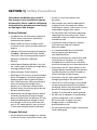
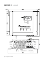
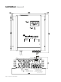
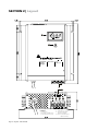
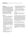
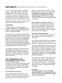
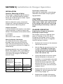
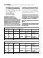
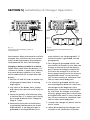
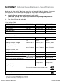
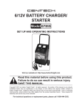
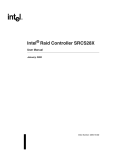
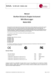
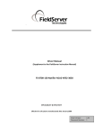
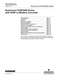
Owner's
Manual
Please read this
manual before
operating your
battery charger
Switch Mode,
Automatic, Lead
Acid Battery
Charger
MODELS:
SEC-1215UL
SEC-1230UL
SEC-2415UL
Section 1 | Safety Precautions
Hazardous conditions may result if
the charger is not installed or operated correctly. Please read the following
instructions to prevent personal injury
or damage to the charger:
• Install in a well ventilated, cool,
dry place.
Battery Related
• Do not block the ventilation openings
/ openings for the cooling fan. There
should be at least 6 inches clearance all
around the unit
• To reduce the risk of battery explosion,
follow these instructions and those
marked on the battery
• Never smoke or allow an open spark
or flame in the vicinity of the battery or
engine
• Charge only Lead Acid type of batteries
(Flooded / Absorbed Glass Mat (AGM)
/ Gel Cell). Do not charge other type of
batteries like Nickel Cadmium
(NiCad)
• Nickel-Metal Hydride (Ni-MH), Dry-Cell
etc. Other types of batteries might burst
causing personal injury
• Never charge a frozen battery
• Working in the vicinity of Lead Acid batteries is dangerous. Batteries generate
explosive gases during normal operation. Take necessary safety precautions
when installing the charger near a
battery or in a battery compartment
(Follow safety instructions given by the
battery manufacturer)
• Never place the charger directly above
or below the battery being charged;
gases or fluids from the battery will corrode and damage the charger. Locate
the charger as far away from the battery as DC cables permit. Do not install
in the same compartmentas batteries
Charger Related
• Do not operate the charger in a closedin area or restrict ventilation in any way.
• The charger must not be operated in
a damp or wet environment. When
mounting in a boat, make sure it is not
subjected to bilge water splash
• Installation and wiring must comply
with the local and the national
electrical codes.
• It is recommended that installation
and wiring may be done by a
certified electrician
• Wrong installation on a boat may lead
to corrosion of the boat. It is recommended that installation on the boat
must be carried out by a boat electrician
• Disconnect the AC input power to the
charger before connecting / disconnecting the batteries or other DC loads or
when working on the charger
• Disconnect the AC input power before
changing setting of the DIP Switch
• The chassis of the charger is connected
to the earth ground pin of the power
cord plug. Ensure that the earth ground
pin of AC receptacle feeding the
charger is connected to earth ground
• Do not use an adapter. If a grounding
type of receptacle is not available,
do not use this charger until the
proper outlet is installed by a
qualified electrician.
• Do not operate the charger if the power
cord is damaged
SECTION 2 | Layout
1
2
Automatic 12V - 15A Model
SEC-1215UL
Battery
Charger
4
3
5
6
7
8
- + + +
LEGEND:
1 - Ammeter
2 - Red LED for ON status
3 - AC input power cord
Fig. 2.1: Layout - SEC-1215UL
4 - DIP Switches S1, S2
5 - Common Negative
Output Terminal
6, 7 & 8 - Isolated Positive
Bank Terminals
Section 2 | Layout
1
2
Automatic 12V - 30A Model
SEC-1230UL
Battery
Charger
4
5
3
LEGEND:
1 - Ammeter
2 - Red LED for ON status
3 - AC input power cord
Fig. 2.2: Layout - SEC-1230UL
6
7
8
- + + +
4 - DIP Switches S1, S2
5 - Common Negative
Output Terminal
6, 7 & 8 - Isolated Positive
Bank Terminals
SECTION 2 | Layout
1
2
Automatic 24V - 15A Model
SEC-2415UL
Battery
Charger
4
5
3
LEGEND:
1 - Ammeter
2 - Red LED for ON status
3 - AC input power cord
Fig. 2.3: Layout - SEC-2415UL
6
7
8
- + + +
4 - DIP Switches S1, S2
5 - Common Negative
Output Terminal
6, 7 & 8 - Isolated Positive
Bank Terminals
SECTION 3 | Description, Features & Cooling
Description
These chargers are used to charge Lead
Acid Batteries (Flooded, AGM or Gel Cell).
SEC-1215UL (Maximum charging current
15A) and SEC-1230UL (Maximum charging current 30A) are used to charge 12 V
batteries. SEC-2415UL (Maximum charging
current 15A) is used to charge 24 V batteries. These chargers can be powered from
AC power source of either 120 V,
60 Hz (Pre-set) or 230 V, 50 Hz (By
changing jumper position inside the
unit - See page 10 for instructions).
Features
• State of the art switched mode technology is used for very high efficiency,
lightweight and quiet operation.
• User selectable AC input voltage 120 V , 60 Hz (Pre-set) or 230 V , 50 Hz
(By changing jumper position inside the
unit (See page 10 for instructions).
• User selectable 2 or 3 stage charging
algorithm ensures rapid and safe charging of all types of lead acid batteries
- Flooded, AGM, Gel Cell or batteries
with external load. (Through externally
accessible DIP Switch - see pages 11 for
instructions)
• Fully automatic "Connect and Forget"
operation
• 3 banks of batteries can be charged
simultaneously without use of an
external battery isolator
• Monitoring through ON status LED
and Ammeter
• Temperature controlled cooling fan
(SEC-1230UL, SEC-2415UL)
• Protections against short circuit, over
current, reverse battery connection and
over temperature (over temperature for
SEC-1230UL and SEC-2415UL)
• Can be used as a power supply or as
a DC UPS (Uninterruptible DC Power
Supply) when used with a battery (DIP
Switch set at "Battery with load")
Cooling
SEC-1215UL is cooled by convection and
does not have any thermal overload
shut down.
SEC-1230UL and SEC-2415UL are cooled by
convection and in addition, have a temperature controlled fan for forced air cooling. Two temperature sensors mounted on
the power transformer control the switching of the fan and over temperature shut
down. The fan will be switched on by the
first temperature sensor when the power
transformer reaches 70°C.
Hence, at lower loads, the fan may not
cut in and will be off. This is normal.
In case the fan fails or if the cooling is not
adequate, the second temperature sensor will shut down the unit if the power
transformer reaches 100°C. The red LED
will switch off. The unit will automatically
recover on removal of thermal overload
condition.
Section 4 | Charging States & Protections
NOTES:
1. Voltage Readings On No Load
The output has one common Negative terminal and three Positive terminals for charging 3 banks of batteries. Each Positive terminal has an internal isolating diode in series
which has a forward voltage drop of 0.8 to 1.1 V. On no load (that is when no battery
or other DC load is connected to any of the 3 terminals) , the voltage reading will
read 0.8 to 1.1 V higher than the specified float voltage. Note that the specified float
voltage is at a load of 1 A. Also, the voltage on the terminals not connected to the
load (for example, when one bank of battery is connected to one Positive terminal,
the other 2 Positive terminals will remain disconnected) will read 0.8 to 1.1 Volt higher
than the voltage of the loaded terminal.
2.VOLTAGE SPECIFICATIONS
All rated voltages are specified at battery temperature of 80°F.
These chargers can be manually selected
to operate in 3 stage or 2 stage modes
(Please see "Selecting the Type of Battery
and Charging Stages" . The
charging stages are described below:
restored (Note: The percentage capacity restored till the point the battery
reaches the Boost or Absorption Voltage is
inversely proportional to the value of the
bulk charge current.)
Stage 1 - Constant Current or
Bulk Charge Stage
Stage 2 - Constant Voltage Boost
or Absorption Stage
When the battery is low, it will try to
draw larger charging current. The charger
senses the current draw and limits this
to the maximum permissible value (15A
for SEC-1215UL / SEC-2415UL and 30A for
SEC-1230UL). Bulk charging takes place at
this constant current. In this condition of
constant current, the voltage measured
at the charger or battery terminals will be
the battery's own voltage.
As explained above, when the battery
voltage approaches the point where
battery "gassing" can begin, the charger
automatically switches over to the "Boost
or Absorption Stage". The charger applies
a constant voltage whose value depends
upon the type of battery selected (See DIP
Switch Settings). This controlled overcharge restores the balance 20% of the
capacity in a minimum amount of time. As
the capacity is fully restored, the charging
current starts reducing. When the current
reduces below the preset threshold, the
charger automatically switches to the
"Float or Maintenance Stage".
The constant current injected into the
battery starts restoring the battery capacity and it's voltage starts rising. When
this voltage approaches the threshold
of battery "gassing", termed "Boost or
Absorption Voltage", the charger automatically switches over to Stage 2 - "Boost
or Absorption Stage". The value of this
voltage depends upon the type of battery
being charged (See DIP Switch Settings).
By this time, approximately 80% of the
battery capacity will normally have been
Stage 3 - Constant Voltage , Float
or Maintenance Charging Stage
As explained above, as the charging current drops below the preset threshold
(1.5 to 2 amps for SEC-1215UL / SEC-2415UL
and 2.5 A to 3 A for SEC-1230UL), it signals
that the battery is 100% charged.
SECTION 4 | Charging States & Protections
In this "Float or Maintenance Charging
Stage", the charger outputs a constant
voltage of 13.5 V for 12 V system and
27 V for 24 V system. This helps in maintaining 100% capacity of the battery and
also compensates for self discharge. The
battery can remain connected in this stage
indefinitely without the risk of overcharging or excessive loss of electrolyte.
CAUTION!
3 stage charging is recommended for
charging stand-alone, unloaded batteries
(there is no load connected to the battery
when it is being charged).
If a load is also connected simultaneously, a
part of the charger's output current will be
diverted to thIs load. Thus, the charger may
remain locked in the "Boost or Absorption
Mode" if the current drawn by the load is
more than the preset value of threshold
current determining change over between
the Boost and Float Stages. This will lead to
overcharging and loss of electrolyte.
For charging a battery when a load is also
connected simultaneously, the "Boost or
Absorption Stage" is required to be disabled. Select "Battery with Load" using the
DIP switch. See details under "Powering
other DC Loads"
The charger has the
following protections:
Short Circuit Shut Down
In case of a short circuit on the output side,
the charger will shut down. The Red LED
will switch off. The charger will automatically recover once the short circuit condition is removed.
Over load Current Limiting
The current drawn by the load is automatically limited to a maximum of 15 A
for SEC-1215UL / SEC-2415UL and 30 A for
SEC-1230UL. If the load tries to draw a
higher current than these limits, the output voltage of the unit will start to drop.
If a battery is connected, the output
voltage will be clamped to the actual
battery voltage. The unit will automatically recover when the overload condition
is removed.
Reverse Battery Connection Cut Off
The output is internally fused on the DC
side. In case, the polarity of the battery
connection is reversed, the fuse(s) will
blow . The red LED will switch off. The
fuse(s) will be required to be replaced for
the unit to function again.
Thermal Overload Shutdown
SEC-1215UL is cooled by convection and
does not have any thermal overload
shut down.
SEC-1230UL and SEC-2415UL are cooled by
convection and in addition, have a temperature controlled fan for forced air cooling. Two temperature sensors mounted on
the power transformer control the switching of the fan and over temperature shut
down. The fan will be switched on by the
first temperature sensor when the power
transformer reaches 70°C. Hence, at lower
loads, the fan may not cut in and will be
off. This is normal.
In case the fan fails or if the cooling is not
adequate, the second temperature sensor will shut down the unit if the power
transformer reaches 100°C. The red LED
will switch off. The unit will automatically
recover on removal of thermal overload
condition.
CAUTION:
Keep the charger in a well ventilated,
cool and open area. Do not block the vent
holes on the sides or the discharge openings of the cooling fan.
SECTION 5 | Installation & Charger Operation
Installation
Location, Mounting & Safety
The charger is required to be installed in
a safe, well ventilated and dry location.
Please see the details given under "Important Safety Instructions"
With the help of 4 screws, mount the
charger on a vertical bulkhead with the
output terminal side facing down.
Output connectors
A terminal block with tubular, screw down
type of terminals is used for output connection. The diameter of the tubular holes
is as follows :
SEC-1215UL
0.14 inches
SEC-2415UL / SEC-1230UL
0.19 inches
Wires for Battery Connection
To avoid polarity errors and possible
damage, never use wires of only one
color. Use red insulated wire(s) for Positive connection(s) and black for Negative
connection(s)
Recommended DC wire sizes are given
below. The length in feet is the length of
the pair of the Positive and Negative DC
wires from the charger to the battery /
other DC load:
Length of
the pair of
the Positive
& Negative
cables
SEC-1215UL
SEC-2415UL
0 to 6 ft.
AWG #10
AWG #8
6 to 10 ft.
AWG #8
AWG #6
10 to 20 ft.
AWG #6
AWG #4
Termination of Wire Ends
Wire ends for connection to the charger
should be terminated with pin type of
lugs provided.
CAUTION!
For firm connection when using stranded
cable, crimp / solder "pin" style terminal
on the charger end of the DC wires used
for connecting to the battery / other DC
loads.
Charger Operation
Preparing the Charger for Operation:
Selecting AC input voltage
The charger is pre-set to operate from
input AC voltage of 120 VAC, 60 Hz.
To operate the charger from AC input
voltage of 230 VAC, 50 Hz, change the
internal setting as follows:
1.
Remove the 4 screws on the ammeter
side of the top cover
2.
Gently slide the top cover out by 2 to
3 inches. (Caution! The top cover
will be restrained from fully sliding
out by the wires connecting the ammeter, LED and the fan)
3.
Locate the jumper wire with a quick
female disconnect. In the pre-set
condition, it is connected to the male
vertical pin marked "115 V". Pull this
female disconnect upwards to disconnect from the "115 V" position.
Connect this to the male vertical pin
marked "230 V"
4.
Replace the fuse with the fuse recommended for 230 VAC operation (See
fuse rating at page 17)
5.
Replace the AC plug of the power
cord with a suitable 3 pin grounded
SEC-1230UL
SECTION 5 | Installation & Charger Operation
the battery. A DIP Switch is provided on
top of the output terminals for selecting
the battery type and for disabling the
Boost Stage when charging loaded batteries. The following selections can be made
with the help of the DIP Switch.
plug to mate with the 230 VAC outlet. Caution: The new plug should
have 3 poles i.e. Line (L) , Neutral(N)
and Earth ground. Color code for the
power cord conductors is:
- Line (L) - Black
- Neutral (N) - White
- Earth ground - Green
CAUTION! Do not change the DIP Switch
setting when the charger is operating. Always change the DIP Switch setting when
the charger is off, i.e. after disconnecting
the charger from the AC input power.
Preparing The Charger For
Operation: Selecting The Type
Of Battery And Charging Stages
The Float Voltage and Boost Voltage (Also
called Absorption or Overcharge Voltage)
of different types of Lead Acid Batteries
are different. Also, when a charger is used
to charge a battery and simultaneously
supply a load , the Boost Stage is required
to be disabled to prevent overcharging of
NOTE: The voltages are for a temperature
of 80°F.
CAUTION! Please ensure that the position
No. 4 of the DIP switch (S1-ON & S2-ON) is
NEVER selected.
DIP Switch Settings: SEC-1215UL/SEC-1230UL
Float
Battery
Type
Boost
Charging
Stages
S1
S2
OFF *
ON *
13.5 V *
14.4 V *
Flooded /
AGM *
3 Stages
(Stages 1, 2, 3)
ON *
OFF
13.5 V
14.0 V
Gel Cell
3 Stages
(Stages 1, 2, 3)
OFF
OFF
13.5 V
Disabled
Battery with
Load
2 Stages
(Stages 1, 3)
ON
ON
Caution! Do NOT use this setting
* Factory pre-set in this position
DIP SWITCH SETTINGS - SEC-2415UL
S1
S2
Float
Boost
Battery Type
Charging
Stages
OFF *
ON *
27 V *
28.8 V *
Flooded /
AGM *
3 Stages
(Stages 1, 2, 3)
ON
OFF
27 V
28.0 V
Gel Cell
3 Stages
(Stages 1, 2, 3)
OFF
OFF
27 V
Disabled
Battery with
load
2 Stages
(Stages 1, 3)
ON
ON
Caution! Do not use this setting
* Factory pre-set in this position
SECTION 5 | Installation & Charger Operation
Connecting The Batteries or
Other Dc Loads
The output has a common Negative (-)
terminal and 3 Positive terminals for
charging up to 3 independent banks of
batteries. Each Positive connector has it's
own internal isolating diode which works
as a battery isolator. If more than one bank
of batteries is connected, these will be
charged at the same time as long as the
AC power is available to the charger (the
maximum charging current of 15 A of
SEC-1215UL/SEC-2415UL and 30 A of
SEC-1230UL will be shared among the
connected banks of the batteries depending upon their discharged states). In case
the AC power fails or if there is no output
from the charger, the isolating diodes will
prevent charging / discharging among the
batteries connected to the banks.
The above arrangement works as a battery
isolator and can divide the charging current into a maximum of 3 isolated branches
and allows current flow in each branch in
one direction only. If more than one battery systems are being used independently,
the system batteries will discharge to
different levels. If system batteries are connected in parallel to charge from a single
charger, a weak or a dead battery will drain
the charge from the strong battery. Such
situation occurs in RVs, boats and other
vehicles where 2 separate battery systems
are used – starter battery for starting and
running the engine and the other auxiliary
/ house battery system for running auxiliary
devices like inverters, refrigerators, car
stereos etc. Here, the starter battery should
be connected to one bank and the auxiliary
/ house battery to the second bank. Fig. 5.1
shows this connection.
In a single battery bank, two or more
batteries may be connected in parallel to
increase their AH capacity. These will be
discharged and charged as a single battery
bank. In this case, the paralleled bank of
multiple batteries is to be considered as
a single bank and connected to any one
of the 3 banks of the charger as shown in
Fig. 5.2 for bank of 4 batteries. For proper
charging of all the batteries, please ensure
that the Positive wire “A” from the charger
is connected to the Positive terminal of the
first battery (Battery 1) and the Negative
wire “B” is connected to the Negative
terminal of the last battery (Battery 4). This
will ensure the following:
• Resistance of the interconnecting cables
will be balanced and the individual batteries will see the same series resistance
• All the individual batteries will be
charged at the same charging current
and thus will be charged to the same
state of charge
• None of the batteries will see an overcharge condition
When connecting a single battery or other
single DC load, it can be connected to the
common Negative and any one of the 3
Positive terminals as in Fig. 5.2.
Operation
When the charger is switched on, the
red LED lights up indicating that output
voltage is available. When the batteries
are being charged or when the charger
is supplying other DC load, the current
fed by the charger will be indicated by
the ammeter.
When the batteries are discharged, they
will draw charging current proportional
to their discharged condition (up to a
maximum current rating of the charger)
and this current draw will be shown by
SECTION 5 | Installation & Charger Operation
- +++
- +++
Positive
Wire “A”
Starter
Battery
Auxilary /
House
Battery
Negative
Wire “B”
Battery 4
Fig. 5.1:
Connecting 2 separate battery systems to
2 separate banks.
the ammeter. When the batteries are fully
charged, they will draw very low current
(may not be registered by the ammeter)
to compensate for their self discharge.
Charging a Battery Installed in a Vehicle
Follow these steps when the battery is installed in a vehicle. A spark near a battery
may cause battery explosion. For safety
and to reduce the risk of spark near the
battery:
1. Position AC and DC cords to reduce risk
of damage by hood, door or moving
engine parts
2. Stay clear of fan blades, belts, pulleys
and other parts that can cause injury to
persons
3. Check the polarity of the battery posts.
A Positive (Pos, P, +) battery post usually
has a larger diameter than a Negative
(Neg, N, -) post
4. Determine which post of the battery
is grounded (Connected to the chassis
Engine Block). If the Negative post is
grounded to the Engine Block (As in
Battery 3
Battery 2
Battery 1
Fig. 5.2:
Connecting bank of paralleled batteries to
single bank.
most vehicles), see sub paragraph 5. If
the Positive post is grounded, see sub
paragraph 6)
5. For a Negative grounded vehicle, connect the Positive (red) DC wire from the
charger to the Positive of the battery
post. Connect the Negative (black) DC
wire from the charger to a section of
heavy gauge metal part of the frame or
engine block which is away from battery. Do not connect to carburetor, fuel
lines or sheet metal body parts.
6. For a Positive grounded vehicle, connect the Negative (black) DC wire from
the charger to the Negative of the
battery post. Connect the Positive (red)
DC wire from the charger to a section
of heavy gauge metal part of the frame
or engine block which is away from battery. Do not connect to carburetor, fuel
lines or sheet metal body parts.
7. Connect the charger AC power cord to
the AC outlet
8. When disconnecting the charger, turn
switches to off, disconnect AC power
SECTION 5 | Installation & Charger Operation
cord, remove connection from the vehicle chassis and then remove connection
from the battery terminal
Charging a Battery outside the Vehicle
Follow these steps when the battery is
outside the vehicle. A spark near the
battery may cause battery explosion. For
safety and to reduce risk of spark near the
battery, connect the charger as follows:
1. Check the polarity of the battery posts.
A Positive (Pos, P, +) battery post usually
has a larger diameter than a Negative
(Neg, N, -) post
2. Attach a piece of at least 3" of AWG #6
insulated battery wire to the Negative
battery post
3. Connect the Positive (red) DC wire from
the charger to the Positive battery post
4. Position yourself and the free end of
the piece of wire attached to the Negative post as far away from the battery as
possible and then connect the Negative
(black) DC wire from the charger to the
free end of the piece of wire attached
to the Negative battery post
5. Do not face the battery when making
the final connection
6. Connect the charger AC power cord
to the AC outlet
7. When disconnecting the charger,
always do so in reverse sequence of
connecting procedure and break the
first connection while standing as far
away from the battery as practical
Charging more than one
bank of batteries
CAUTION! When charging more than one
bank of batteries at the same time using
3 Stage Charging, ensure that the batteries
in the banks are in a similar discharged
condition. If one bank is completely
discharged and another is almost fully
charged, the bank that is fully charged
will be subjected to over charge condition
during the time when the charger remains
in Boost Stage for charging the completely
discharged bank. If batteries are in dissimilar states of charge, select DIP Switch
setting for "Battery with Load."
Powering Other DC Loads
The charger can be used as a power supply or as a DC UPS . For both these applications, first set the DIP Switch to "Battery
with load". (See under " Selecting the
Type of Battery and Charging Stages")
To use as a power supply, first switch
off the DC load. Connect the DC load
between the common Negative terminal
and one of the three Positive terminals.
Ensure that the maximum current drawn
by the DC load is below the maximum
current rating of the charger. Switch on
the charger and then the DC load.
In a DC UPS (Un-interruptible Power Supply) , the charger simultaneously powers
the DC load as well as the battery. As long
as the AC power to the charger is available and the charger is working normally,
the charger will supply the DC load as well
as charge/float the battery. In case the AC
power fails or if the charger stops work-
SECTION 5 | Installation & Charger Operation
ing, the battery will automatically power
the DC load. As soon as the AC power to
the charger is restored , the DC load will
once again be fed by the charger and at
the same time the battery will be
recharged.
To use as a DC UPS, first switch off the
DC load and connect it to the battery.
Now connect the battery as explained
above under "Charging a Battery outside
the Vehicle" Switch on the
charger and then switch on the DC load.
CAUTION! Please ensure that the sum of
the current drawn by the DC load and the
current desired for charging the battery is
less than the maximum current capacity
of the charger.
SECTION 6 | Troubleshooting
SYMPTOMS: CHARGER POWERED
AND CONNECTED TO THE BATTERY
battery may be loose or open. Check tightness
and continuity of the battery connection.
The Red Led Is Off
The DC side fuse may have blown due to
wrong polarity of battery connection.
Ensure Positive of the battery is connected
to the Positive of the charger and the
Negative of the battery is connected to
the Negative of the charger. Check the
fuses inside the charger and replace, if
blown.
The Battery Is Getting Over
Charged or Boils
The charger is also feeding other DC
load(s) in parallel with the battery. The
DIP Switch is not selected for "Battery
with Load". Change DIP Switch setting to
"Battery with Load" (see under "Powering
other DC loads"
The battery may be shorted. In this condition, the unit is shut down by the short
circuit protection circuit. Remove the
battery connection. If the red LED now
comes on, the battery is shorted. If the red
LED still does not come on, check if there
is AC power in the receptacle. If there is
power, check the AC side fuse inside the
unit. If the fuse is not blown, call Technical
Support.
The Red Led Is On but the Ammeter
Shows No Reading
The battery is fully charged. If the battery
is not fully charged, the connection to the
SYMPTOMS: CHARGER POWERED
& DISCONNECTED FROM BATTERY
The Red Led Is Off
Check there is AC power in the receptacle.
If there is power, check the AC side fuse
inside the unit. If the fuse is not blown,
check the DC side fuse. If the DC side fuse
is not blown, the output may be shorted.
In this condition, the charger is shut down
by the short circuit protection circuit.
Check that the output terminals are not
shorted. If the terminals are not shorted,
call Technical Support.
SECTION 6 | Troubleshooting
Ac Side Fuse Blows As Soon As
Power Is Turned On
The AC input is selected for 120 VAC but
the unit is plugged into 230 VAC. Always
check that the charger is set for the correct AC mains voltage. If the AC input
voltage is correct, the charger is defective.
Call Technical Support.
Dc Side Fuse Blows As Soon
As The Battery Is Connected
Wrong polarity of the battery connection.
Ensure Positive of the battery is connected
to the Positive of the charger and the
Negative of the battery is connected to
the Negative of the charger.
Symptoms When The Charger
Is Powered And Is Being Used
As A Dc Power Supply/Ups
The Voltage Drops When Load Is Switched On
The load is trying to draw current more
than the current limit value of the charger
(the current limit value is the maximum
specified charging Amps). Once the load
current reaches the current limit value,
the current limit circuit is activated and
the output voltage drops. Some loads
like motors, compressors, incandescent
lamps, halogen lamps, heating elements,
relays, coils, capacitors etc. draw very large
inrush/starting currents which may reach
up to 10 times their normal operating
currents. Ensure that the starting / inrush
current or the maximum operating current of the load is lower than the current
limit value of the charger.
SECTION 7 | Internal Fuse Ratings & Specifications
Both the AC side and DC sides have fuses that are located inside the charger. Disconnect
the AC power when checking or changing the fuses. Open the charger as follows:
1. Remove the 4 screws on the ammeter side of the top cover
2. Gently slide the top cover out by about 2 to 3 inches.
(CAUTION! The top cover will be restrained from fully sliding out by the wires
connecting the ammeter , LED and fan)
3. The fuses will now be accessible
Fuse Ratings Table
FUSE RATINGS
SEC-1215UL
SEC-1230UL
SEC-2415UL
120 VAC INPUT
4A / 125V
8A / 125V
8 A / 125V
DC OUTPUT
20A / 32V
2 x 20A / 32V
2 x 10A / 32V
230 VAC INPUT
2A / 250V
4A / 250V
4A / 250V
DC OUTPUT
20A / 32V
2 x 20A / 32V
2 x 10A/32V
Specifications Table
Specifications
SEC-1215UL
SEC-1230UL
SEC-2415UL
Nominal Input Voltage (pre-set)
120 VAC, 60 Hz,
3.3A
120 VAC, 60 Hz,
6.5A
120 VAC, 60 Hz,
6.5A
Internal Jumper Change
230 VAC, 50 Hz
230 VAC, 50 Hz
230 VAC, 50 Hz
Input Frequency
50 - 60 Hz
50 - 60 Hz
50 - 60 Hz
Output Voltage, Boost 1,2
14 VDC, or 14.4
VDC or disabled
14 VDC, or 14.4
VDC or disabled
28 VDC, or 28.8
VDC or disabled
Output Voltage, Float1
13.5 VDC
13.5 VDC
27.0 VDC
Output Amps
15A
30A
15A
Operating Temperature Range
0 - 40°C
0 - 40°C
0 - 40°C
Weight
2.2 kg. / 4.8 lbs.
2.9 kg. / 6.4 lbs.
2.9 kg. / 6.4 lbs.
Housing Dimensions
(L x W x H) Inches / Millimetres
8.5 x 8.4 x 3.3 /
218 x 214 x 83
10.8 x 8.4 x 3.3 /
280 x 214 x 83
10.8 x 8.4 x 3.3 /
280 x 214 x 83
Protections
Short Circuit
Overload
Short Circuit
Overload / Over
Temperature
Short Circuit
Overload / Over
Temperature
Output Banks
3
3
3
Safety Compliance
i) Conforms to ANSI/UL STD 1564
ii) Certified to CAN/CSA STD C22.2 No. 107.2
4004711
EMI Compliance
FCC Part 15(B), Class B
1. Voltages based on battery temperature of 80° F
2. Based on selection by DIP SWITCH. See pages 8 & 9
Specifications are subject to change without notice.
SAMLEX AMERICA BATTERY
CAR BATTERIES