1
BT1100
2002
5JN1-AE1
SERVICE MANUAL
EASB0000
BT1100 2002
SERVICE MANUAL
© 2001 by Belgarda S.p.A.
First edition, November 2001
All rights reserved. Any reproduction or
unauthorized use without the written
permission of Belgarda S.p.A.
is expressly prohibited.
Printed in Italy
EASB0001
NOTICE
This manual was produced by the Belgarda S.p.A. primarily for use by Yamaha dealers and their qualified mechanics. It is not possible to include all the knowledge of a mechanic in one manual. Therefore,
anyone who uses this book to perform maintenance and repairs on Yamaha vehicles should have a basic
understanding of mechanics and the techniques to repair these types of vehicles. Repair and maintenance work attempted by anyone without this knowledge is likely to render the vehicle unsafe and unfit
for use.
Belgarda S.p.A. is continually striving to improve all of its models. Modifications and significant changes
in specifications or procedures will be forwarded to all authorized Yamaha dealers and will appear in
future editions of this manual where applicable.
NOTE:
Designs and specifications are subject to change without notice.
EAS00004
IMPORTANT MANUAL INFORMATION
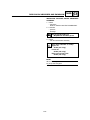
Particularly important information is distinguished in this manual by the following.
The Safety Alert Symbol means ATTENTION! BECOME ALERT! YOUR SAFETY IS INVOLVED!
WARNING
CAUTION:
NOTE:
Failure to follow WARNING instructions could result in severe injury or death to
the motorcycle operator, a bystander or a person checking or repairing the
motorcycle.
A CAUTION indicates special precautions that must be taken to avoid damage
to the motorcycle.
A NOTE provides key information to make procedures easier or clearer.
EAS00007
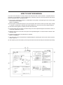
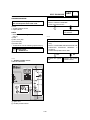
HOW TO USE THIS MANUAL
This manual is intended as a handy, easy-to-read reference book for the mechanic. Comprehensive explanations of all installation, removal, disassembly, assembly, repair and check procedures are laid out
with the individual steps in sequential order.
1 The manual is divided into chapters. An abbreviation and symbol in the upper right corner of each page
indicate the current chapter.
Refer to "SYMBOLS".
2 Each chapter is divided into sections. The current section title is shown at the top of each page, except
in Chapter 3 ("PERIODIC CHECKS AND ADJUSTMENTS"), where the sub-section title(s) appears.
3 Sub-section titles appear in smaller print than the section title.
4 To help identify parts and clarify procedure steps, there are exploded diagrams at the start of each removal and disassembly section.
5 Numbers are given in the order of the jobs in the exploded diagram. A circled number indicates a disassembly step.
6 Symbols indicate parts to be lubricated or replaced.
Refer to "SYMBOLS".
7 A job instruction chart accompanies the exploded diagram, providing the order of jobs, names of parts,
notes in jobs, etc.
8 Jobs requiring more information (such as special tools and technical data) are described sequentially.
EB003000
1
2
GEN
INFO
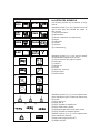
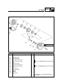
ILLUSTRATED SYMBOLS
3
4
INSP
ADJ
ENG
5
6
CARB
CHAS
7
8
TRBL
SHTG
ELEC
9
0
q
w
e
r
t
y
u
i
o
p
a
s
d
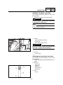
The following symbols are not relevant to every
vehicle.
Illustrated symbols 1 to 8 are printed on the top
right of each page and indicate the subject of
each chapter.
1 General information
2 Specifications
3 Periodic inspections and adjustments
4 Engine
5 Carburetion
6 Chassis
7 Electrical
8 Troubleshooting
SPEC
?
f
New
Illustrated symbols 9 to y are used to identify
the specifications appearing in the text.
9 Can be serviced with engine mounted
0 Filling fluid
q Lubricant
w Special tool
e Torque
r Wear limit, clearance
t Engine speed
y Electrical data
Illustrated symbols u to s in the exploded diagrams indicate the types of lubricants and lubrication points.
u Apply engine oil
i Apply gear oil
o Apply molybdenum disulfide oil
p Apply wheel bearing grease
a Apply lightweight lithium-soap base grease
s Apply molybdenum disulfide grease
Illustrated symbols d to f in the exploded diagrams indicate the following:
d Apply locking agent (LOCTITE®)
f Replace the part
E004000
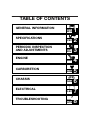
TABLE OF CONTENTS
GENERAL INFORMATION
SPECIFICATIONS
PERIODIC INSPECTION
AND ADJUSTMENTS
ENGINE
CARBURETION
CHASSIS
ELECTRICAL
TROUBLESHOOTING
GEN
INFO
1
SPEC
2
INSP
ADJ
3
ENG
4
CARB
5
CHAS
6
ELEC
7
?
TRBL
SHTG
8
GEN
INFO
1
GEN
INFO
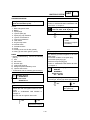
CHAPTER 1.
GENERAL INFORMATION
MOTORCYCLE IDENTIFICATION ......................................................................................1-1
VEHICLE IDENTIFICATION NUMBER..........................................................................1-1
MODEL LABEL ..............................................................................................................1-1
IMPORTANT INFORMATION ..............................................................................................1-2
PREPARATION FOR REMOVAL PROCEDURES ........................................................1-2
REPLACEMENT PARTS ..............................................................................................1-2
GASKETS, OIL SEALS AND O-RINGS ........................................................................1-2
LOCK WASHERS/PLATES AND COTTER PINS ........................................................1-3
BEARINGS AND OIL SEALS ........................................................................................1-3
CIRCLIPS ......................................................................................................................1-3
CHECKING OF CONNECTIONS ........................................................................................1-4
SPECIAL TOOLS..................................................................................................................1-5
GEN
INFO
MOTORCYCLE IDENTIFICATION
GEN
INFO
EB100010
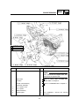
GENERAL INFORMATION
MOTORCYCLE IDENTIFICATION
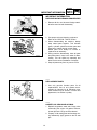
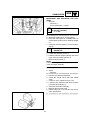
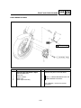
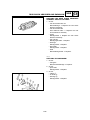
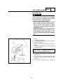
VEHICLE IDENTIFICATION NUMBER
1
The vehicle identification number 1 is stamped
into the frame under the seat.
MODEL LABEL
1
The model label 1 is affixed to the frame under
the seat.
This information will be needed to order spare
parts.
1-1
IMPORTANT INFORMATION
GEN
INFO
EB101000
IMPORTANT INFORMATION
PREPARATION FOR REMOVAL PROCEDURES
1. Remove all dirt, mud, dust and foreign material before removal and disassembly.
2. Use proper tools and cleaning equipment.
Refer to the “SPECIAL TOOLS” section.
3. When disassembling the machine, always
keep mated parts together. This includes
gears, cylinders, pistons and other parts that
have been “mated” through normal wear.
Mated parts must always be reused or
replaced as an assembly.
4. During machine disassembly, clean all parts
and place them in trays in the order of disassembly. This will speed up assembly and
allow for the correct installation of all parts.
5. Keep all parts away from any source of fire.
EB101010
REPLACEMENT PARTS
1. Use only genuine Yamaha parts for all
replacements. Use oil and grease recommended by Yamaha for all lubrication jobs.
Other brands may be similar in function and
appearance, but inferior in quality.
EB101020
GASKETS, OIL SEALS AND O-RINGS
1. Replace all gaskets, seals and O-rings when
overhauling the engine. All gasket surfaces,
oil seal lips and O-rings must be cleaned.
2. Properly oil all mating parts and bearings during reassembly. Apply grease to the oil seal
lips.
1-2
IMPORTANT INFORMATION
GEN
INFO
EB101030
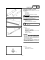
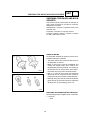
LOCK WASHERS/PLATES AND COTTER PINS
1. Replace all lock washers/plates 1 and cotter
pins after removal. Bend lock tabs along the
bolt or nut flats after the bolt or nut has been
tightened to specification.
OR
EB101040
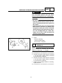
BEARINGS AND OIL SEALS
1. Install bearings and oil seals so that the manufacturer’s marks or numbers are visible.
When installing oil seals, apply a light coating
of lightweight lithium base grease to the seal
lips. Oil bearings liberally when installing, if
appropriate.
1 Oil seal
CAUTION:
Do not use compressed air to spin the bearings dry. This will damage the bearing surfaces.
1 Bearing
EB101050
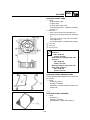
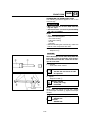
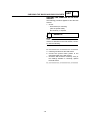
CIRCLIPS
1. Check all circlips carefully before reassembly.
Always replace piston pin clips after one use.
Replace distorted circlips. When installing a
circlip 1, make sure that the sharp-edged
corner 2 is positioned opposite the thrust 3
it receives. See sectional view.
4 Shaft
1-3
CHECKING OF CONNECTIONS
GEN
INFO
EB801000
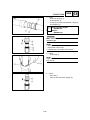
CHECKING OF CONNECTIONS
Check the connectors for stains, rust, moisture,
etc.
1. Disconnect:
• connector
2. Check:
• connector
Moisture → Dry each terminal with an air
blower.
Stains/rust → Connect and disconnect the
terminals several times.
3. Check:
• connector leads
Looseness → Bend up the pin 1 and connect the terminals.
4. Connect:
• connector terminals
NOTE:
The two terminals “click” together.
5. Check:
• continuity (using a pocket tester)
NOTE:
• If there is no continuity, clean the terminals.
• When checking the wire harness be sure to perform steps 1 to 3.
• As a quick remedy, use a contact revitalizer
available at most part stores.
• Check the connector with a pocket tester as
shown.
1-4
SPECIAL TOOLS
GEN
INFO
EB102001
SPECIAL TOOLS
The following special tools are necessary for complete and accurate tune-up and assembly. Use only the
appropriate special tools; this will help prevent damage caused by the use of inappropriate tools or
improvised techniques. Special tools may differ by shape and part number from country to country. In
such a case, two types are provided.
When placing an order, refer to the list provided below to avoid any mistakes.
Tool No.
Weight
90890-01084
Bolt
90890-01085
Tool name/How to use
Slide hammer bolt/weight
These tools are used to remove the rocker
arm shaft.
Crankcase separating tool
90890-01135
This tool is used to remove the crankshaft.
Coupling gear/middle shaft tool
90890-01229
This tool is needed when removing or
installing the final pinion shaft nut.
Final gear
backlash band
90890-01230
Middle gear
backlash band
90890-01231
Final gear backlash band
This tool is needed when measuring final
gear/middle gear backlash.
Crankshaft installer pot/bolt/adapter/spacer
Installer pot
90890-01274
Bolt
90890-01275
Adapter
90890-04130
Spacer
90890-04060
These tools are used to install the crankshaft.
Piston pin puller
90890-01304
This tool is used to remove the piston pin.
Fuel level gauge
90890-01312
This gauge is used to measure the fuel level
in the float chamber.
1-5
Illustration
SPECIAL TOOLS
Tool No.
Puller
90890-01362
Adapter
90890-04131
Weight
90890-01367
Adapter
90890-01374
T-handle
90890-01326
Holder
90890-01327
Ring nut wrench
90890-01403
Exhaust nut
wrench
90890-01268
Tool name/How to use
Flywheel puller/adapter
These tools are needed to remove the
rotor.
Fork seal
(Ø 43 mm)
driver
weight/adapter
These tools are needed when
installing the slide metal, oil seal and
dust seal into the fork.
T-handle/front fork damper rod holder
These tools are needed to loosen and
tighten the front fork damper rod
holding bolt.
Ring nut wrench/exhaust and steering
nut wrench
This tool is needed to loosen and tighten the steering stem ring nut.
Sheave holder
90890-01701
This tool is needed to hold the rotor
when removing or installing the rotor
bolt.
Compression gauge set
90890-03081
These tools are needed to measure
engine compression.
Vacuum gauge
90890-03094
This gauge is needed for carburetor
synchronization.
Pocket tester
90890-03112
This instrument is needed for checking
the electrical system.
Engine tachometer
90890-03113
This tool is needed for observing
engine r/min.
1-6
GEN
INFO
Illustration
SPECIAL TOOLS
Tool No.
Tool name/How to use
Timing light
90890-03141
This tool is necessary for checking
ignition timing.
Valve guide remover & installer
90890-04014
This tool is needed to remove and
install the valve guide.
Valve spring compressor
90890-04019
This tool is needed to remove and
install the valve assemblies.
Adapter
90890-01277
Shock puller
90890-01290
Weight
90890-01291
Crankshaft installer bolt adapter/armature shock puller/weight
These tools are needed when removing the final pinion shaft.
Bearing retainer wrench
90890-04137
Wrench
90890-04138
Holder
90890-04055
This tool is needed when removing or
installing the middle drive shaft
assembly.
Middle drive shaft nut wrench/Middle
drive shaft holder
These tools are needed when removing or installing the middle drive shaft
bearing.
Universal joint holder
90890-04062
This tool is needed when removing or
installing the driven pinion gear nut.
Bearing retainer wrench
90890-04077
This tool is needed when removing or
installing the final drive pinion gear
assembly.
Bearing retainer wrench
90890-04050
This tool is needed when removing or
installing the final shaft drive bearing
retainer.
1-7
GEN
INFO
Illustration
ATTREZZI SPECIALI
Tool No.
Tool name/How to use
Clutch holding tool
90890-04086
This tool is needed to hold the clutch
when removing or installing the clutch
boss nut.
Damper spring compressor
90890-04090
This tool is needed when removing or
installing the damper spring.
90890-06754
Dynamic spark tester
Ignition checker
This instrument is necessary for
checking the ignition system components.
Yamaha bond No.1215
90890-85505
This sealant (bond) is used on
crankcase mating surfaces, etc.
1-8
GEN
INFO
Illustration
SPEC
2
SPEC
CHAPTER 2.
SPECIFICATIONS
GENERAL SPECIFICATIONS ............................................................................................ 2-1
MAINTENANCE SPECIFICATIONS ....................................................................................2-4
ENGINE ........................................................................................................................2-4
CHASSIS ....................................................................................................................2-14
ELECTRICAL ..............................................................................................................2-18
GENERAL TORQUE SPECIFICATIONS............................................................................2-20
CONVERSION TABLE........................................................................................................2-20
LUBRICATION POINTS AND LUBRICANT TYPES..........................................................2-21
ENGINE ......................................................................................................................2-21
CHASSIS ....................................................................................................................2-22
LUBRICATION DIAGRAMS ..............................................................................................2-23
CABLE ROUTING ..............................................................................................................2-26
SPEC
GENERAL SPECIFICATIONS
SPEC
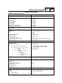
SPECIFICATIONS
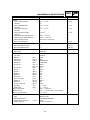
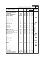
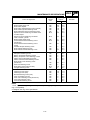
GENERAL SPECIFICATIONS
Item
Standard
Model code:
BT1100: 5JN1
Dimensions:
Overall length
Overall width
Overall height
Seat height
Wheelbase
Minimum ground clearance
Minimum turning radius
2,200 mm
800 mm
1,140 mm
812 mm
1,530 mm
168 mm
2,980 mm
Basic weight:
With oil and a full fuel tank
250.5 kg
Engine:
Engine type
Air cooled 4-stroke,
SOHC
V-type 2-cylinder
1.063 L
95 75 mm
8.3 : 1
1,000 kPa (10 kg/cm2, 10 bar) at 400 r/min
Electric starter
Cylinder arrangement
Displacement
Bore stroke
Compression ratio
Compression pressure (STD)
Starting system
Lubrication system:
Oil type or grade:
Engine oil
Temp.
Wet sump
API standard:
°C
API Service SE, SF, SG or higher
SAE 20W40SE or SAE 10W30SE
ACEA standard:
G4 or G5
Final gear oil:
SAE80 API “GL-4” Hypoid Gear Oil or multigrade
hypoid gear oil SAE 80W-90
Oil quantity:
Engine oil
Periodic oil change
With oil filter replacement
Total amount
Final gear case oil
Total amount
3.0 L
3.1 L
3.6 L
Air filter:
Dry type element
Fuel:
Type
Fuel tank capacity
Fuel reserve amount
Regular unleaded gasoline
20 L
5.8 L
0.2 L
2-1
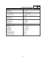
GENERAL SPECIFICATIONS
Item
Standard
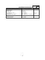
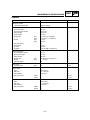
Carburetor:
Type/quantity
Manufacturer
BSR37/2
MIKUNI
Spark plug:
Type
Manufacturer
Spark plug gap
BPR7ES/W22EPR-U
NGK/DENSO
0.7 0.8 mm
Clutch type:
Wet, multiple-disc
Transmission:
Primary reduction system
Primary reduction ratio
Secondary reduction system
Secondary reduction ratio
Transmission type
Operation
Gear ratio
Spur gear
78/47 (1.660)
Shaft drive
44/47 19/18 32/11 (2.875)
Constant mesh 5-speed
Left foot operation
40/17 (2.353)
40/24 (1.667)
36/28 (1.286)
32/31 (1.032)
29/34 (0.853)
1st
2nd
3rd
4th
5th
Chassis:
Frame type
Caster angle
Trail
Twin tube Backbone
25°
106 mm
Tire:
Type
Size
Tubeless
120/70-ZR17 (58W)
170/60-ZR17 (72W)
DUNLOP / METZELER
DUNLOP / METZELER
D205F TL / MEZ3F TL
D205 TL / MEZ3 TL
front
rear
front
rear
front
rear
Manufacturer
Type
Maximum load-except motorcycle:
200 kg
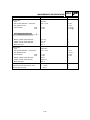
Tire pressure (cold tire):
0 ~ 90 kg load *
front
rear
90 kg (198 lb) ~ Maximum load * front
rear
Brake:
Front brake
Rear brake
SPEC
230 kPa (2.30 kg/cm2) (2.30 bar)
250 kPa (2.50 kg/cm2) (2.50 bar)
250 kPa (2.50 kg/cm2) (2.50 bar)
270 kPa (2.70 kg/cm2) (2.70 bar)
* Load is the total weight of the cargo, rider,
passenger and accessories.
type
operation
type
operation
Dual disc brake
Right hand operation
Single disc brake
Right foot operation
2-2
GENERAL SPECIFICATIONS
Item
SPEC
Standard
Suspension:
Front suspension
Rear suspension
Telescopic fork
Swingarm (link suspension)
Shock absorber:
Front shock absorber
Rear shock absorber
Coil spring/Oil damper
Coil spring/Gas-oil damper/Spring preload
adjustable
Wheel travel:
Front wheel travel
Rear wheel travel
130 mm
113 mm
Electrical system:
Ignition system
Generator system
Battery type
Battery capacity
T.C.I. (digital)
A.C. magneto
GT14B-4
12V 12Ah
Headlight type:
Quartz bulb (halogen)
Bulb wattage quantity:
Headlight
Auxiliary light
Tail/brake light
Turn signal
Licence light
Meter light
Neutral indicator light
High beam indicator light
Turn indicator light
Oil level warning light
Fuel level warning light
12 V 60 W/55 W 1
12 V 5 W 1
12 V 5 W/21 W 1
12 V 10 W 4
12 V 5 W 1
14 V 1.2 W 4
LED 1
LED 1
LED 1
LED 1
LED 1
2-3
MAINTENANCE SPECIFICATIONS
SPEC
MAINTENANCE SPECIFICATIONS
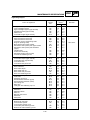
ENGINE
Item
Standard
Limit
Cylinder head:
Warp limit
•••
0.03 mm
Cylinder:
Bore size
Measuring point
95.00 95.01 mm
40 mm
95.1 mm
•••
Chain drive (left & right)
25.000 25.021 mm
24.96 24.98 mm
0.020 0.061 mm
•••
•••
•••
•••
39.112 39.212 mm
#1: 32.093 32.193 mm
#2: 32,127 32.227 mm
7.162 mm
39.145 39.245 mm
32.200 32.300 mm
7.195 mm
•••
39.012 mm
#1: 31.993 mm
#2: 32.027 mm
7.012 mm
39.045 mm
32.100 mm
7.045 mm
0.03 mm
Camshaft:
Drive method
Cam cap inside diameter
Camshaft outside diameter
Shaft-to-cap clearance
Cam dimensions:
Intake
Exhaust
Camshaft runout limit
“A”
“B”
“C”
“A”
“B”
“C”
2-4
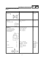
MAINTENANCE SPECIFICATIONS
Item
SPEC
Standard
Limit
Timing chain:
Timing chain type/No. of links
Timing chain adjustment method
SILENT CHAIN/98L
Automatic
•••
•••
Rocker arm/rocker arm shaft:
Bearing inside diameter
Shaft outside diameter
Arm-to-shaft clearance
14.000 mm 14.018 mm
13.985 mm 13.991 mm
0.009 mm 0.033 mm
14.036 mm
13.95 mm
0.086 mm
Valve, valve seat, valve guide:
Valve clearance (cold)
IN
EX
0.07 0.12 mm
0.12 0.17 mm
•••
•••
Valve dimensions:
Head Diameter
“A” head diameter
“B” face width
“C” seat width
“D” margin thickness
Stem outside diameter
Guide inside diameter
Stem-to-guide clearance
Face Width
IN
EX
IN
EX
IN
EX
IN
EX
IN
EX
IN
EX
IN
EX
Seat Width
47.0 47.2 mm
39.0 39.2 mm
2.1 mm
2.1 mm
1.2 1.4 mm
1.2 1.4 mm
1.1 1.5 mm
1.1 1.5 mm
7.975 7.990 mm
7.960 7.975 mm
8.000 8.012 mm
8.000 8.012 mm
0.010 0.037 mm
0.025 0.052 mm
2-5
Margin Thickness
•••
•••
•••
•••
1.8 mm
1.8 mm
0.8 mm
0.8 mm
•••
•••
•••
•••
0.08 mm
0.10 mm
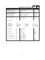
MAINTENANCE SPECIFICATIONS
Item
SPEC
Standard
Stem runout limit
Limit
•••
0.03 mm
IN
EX
1.2 1.4 mm
1.2 1.4 mm
2.0 mm
2.0 mm
IN
EX
IN
EX
IN
EX
IN
EX
44.6 mm
44.6 mm
40 mm
40 mm
160.7 N (16.4 kg)
160.7 N (16.4 kg)
•••
•••
43.5 mm
43.5 mm
•••
•••
•••
•••
2.5°/1.9 mm
2.5°/1.9 mm
IN
EX
Clockwise
Clockwise
•••
•••
Piston:
Piston to cylinder clearance
Piston size “D”
0.025 0.050 mm
94.960 94.975 mm
0.15 mm
•••
Measuring point “H”
Piston off-set
5 mm
0 mm
•••
•••
Valve seat width
Valve spring:
Free length
Set length (valve closed)
Compressed pressure (installed)
Tilt limit
Direction of winding
(top view)
2-6
MAINTENANCE SPECIFICATIONS
Item
SPEC
Standard
Limit
22.004 22.015 mm
21.991 22.000 mm
22.045
21.975
Type
Dimensions (B x T)
End gap (installed)
Side clearance (installed)
2nd ring:
Plain
1.5 3.8 mm
0.3 0.5 mm
0.04 0.08 mm
•••
•••
0.8 mm
0.1 mm
Type
Dimensions (B x T)
End gap (installed)
Side clearance
Oil ring:
Taper
1.2 3.8 mm
0.30 0.45 mm
0.03 0.07 mm
•••
•••
0.8 mm
0.1 mm
2.5 3.4 mm
0.2 0.7 mm
•••
•••
0.044 0.073 mm
1 Blue 2 Black 3 Brown
4 Green 5 Yellow
•••
•••
101.95 102.00 mm
•••
0.320 0.474 mm
•••
0.02 mm
•••
Piston pin bore inside diameter
Piston pin outside diameter
Piston rings:
Top ring:
Dimensions (B x T)
End gap (installed)
Connecting rod:
Oil clearance
Color code (corresponding size)
Crankshaft:
Crank width “A”
Runout limit “C”
Big end side clearance “D”
2-7
MAINTENANCE SPECIFICATIONS
Item
SPEC
Standard
Limit
Clutch:
Friction plate thickness
Quantity
Clutch plate thickness
Quantity
Clutch plate thickness
Quantity
Clutch spring free length
Quantity
Clutch housing thrust clearance
Clutch housing radial clearance
Clutch release method
Push rod bending limit
2.9 3.1 mm
8
2.5 2.7 mm
1
1.9 2.1 mm
7
7.2 mm
1
0.05 0.40 mm
0.010 0.044 mm
Inner push, screw push
•••
2.8
•••
0.1
•••
0.1
•••
6.5
•••
•••
•••
•••
0.5
Transmission:
Main axle deflection limit
Drive axle deflection limit
•••
•••
0.08 mm
0.08 mm
Shifter:
Shifter type
Guide bar
•••
5JN1 00
#125
#55
#5DL39-53-3
P-0M (826)
#63.8
#142.5
1.0
#17.5
0.8
0.8
0.8
3.0
1.2
#42.5
0,9
#125
4 5 mm
11 12 mm
950 1,050 r/min
32.2 33.6 kPa (242 252 mmHg)
75 85 °C
•••
•••
•••
•••
•••
•••
•••
•••
•••
•••
•••
•••
•••
•••
•••
•••
•••
•••
•••
•••
•••
•••
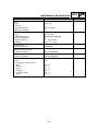
Electrical type
UC-Z6M/MITSUBISHI
0.8 A
12 kPa (0.12 kf/cm2)
•••
•••
•••
Carburetor:
I. D. mark
Main jet
Main air jet
Jet needle
Needle jet
Pilot air jet
Pilot outlet
Pilot jet
Bypass 1
Bypass 2
Bypass 3
Pilot screw
Valve seat size
Starter jet
Starter jet
Throttle valve size
Fuel level
Float height
Engine idle speed
Intake vacuum
Engine oil temperature
Fuel pump:
Type
Model/manufacturer
Consumption amperage
Output pressure
(M.J)
(M.A.J)
(J.N)
(N.J)
(P.A.J.1)
(P.A.J.2)
(P.O)
(P.J)
(B.P.1)
(B.P.2)
(B.P.3)
(P.S)
(V.S)
(G.S.1)
(G.S.2)
(TH.V)
(F.L)
(F.H)
<max>
2-8
mm
mm
mm
mm
mm
MAINTENANCE SPECIFICATIONS
Item
SPEC
Standard
Limit
Lubrication system:
Oil filter type
Oil pump type
Tip clearance “A” or “B”
Side clearance
Relief valve operating pressure
Paper type
Trochoid type
0.03 0.09 mm
0.03 0.08 mm
450 550 kPa (4.5 5.5 kg/cm2)
•••
•••
0.15 mm
0.15 mm
•••
Shaft drive:
Middle gear backlash
Final gear backlash
0.1 0.2 mm
0.1 0.2 mm
•••
•••
2-9
SPEC
MAINTENANCE SPECIFICATIONS
Item
Standard
Lubrication chart:
Needle bearing (starter)
Connecting rod big end
Main axle
Drive axle
Crankshaft
Pressure feed
Pinin drive
Splashed
Orifice
Rocker arm (EX)
Camshaft (EX)
Middle driveshaft
Rocker arm (EX)
Camshaft (IN)
Rocker arm (IN)
Rocker arm (IN)
Oil filter
Relief valve
Oil pan
2-10
Oil pump
MAINTENANCE SPECIFICATIONS
SPEC
Cylinder head tightening sequence:
Crankcase tightening sequence:
Left crankcase
Right crankcase
2-11
MAINTENANCE SPECIFICATIONS
SPEC
Tightening torques
Part to be tightened
Cylinder head
Cylinder head
Plate
Cylinder head cover
Cylinder head (exhaust pipe)
Rocker arm shaft
Camshaft sprocket cover
Tappet cover
Rocker arm shaft
(oil passage)
Stopper plate (camshaft)
Spark plug
Cylinder
Lower cylinder head cover
Upper cylinder head cover
Connecting rod
Rotor
Valve adjusting locknut
Camshaft sprocket
Timing chain tensioner
Timing chain tentioner cap
Timing chain guide
Oil pump
Oil strainer cover
Oil filter cover
Oil pump gear
Oil pump cap
Oil delivery pipe
(cylinder head)
(crankcase)
Oil drain bolt
Air filter:
Air filter cover fastener
Carburetor cover fastener
A.I.S. system:
A.I.S. system fastener
(pump and piping)
A.I.S. system pipe fastener
to engine starter
A.I.S. pump fastener
to A.I.S. bracket
Exhaust system:
Cylinder head and exhaust pipe joint
Exhaust pipe bracket
Exhaust pipe/exhaust pipe
guard fastener (rear)
Part
name
Thread
size
Q’ty
Tightening
torque
N·m
m·kg
Nut
Nut
Bolt
Screw
Stud bolt
Union
bolt
Bolt
Bolt
Bolt
M12
M10
M8
M6
M8
M16
8
2
2
4
4
2
50
35
20
4
12.5
37.5
5.0
3.5
2.0
0.4
1.25
3.75
M6
M6
M16
4
8
4
10
10
38
1.0
1.0
3.8
Bolt
M8
4
20
2.0
–
Bolt
Bolt
Screw
Nut
Nut
Nut
Bolt
Bolt
Bolt
Bolt
Bolt
Bolt
Bolt
Bolt
Bolt
Union
bolt
Union
bolt
–
M14
M6
M6
M6
M9
M16
M8
M10
M6
M6
M6
M6
M6
M6
M6
M6
M16
2
2
6
8
4
1
4
2
4
2
4
3
3
5
1
1
2
20
10
10
5
48
175
27
55
10
8
10
10
10
10
12
10
20
2.0
1.0
1.0
0.5
4.8
17.5
2.7
5.5
1.0
0.8
1.0
1.0
1.0
1.0
1.2
1.0
2.0
M10
1
20
2.0
M14
1
43
4.3
Screw
Screw
M5
M5
2
4
2
4.5
0.2
0.45
Screw
M6
4
10
1.0
Screw
M6
1
10
1.0
Screw
M5
2
8
0.8
Nut
Screw
M8
M8
4
2
20
25
2.0
2.5
Screw
M8
2
20
2.0
2-12
Remarks
Use lock
washer
MAINTENANCE SPECIFICATIONS
Part to be tightened
Exhaust pipe strap
Silencer fastener to passenger
board support
Exhaust pipe guard fastener
Crankcase (cylinder)
Crankcase (cylinder)
Crankcase
Crankcase
Bearing retainer (middle drive pinion gear)
Crankcase cover (left)
Crankcase cover (right)
Clamp
One-way clutch
Primary drive gear
Clutch spring
Clutch adjuster
Clutch boss
Push lever axle
Middle drive pinion gear
Bearing retainer (middle driven shaft)
Yoke (middle driven shaft)
Bearing housing (middle drive shaft)
Shift lever stopper
Part
name
Thread
size
Q’ty
SPEC
Tightening
torque
N·m
m·kg
Screw
M8
3
18
1.8
Screw
Screw
Stud bolt
Stud bolt
Bolt
Bolt
Bolt
Bolt
Bolt
Bolt
Bolt
Nut
M10
M6
M12
M10
M10
M6
M8
M6
M6
M6
M6
M20
2
2
8
2
3
10
3
13
11
1
8
1
47
7
24
20
38.5
10
25
10
10
10
12
110
4.7
0.7
2.4
2.0
3.85
1.0
2.5
1.0
1.0
1.0
1.2
11.0
Bolt
Nut
Nut
M6
M8
M20
6
1
1
8
12
70
0.8
1.2
7.0
Screw
Nut
Nut
Nut
Bolt
Bolt
M8
M44
M88
M14
M8
M8
1
1
1
1
4
1
12
110
110
–
25
22
1.2
11.0
11.0
–
2.5
2.2
Remarks
Use lock
washer
Use lock
washer
Stake
Stake
Stake
Use lock
washer
Guide bar stopper
Shift dram segment
Shift arm
Shift pedal adjuster
Screw
Screw
Bolt
Nut
M6
M5
M6
M6
2
1
1
2
7
4
10
10
0.7
0.4
1.0
1.0
Stator coil
Screw
M6
3
10
1.0
Pickup coil
Starter motor
Neutral switch
Ignition coil
Speed sensor
Engine bracket:
Rear fastener
Front fastener
Engine bracket fastener (front)
Engine bracket fastener (front)
Screw
Bolt
–
Screw
Bolt
M5
M6
M10
M5
M6
2
2
1
4
1
7
10
20
2.5
7
0.7
1.0
2.0
0.25
0.7
Screw
Screw
Special screw
Nut
M10
M12
M22
M12
3
1
1
4
65
110
18
85
6.5
11.0
1.8
8.5
2-13
1 of 2 has
LH thread
MAINTENANCE SPECIFICATIONS
SPEC
CHASSIS
Item
Standard
Steering system:
Steering bearing type
Front suspension:
Front fork travel
Fork spring free length
Fitting length
Collar length
Spring rate
Stroke
Angular bearing
•••
130 mm
363.3 mm
339.8 mm
150 mm
7.0 N/mm (0.71 kg/mm)
11.2 N/mm (1.14 kg/mm)
111 mm
525 mm
No
0.525 L
123 mm
Fork oil 10W or equivalent
•••
•••
•••
•••
•••
•••
•••
•••
•••
•••
•••
•••
60 mm
175 mm
162 mm
120 N/mm (12.23 kg/mm)
0 60 mm
No
•••
•••
•••
•••
•••
•••
End
•••
0 mm
radial
lateral
Cast wheel
17 MT3.50
Aluminium
•••
•••
•••
•••
•••
1.0 mm
0.5 mm
radial
lateral
Cast wheel
17 MT5.50
Aluminium
•••
•••
•••
•••
•••
1.0 mm
0.5 mm
(K1)
(K2)
(K1)
(K2)
Optional spring
Oil capacity
Oil level
Oil grade
Rear suspension:
Shock absorber travel
Spring free length
Fitting length
Spring rate
Stroke
Optional spring
Swingarm:
Free play limit
Front wheel:
Type
Rim size
Rim material
Rim runout limit
Rear wheel:
Type
Rim size
Rim material
Rim runout limit
Limit
(K1)
(K1)
2-14
MAINTENANCE SPECIFICATIONS
Item
Front brake:
Type
Disc outside diameter thickness
Disc deflection limit
Pad thickness
inner
outer
SPEC
Standard
Limit
Dual disc
298 5 mm
•••
5.5 mm
5.5 mm
•••
4.5
0.2
0.5
0.5
14.0 mm
30.2 mm
27 mm
DOT 4
•••
•••
•••
•••
Rear brake:
Type
Disc outside diameter thickeness
Disc deflection limit
Pad thickness
inner
outer
Master cylinder inside diameter
Caliper cylinder inside dimeter
Brake fluid type
Single disc
267 5 mm
•••
5.5 mm
5.5 mm
13 mm
42.85 mm
DOT 4
•••
4.5 mm
0.15 mm
0.5 mm
0.5 mm
•••
•••
Brake pedal position
Clutch lever free play (at lever end)
Throttle grip free play
43 mm
5 10 mm
3 5 mm
•••
•••
•••
Master cylinder inside diameter
Caliper cylinder inside diameter
Caliper cylinder inside diameter
Brake fluid type
2-15
mm
mm
mm
mm
MAINTENANCE SPECIFICATIONS
SPEC
Tightening torques
Thread
size
Part to be tightened
Tightening
torque
N·m
m·kg
M6
M6
M6
M5
M12
10
7
10
4
10
1.0
0.7
1.0
0.4
1.0
M8
M8
M22
–
M6
M10
M8
25
25
110
18
10
32
23
2.5
2.5
11.0
1.8
1.0
3.2
2.3
M5
M6
M8
M6
4.5
11
23
7
0.45
1.1
2.3
0.7
Front wheel:
Front brake caliper (right and left)
Front brake disc (right and left)
Front wheel axle
Front wheel axle pinch bolt
M10
M8
M18
M8
42
25
75
25
4.2
2.5
7.5
2.5
Rear wheel:
Rear brake disc
Rear brake caliper
Rear wheel axle nut
Rear wheel axle pinch bolt
Dust cover fastening screw
M8
M10
M16
M8
M5
25
35
110
22
4.5
2.5
3.5
11.0
2.2
0.45
Swingarm assembly:
Pivot shaft
Swingarm pinch bolt
Shock absorber fastener (upper)
Shock absorber fastener (lower)
Connecting arm
Relay arm
Final gear case fastening cap nut
M16
M8
M10
M10
M12
M10
M10
92
22
42
50
50
50
50
9.2
2.2
4.2
5.0
5.0
5.0
5.0
Sidestand/Shift pedal:
Sidestand
Sidestand switch
Shift rod
Ball-and-joint socket
Shift boss
Shift pedal
M8
M5
M6
M6
M6
M8
19
4.5
7
8
7
16
1.9
0.45
0.7
0.8
0.7
1.6
Front brake:
Brake hose union bolt
Front master cylinder
Front master cylinder cover
Front brake joint fastening screw
Brake hose holder fastening screw
M10
M6
–
M6
M6
28
10
2
10
10
2.8
1.0
0.2
1.0
1.0
Headlight assembly/Cowling:
Lower headlight support
Upper headlight support (right and left)
Headlight bracket (right and left)
Plastic cover
Front flasher lights (right and left)
Handlebar/Front fork assembly:
Upper bracket and inner tube
Lower bracket and inner tube
Front fork cap nut and steering shaft
Ring nut (steering shaft)
Meter bracket and upper bracket
Handlebar holder (lower) and upper bracket
Handlebar holder (lower) and handlebar
(upper)
Throttle cable
Clutch lever assembly
Handlebar weight (right and left)
Front fender fastening screw
2-16
Remarks
See “Note”
MAINTENANCE SPECIFICATIONS
Thread
size
Part to be tightened
Rear brake/Footrests:
Brake caliper torque rod
Rear brake adjuster
Rear brake pedal fastening screw (special)
Rear master cylinder fastening screw
Rear brake fluid reservoir fastening screw
Special screw for fastening rear brake hose
to brake caliper
Special screw for fastening rear brake
hose to master cylinder
Brake caliper bleed screw
Front footrest bracket fastening screw
(aluminium)
Front footrest bracket fastening screw
(steel)
Footrest damper fastening screw
Rear footrest fastening screw
Rear footrest bracket fastening screw
Tightening
torque
N·m
m·kg
M8
M6
M8
M6
M6
M10
25
10
16
10
7
28
2.5
1.0
1.6
1.0
0.7
2.8
M10
24
2.4
M6
M10
6
55
0.6
5.5
M8
23
2.3
M5
M6
M8
4
7
23
0.4
0.7
2.3
Rear lights/Rear fender/Panel assembly:
Side panel fastening screw
Battery receptacle fastening screws
Battery receptacle cover fastening screws
Plastic rear fender fastening screws
Plastic license bracket fastening screws
Rear fender cover fastening screw
(aluminium)
Seat lock fastening screw
Rear flasher lights (right and left)
Tail light fastening screw
M6
M6
M6
M6
M6
7
7
7
7
7
0.7
0.7
0.7
0.7
0.7
M8
M6
M12
M6
23
7
10
7
2.3
0.7
1.0
0.7
Fuel tank:
Fastening screw (front)
Fastening screw (rear)
Bracket fastening screw (rear)
Tank cap fastening screw
Tank cover fastening screw (aluminium)
Fuel cock fastening screw
Fuel sender fastening screw
M6
M6
M6
M5
M5
M6
M6
10
10
7
6
4
7
7
1.0
1.0
0.7
0.6
0.4
0.7
0.7
SPEC
Remarks
NOTE:
1. First, tighten the ring nut approximately 52 Nm (5.2 m·kg) by using the torque wrench, then loosen the
ring nut completely.
2. Retighten the ring nut to specification.
2-17
MAINTENANCE SPECIFICATIONS
SPEC
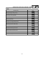
ELECTRICAL
Item
Standard
Limit
Voltage:
12 V
•••
Ignition system:
Ignition timing (B.T.D.C.)
Advancer type
10° at 1,000 r/min
Digital type
•••
•••
T.C.I.:
Pickup coil resistance/color
T.C.I. unit model/manufacturer
189 231 Ω at 20 °C / Gray–Black
J4T101/MITSUBISHI
•••
•••
Ignition coil:
Model/manufacturer
Primary winding resistance
Secondary winding resistance
F6T507/MITSUBISHI
3.57 4.83 Ω at 20 °C
10.7 14.5 kΩ at 20 °C
•••
•••
•••
Spark plug cap:
Type
Resistance
Resin type
10 kΩ
•••
•••
Charging system:
Type
Model/manufacturer
Nominal output
Stator coil resistance/color
A.C. magneto
F4T654/MITSUBISHI
14V 350W at 5,000 r/min
0.36 0.44 Ω at 20 °C / White–White
•••
•••
•••
•••
Voltage regulator:
Type
Model/manufacturer
No load regulated voltage
Semi-conductor, short-circuit type
SH650D-11/SHINDENGEN
14.1 14.9 V
•••
•••
•••
Rectifier:
Model/manufacturer
Capacity
Withstand voltage
SH650D-11/SHINDENGEN
18 A
200 V
•••
•••
•••
Battery:
Specific gravity
1.320
•••
Constant mesh type
•••
SM-13/MITSUBA
0.6 kW
0.026 0.034 Ω at 20 °C
10 mm
7.65 10,01 N (780 1021 g)
28 mm
0.7 mm
•••
•••
•••
5 mm
•••
27 mm
•••
MS5F-421/JIDECO
180 A
•••
•••
Electric starter system:
Type
Starter motor:
Model/manufacturer
Output
Armature coil resistance
Brush overall length
Brush spring pressure
Commutator diameter
Mica undercut
Starter relay:
Model/manufacturer
Amperage rating
2-18
MAINTENANCE SPECIFICATIONS
Item
SPEC
Standard
Limit
Horn:
Type
Quantity
Model/manufacturer
Maximum amperage
Plane type
1
K80 L-12V/LEB
3A
•••
•••
•••
•••
Flasher relay:
Type
Model/manufacturer
Self cancelling device
Flasher frequency
Wattage
Semi-transistor
FB222M/NIPPONDENSO
No
75 95 cycle/min
10 W 2 + 3.4 W
•••
•••
•••
•••
•••
Oil level gauge:
Model/manufacturer
5EL/DENSO
•••
Starting circuit cut-off relay:
Model/manufacturer
G8R-30Y-B/OMRON
•••
Fuel pump relay:
Model/manufacturer
G8R-30Y-B/OMRON
•••
Circuit breaker:
Type
Amperage for individual circuit:
Main
Back up
Ignition
Headlight
Carburetor heater
Signals
Fuse
30 A 1
5A1
10 A 1
15 A 1
15 A 1
10 A 1
2-19
GENERAL TORQUE SPECIFICATIONS/
CONVERSION TABLE
SPEC
EB202001
EAS00028
GENERAL TORQUE SPECIFICATIONS
CONVERSION TABLE
This chart specifies torque for standard fasteners
with standard I.S.O. pitch threads. Torque specifications for special components or assemblies are
provided for each chapter of this manual. To avoid
warpage, tighten multi-fastener assemblies in a
crisscross fashion, in progressive stages, until the
specified torque is reached. Unless otherwise
specified, torque specifications require clean, dry
threads. Components should be at room temperature.
All specification data in this manual are listed in SI
and METRIC UNITS. Use this table to convert
METRIC unit data to IMPERIAL unit data.
Ex.
METRIC
MULTIPLIER
IMP
** mm
0.03937
=
** in.
2 mm
0.03937
=
0.08 in.
CONVERSION TABLE
METRIC TO IMP
Known
A: Distance between flats
B: Outside thread diameter
A
(nut)
B
(Bolt)
m·kg
10 mm
6 mm
6
0.6
12 mm
8 mm
15
1.5
14 mm
10 mm
30
3.0
17 mm
12 mm
55
5.5
19 mm
14 mm
85
8.5
22 mm
16 mm
130
13.0
2-20
Result
Torque
m·kg
m·kg
cm·kg
cm·kg
7.233
86.794
0.0723
0.8679
ft·lb
in·lb
ft·lb
in·lb
Weight
kg
g
2.205
0.03527
lb
oz
Distance
km/hr
km
m
m
cm
mm
0.6214
0.6214
3.281
1.094
0.3937
0.03937
mph
mi
ft
yd
in
in
Volume/
Capacity
cc (cm3)
cc (cm3)
lt (liter)
lt (liter)
0.03527
0.06102
0.8799
0.2199
oz (IMP liq.)
cu·in
qt (IMP liq.)
gal (IMP liq.)
Miscellaneous
kg/mm
55.997
lb/in
14.2234
psi (lb/in2)
kg/cm2
Centigrade 9/5 (°C) + 32 Fahrenheit (°F)
General torque
specifications
N·m
Multiplier
LUBRICATION POINTS AND LUBRICANT TYPES
SPEC
EB203000
LUBRICATION POINTS AND LUBRICANT TYPES
ENGINE
Lubrication point
Symbol
Oil seal lips
O-ring
Bearing
Connecting rod bolt/nut
Connecting rod small end and big end
Crankshaft pin
Crankshaft journal/big end
Piston surface
Piston pin
Camshaft cam lobe/journal
Rocker arm shaft
Valve stem (IN, EX)
Valve stem end (IN, EX)
Timing chain drive gear shafts/sprokets
Oil pump rotor (inner/outer), housing
Idle gear surface
Starter idle gear
Starter idle gear shaft
Starter oneway cam
Middle drive gear
Primary driven gear
Push rod 1, 2
Transmission gear (wheel/pinion)
Shift cam
Shift fork/guide bar
Shift shaft assembly
Push rod ball
Push lever assembly
2-21
LUBRICATION POINTS AND LUBRICANT TYPES
SPEC
EB203010
CHASSIS
Lubrication point
Symbol
Steering head pipe (upper/lower), bearing
Steering head pipe, bearing cover lip
Steering head pipe, oil seal lip
Front wheel oil seal lip (right/left)
Rear wheel oil seal lip
Clutch hub fitting area
Rear brake pedal shaft
Shift pedal shaft
Sidestand bolt, sidestand sliding surface
Tube guide (throttle grip) inner surface
Brake lever pivot bolt, contact surface
Clutch lever pivot bolt, contact surface
Rear shock absorber (lower) oil seal lip
Swingarm pivot bearing inner surface
Swingarm pivot oil seal lip
Relay arm bearing, collar and oil seal
Drive shaft spline
Drive shaft dust cover
Drive shaft coupling gear oil seal
2-22
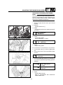
LUBRICATION DIAGRAMS
SPEC
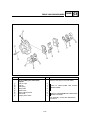
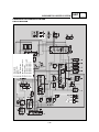
EB205000
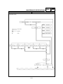
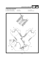
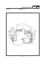
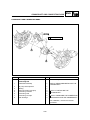
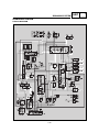
LUBRICATION DIAGRAMS
1 Rocker arm shaft (intake)
2 Rocker arm shaft (exhaust)
3 Oil filter
4 Oil pump
5 Drive axle
6 Middle drive shaft
2-23
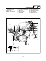
LUBRICATION DIAGRAMS
1 Oil pump
2 Releaf valve
3 Oil filter
4 Middle drive shaft
2-24
SPEC
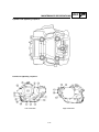
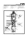
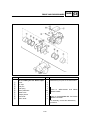
LUBRICATION DIAGRAMS
1 Camshaft
2 Crankshaft
3 Main axle
4 Middle drive shaft
5 Drive axle
6 Connecting rod big end
2-25
SPEC
CABLE ROUTING
SPEC
EB206000
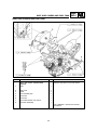
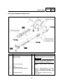
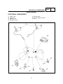
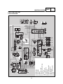
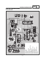
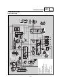
CABLE ROUTING
1
2
3
4
5
6
7
8
9
0
q
w
e
r
Relays group
Flasher relay
Speed sensor
Sidestand switch
Fuel drain hose
Engine earth
Neutral switch
Carburetor heater
Filler tank cap fuel drain pipe
Filler tank cap fuel drain pipe
Fuel hose (carburetor-3 way)
Handlebar switch leads (left)
Rectifier/regulator
Spark plug cap (front cilinder)
t
q 0
t
y
u
i
Throttle cables
Wireharness
Clutch cable
Front brake cable (left)
å Fix the wires of the left swicth
assy to the handlebar by means of
no. 2 plastic clamps.
∫ Fix the headlight leads to the
clamp.
9
2
y∫
wå
e
8
u
i
r
7
2-26
6
5
4
3
1
CABLE ROUTING
o Brake cable
d
f
g
h
j
(front master cylinder)
p Thermo swicth
a Rubber cap for front wiring
connections
s Horn
k
l
;
z
x
Front brake hose (right)
A.I.S. pipe to the front cylinder
Starter motor
Starter motor lead
Oil level gauge
SPEC
Rear brake hose
Brake fluid reservoir hose
Ignition coil (rear cylinder)
Starter relay assy
Depression fuel cock
.
o
ç;
∂,
z
x
c
p
çm
a
s
v
l
n
b
f
k
j
2-27
h
g
d
CABLE ROUTING
c
v
b
n
m Ignition coil (front cylinder)
, Handlebar switch leads (right)
. Throttle cables
Spark plug cap (rear cylinder)
A.I.S. pipe to the rear cylinder
A.I.S. system
Throttle position sensor (TPS)
SPEC
ç Check that the wires of the ignition coil do not remain tensioned.
∂ Fix the wires of the right switch
assy to the handlebar by means of
no. 1 plastic clamp.
.
o
ç;
∂,
z
x
c
p
çm
a
s
v
l
n
b
f
k
j
2-28
h
g
d
CABLE ROUTING
/ Rubber cap for front wiring
!
@
#
$
%
connections
Spark plug lead (front)
Throttle cable
Depression fuel cock
Battery
Fuel hose
^
&
*
(
)
Q
SPEC
W
E
R
T
Spark plug lead (rear)
Battery positive (+) terminal
Fuse box
Battery negative (-) terminal
Igniter unit
Fuel filter
Fuel pump
Fuel sender
Air intake pipe (A.I.S. system)
Anti-theft alarm connectors
´ Position the spark plug wire of
the rear cylinder below the fuel
hose.
/
!
R
@
E
#
W
%
$
Q
)
(
&
*
T
2-29
^
´
SPEC
INSP
ADJ
3
INSP
ADJ
CHAPTER 3.
PERIODIC INSPECTIONS AND ADJUSTMENTS
INTRODUCTION..........................................................................................................3-1
PERIODIC MAINTENANCE/LUBRICATION INTERVALS ........................................3-1
SEAT, SIDE COVERS AND FUEL TANK ....................................................................3-3
REMOVAL ............................................................................................................3-3
INSTALLATION ....................................................................................................3-3
ENGINE ........................................................................................................................3-4
ADJUSTING THE VALVE CLEARANCE ..............................................................3-4
SYNCHRONIZING THE CARBURETORS ..........................................................3-7
ADJUSTING THE ENGINE IDLING SPEED ........................................................3-9
ADJUSTING THE THROTTLE CABLE FREE PLAY ..........................................3-10
CHECKING THE SPARK PLUGS ......................................................................3-11
CHECKING THE IGNITION TIMING ..................................................................3-12
MEASURING THE COMPRESSION PRESSURE ............................................3-13
CHECKING THE ENGINE OIL LEVEL ..............................................................3-15
CHANGING THE ENGINE OIL ..........................................................................3-16
ADJUSTING THE CLUTCH CABLE FREE PLAY ..............................................3-17
CLEANING THE AIR FILTER ELEMENT............................................................3-18
CHECKING THE CARBURETOR JOINT AND INTAKE MANIFOLD..................3-19
CHECKING THE BREATHER HOSE ................................................................3-20
CHECKING THE EXHAUST SYSTEM ..............................................................3-20
CHASSIS ....................................................................................................................3-21
ADJUSTING THE FRONT BRAKE ....................................................................3-21
ADJUSTING THE REAR BRAKE ......................................................................3-22
CHECKING THE BRAKE FLUID LEVEL ............................................................3-23
CHECKING THE BRAKE HOSES ......................................................................3-24
BLEEDING THE HYDRAULIC BRAKE SYSTEM ..............................................3-24
ADJUSTING THE SHIFT PEDAL ......................................................................3-26
CHECKING THE FINAL DRIVE OIL LEVEL ......................................................3-27
CHANGING THE FINAL DRIVE OIL ..................................................................3-27
CHECKING AND ADJUSTING THE STEERING HEAD ....................................3-28
CHECKING THE FRONT FORK ........................................................................3-30
ADJUSTING THE FRONT FORK LEGS ............................................................3-31
ADJUSTING THE REAR SHOCK ABSORBER ASSEMBLY ..............................3-32
CHECKING THE TIRES......................................................................................3-33
CHECKING THE WHEELS ................................................................................3-35
CHECKING AND LUBRICATING THE CABLES ................................................3-36
LUBRICATING THE LEVERS AND PEDALS ....................................................3-36
LUBRICATING THE SIDESTAND ......................................................................3-36
INSP
ADJ
ELECTRICAL SYSTEM ............................................................................................3-37
CHECKING AND CHARGING THE BATTERY ..................................................3-37
CHECKING THE FUSES ....................................................................................3-43
REPLACING THE HEADLIGHT BULB ..............................................................3-44
ADJUSTING THE HEADLIGHT BEAM ..............................................................3-46
INTRODUCTION/PERIODIC MAINTENANCE/
LUBRICATION INTERVALS
INSP
ADJ
EB300000
PERIODIC INSPECTIONS AND ADJUSTMENTS
INTRODUCTION
This chapter includes all information necessary to perform recommended inspections and adjustments.
These preventive maintenance procedures, if followed, will ensure more reliable vehicle operation and a
longer service life. The need for costly overhaul work will be greatly reduced. This information applies to
vehicles already in service as well as to new vehicles that are being prepared for sale. All service technicians should be familiar with this entire chapter.
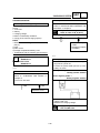
PERIODIC MAINTENANCE/LUBRICATION INTERVALS
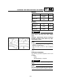
ODOMETER READING (x 1,000 km)
N0.
ITEM
CHECK OR MAINTENANCE JOB
1
*
Fuel
line
• Check fuel hoses and vacuum hose
• for cracks or damage.
2
*
Fuel filter
• Check condition.
Spurk plugs
• Check condition.
• Clean and regap.
3
1
10
20
30
40
✓
✓
✓
✓
✓
✓
4
*
5
Valves
• Check valve clearance.
• Adjust.
✓
• Clean.
✓
Air filter element
6
7
Clutch
*
Front brake
9
*
*
Rear brake
✓
✓
✓
• Check operation,fluid level and vehicle
• for fluid leakeage. (See NOTE)
✓
✓
✓
✓
✓
✓
Whenever worm to the limit
• Check operation, fluid level and vehicle for fluid
• leakage. (See NOTE)
✓
✓
✓
✓
✓
• Replace brake pads.
Whenever worm to the limit
• Check for cracks or damage.
✓
✓
✓
✓
✓
✓
Brake hoses
Every 4 years
✓
✓
✓
✓
✓
✓
✓
✓
• Check bearing for looseness or damage.
✓
✓
✓
✓
• Check operation and for excessive play.
✓
✓
✓
✓
Wheels
• Check runout and for damage.
11
*
Tires
•
•
•
•
12
*
Wheel bearings
Check tread depth and for damage.
Replace if necessary.
Check air pressure.
Correct if necessary.
Swingarm
• Lubrificate with lithium-soap-based grease.
• Check bearing play and steering for roughness.
Every 50,000 km
✓
✓
✓
✓
✓
*
Steering bearings
*
Chassis
fasteners
• Make sure that all nuts, bolts and screws are properly
titightened.ghtened.
✓
✓
✓
✓
✓
Sidestand
• Check operation.
• Lubricate.
✓
✓
✓
✓
✓
✓
✓
✓
✓
✓
✓
✓
✓
✓
• Lubrificate with lithium-soap-based grease.
15
✓
✓
*
14
✓
✓
10
*
✓
✓
• Replace. (See NOTE)
13
✓
✓
• Check operation.
• Adjust.
• Replace brake pads.
8
✓
✓
• Replace.
✓
✓
✓
• Replace.
Annual
check
16
17
*
Sidestand
switch
• Check operation and for oil leakage.
18
*
Front fork
• Check operation and for oil leakage.
Every 20,000 km
✓
3-1
INTRODUCTION/PERIODIC MAINTENANCE/
LUBRICATION INTERVALS
INSP
ADJ
ODOMETER READING (x 1,000 km)
N0.
19
20
ITEM
CHECK OR MAINTENANCE JOB
*
Rear shock
absorber
assembly
*
Rear suspension
• Check operation.
relay arm and
connecting
arm pivoting
• Lubricate with lithium-soap-based grease.
points
1
• Check operation and shock absorber for oil leakage.
•
10
20
30
40
✓
✓
✓
✓
✓
✓
✓
✓
✓
Annual
check
✓
Carburators
• Check starter (choke) operation.
• Adjust engine idling speed and synchronization.
✓
✓
✓
✓
✓
✓
22
Engine oil
• Change.
✓
✓
✓
✓
✓
✓
23
Engine oil filter
element
• Replace.
✓
24
Final gear oil
25
Moving parts
and cables
• Lubricate.
✓
✓
✓
✓
✓
✓
✓
✓
✓
✓
✓
✓
✓
✓
✓
21
*
• Check oil level and vehicle for oil leakage.
✓
• Change.
✓
26
*
Air induction
system
• Check the air cut valve and reed valve for
• damage.
• Replace the entire air induction system if
• necessary.
27
*
Lights, signals
and switches
• Check operation.
• Adjust headlight beam.
✓
✓
✓
✓
✓
✓
✓
* Items marked with an asterisk should be performed by a Yamaha dealer as they require special tools,
data and technical skills.
NOTE:
• The annual checks must be performed every year, except if a kilometer-based maintenance is performed instead.
• From 50,000 km, repeat the maintenance intervals starting from 10,000 km.
• The air filter needs more frequent service if you are riding in unusually wet or dusty areas.
• Hydraulic brake system:
• Check the brake fluid level regularly and fill as required.
• Replace the oil seals on the inner parts of the master cylinder and caliper cylinder every two years.
• Replace the brake hoses every four years or if cracked or damaged.
3-2
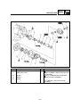
SEAT, SIDE COVERS AND FUEL TANK
INSP
ADJ
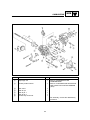
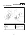
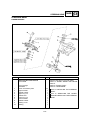
SEAT, SIDE COVERS AND FUEL TANK
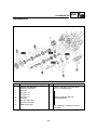
Order
Job name/Part name
Q’ty
Remarks
Remove the parts in the order below.
1
Seat, side covers and fuel tank
removal
Seat
1
2
3
4
5
6
7
8
Side cover
Panel
Fuel overflow pipe
Fuel hose
Fuel hose
Fuel meter sender unit couper
Fuel tank assembly
2
2
2
1
1
1
1
For installation, reverse the removal
procedure.
3-3
ADJUSTING THE VALVE CLEARANCE
INSP
ADJ
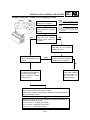
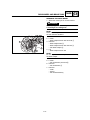
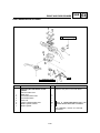
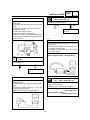
EASB0045
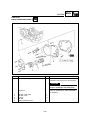
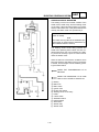
ENGINE
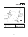
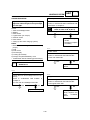
ADJUSTING THE VALVE CLEARANCE
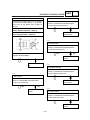
The following procedure applies to all of the
valves.
NOTE:
• Valve clearance adjustment should be made on
a cold engine, at room temperature.
• When the valve clearance is to be measured or
adjusted, the piston must be at top dead center
(TDC) on the compression stroke.
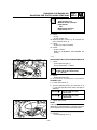
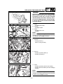
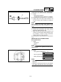
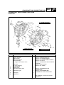
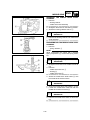
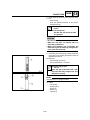
1. Remove:
• seat
• fuel tank
Refer to "SEAT, SIDE COVERS AND FUEL
TANK".
2. Disconnect:
• spark plug caps
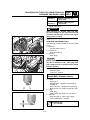
3. Remove:
• spark plugs
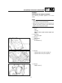
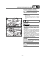
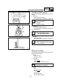
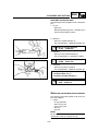
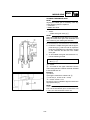
4. Remove:
• air intake box 1
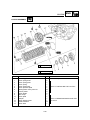
5. Remove:
• cylinder head cover (rear cylinder) 1
• cylinder head cover (front cylinder)
6. Remove:
• tappet covers 1
3-4
ADJUSTING THE VALVE CLEARANCE
INSP
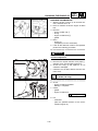
ADJ
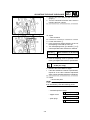
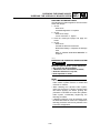
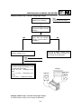
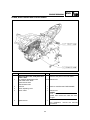
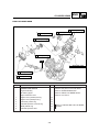
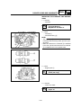
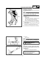
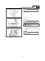
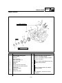
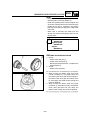
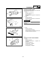
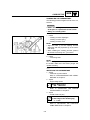
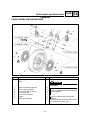
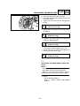
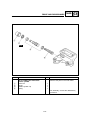
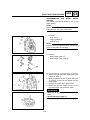
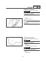
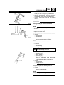
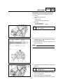
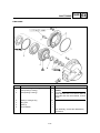
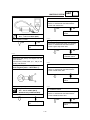
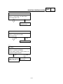
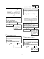
7. Remove:
• camshaft sprocket cover (rear cylinder) 1
• camshaft sprocket cover (front cylinder)
8. Remove:
• timing plug 1
• straight plug 2
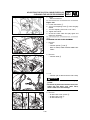
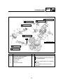
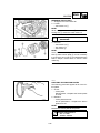
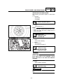
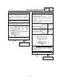
9. Measure:
• valve clearance
Out of specification → Adjust.
Valve clearance (cold):
Intake valve:
0.07 ~ 0.12 mm
Exhaust valve:
0.12 0.17 mm
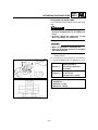
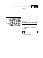
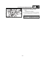
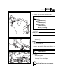
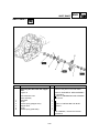
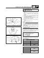
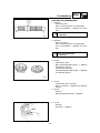
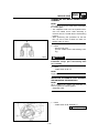
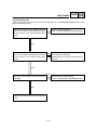
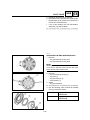
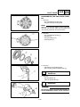
▼▼▼▼▼▼▼▼▼▼▼▼▼▼▼▼▼▼▼▼▼▼▼▼▼▼▼▼
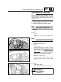
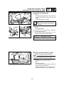
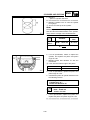
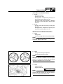
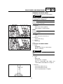
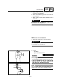
A
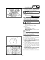
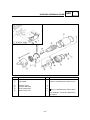
a. Turn the crankshaft counterclockwise.
b. When the piston is at TDC on the compression stroke, align either the camshaft sprocket plate hole a with the stationary pointer b
on the cylinder head. When the camshaft
sprocket plate hole or camshaft sprocket
punch mark is aligned with the stationary
pointer, the piston is at top dead center (TDC).
c. Align the TDC mark c on the generator rotor
with the stationary pointer d on the crankcase.
[A] Rear cylinder ("TI" mark)
[B] Front cylinder ("I" mark)
B
3-5
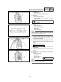
ADJUSTING THE VALVE CLEARANCE
INSP
ADJ
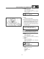
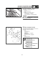
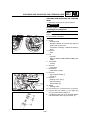
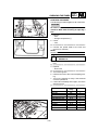
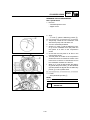
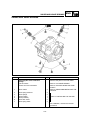
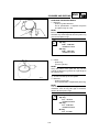
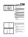
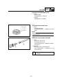
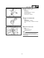
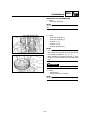
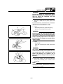
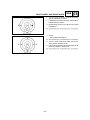
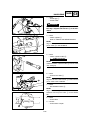
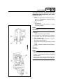
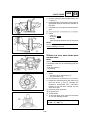
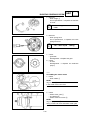
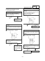
d. Measure the valve clearance with a thickness
gauge 1.
e. Turn the crankshaft crockwise 290° and then
measure the front cylinder.
▲▲▲▲▲▲▲▲▲▲▲▲▲▲▲▲▲▲▲▲▲▲▲▲▲▲▲▲▲
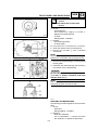
10. Adjust:
• valve clearance
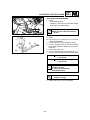
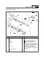
▼▼▼▼▼▼▼▼▼▼▼▼▼▼▼▼▼▼▼▼▼▼▼▼▼▼▼▼
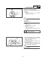
a. Loosen the locknut 1.
b. Insert a thickness gauge between the end of
the adjusting screw and the valve tip.
c. Turn the adjusting screw 2 in direction a or b
until the specified valve clearance is obtained.
Direction a
Valve clearance is decreased.
Direction b
Valve clearance is increased.
d. Hold the adjusting screw to prevent it from
moving and tighten the locknut to specification.
Locknut:
27 Nm (2.7 m•kg)
e. Measure the valve clearance again.
f. If the valve clearance is still out of specification,
repeat all of the valve clearance adjustment
steps until the specified clearance is obtained.
▲▲▲▲▲▲▲▲▲▲▲▲▲▲▲▲▲▲▲▲▲▲▲▲▲▲▲▲▲
11. Install:
• all removed parts
NOTE:
Install all removed parts in the reverse order of
their disassembly. Note the following points.
• camshaft sprocket covers
10 Nm (1.0 m•kg)
• tappet covers
10 Nm (1.0 m•kg)
• spark plugs
20 Nm (2.0 m•kg)
3-6
SYNCHRONIZING THE CARBURETORS
INSP
ADJ
EASB0002
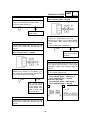
SYNCHRONIZING THE CARBURETORS
NOTE:
Prior to synchronizing the carburetors, the valve
clearance and the engine idling speed should be
properly adjusted and the ignition timing should
be checked.
1. Start the engine and let it warm up for several
minutes, then stop the engine.
2. Stand the motorcycle on a level surface.
NOTE:
Place the motorcycle on a suitable stand.
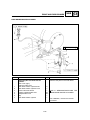
3. Remove:
• seat
4. Lift:
• fuel tank
Refer to "SEAT, SIDE COVERS AND FUEL
TANK".
NOTE:
Do not disconnect the fuel hoses.
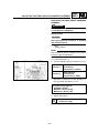
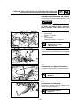
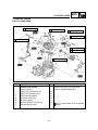
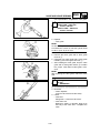
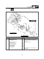
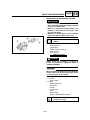
5. Remove:
• carburator side covers 4
6. Remove:
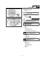
• A.I.S. hose 1
Connect vacuum hose 3 to the A.I.S. system hose connection on front cylinder n. #2.
Start the engine and fold up the fuel cock
vacuum hose 2 on rear cylinder n. #1. Fix
the fuel cock vacuum hose by means of a
plastic clamp to keep the fuel cock open.
7. Remove:
• fuel cock vacuum hose 2
Connect the other vacuum hose 3 to the
fuel cock vacuum hose on rear cylinder
n. #1.
1
8. Install:
• engine tachometer 5
(to the spark plug lead of rear cylinder #1)
Vacuum gauge:
90890-03094
Engine tachometer:
90890-03113
3-7
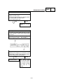
SYNCHRONIZING THE CARBURETORS
INSP
ADJ
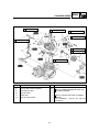
9. Check:
• engine idling speed
Out of specification → Adjust.
Refer to "ADJUSTING THE ENGINE
IDLING SPEED".
Engine idling speed:
950 ~ 1,050 r/min
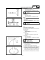
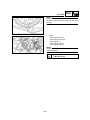
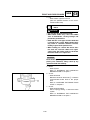
10. Adjust:
• carburetor synchronization
▼▼▼▼▼▼▼▼▼▼▼▼▼▼▼▼▼▼▼▼▼▼▼▼▼▼▼▼▼▼▼▼▼▼▼▼
a. Synchronize carburetor #1 to carburetor #2 by
turning the synchronizing screw 1 in either
direction until both gauges read the same.
b. Rev the engine two or three times, each time
for less than a second, and check the synchronization again.
Vacuum pressure at idle speed:
32.2 33.6 kPa (242 ~ 252 mmHg)
NOTE:
The difference between the two carburetors
should not exceed 1.33 kPa (10 mmHg).
▲▲▲▲▲▲▲▲▲▲▲▲▲▲▲▲▲▲▲▲▲▲▲▲▲▲▲▲▲
11. Check:
• engine idling speed
Out of specification → Adjust.
12. Stop the engine and remove the measuring
equipment.
13. Adjust:
• throttle cable free play
Refer to "ADJUSTING THE THROTTLE
CABLE FREE PLAY".
Throttle cable free play
(at the flange
of the throttle grip)
3 5 mm
14. Install:
• fuel cock vacuum hose
• A.I.S. hose
• carburator covers
• fuel tank
• seat
3-8
ADJUSTING THE ENGINE IDLING SPEED
INSP
ADJ
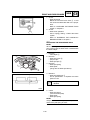
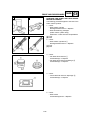
EAS00054
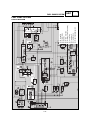
ADJUSTING THE ENGINE IDLING SPEED
NOTE:
Prior to adjusting the engine idling speed, the carburetor synchronization should be adjusted properly, the air filter should be clean, and the engine
should have adequate compression.
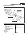
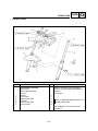
2
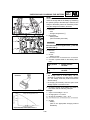
1. Start the engine and let it warm up for several
minutes.
2. Remove:
• cylinder head cover 1
3. Install:
• engine tachometer (to the spark plug lead 2
of cyl. #1)
1
Engine tachometer:
90890-03113
4. Check:
• engine idling speed
Out of specification → Adjust.
Engine idling speed:
950 ~ 1,050 r/min
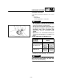
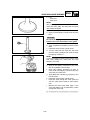
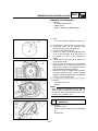
5. Adjust:
• engine idling speed
▼▼▼▼▼▼▼▼▼▼▼▼▼▼▼▼▼▼▼▼▼▼▼▼▼▼▼▼▼
a. Turn the pilot screw 1 in until it is lightly seated.
b. Turn the pilot screw out the specified number
of turns.
Pilot screw:
3 turns out
c. Turn the throttle stop screw 2 in direction a
or b until the specified engine idling speed is
obtained.
Direction a
Engine idling speed is
increased.
Direction b
Engine idling speed is
decreased.
▲▲▲▲▲▲▲▲▲▲▲▲▲▲▲▲▲▲▲▲▲▲▲▲▲▲▲▲▲
6. Adjust:
• throttle cable free play
Refer to "ADJUSTING THE THROTTLE
CABLE FREE PLAY".
3-9
ADJUSTING THE THROTTLE CABLE FREE PLAY
INSP
ADJ
EASB0003
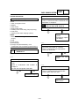
ADJUSTING THE THROTTLE CABLE FREE
PLAY
NOTE:
Prior to adjusting the throttle cable free play, the
engine idling speed should be adjusted.
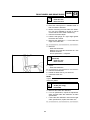
1. Check:
• throttle cable free play a
Out of specification → Adjust.
Throttle cable free play
(at the flange
of the throttle grip)
3 5 mm
2. Remove:
• carburetor cover (left)
3. Adjust:
• throttle cable free play
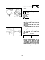
▼▼▼▼▼▼▼▼▼▼▼▼▼▼▼▼▼▼▼▼▼▼▼▼▼▼▼▼▼
NOTE:
When the motorcycle is accelerating, the accelerator cable 1 is pulled.
Carburetor side
a. Loosen the locknut 2 on the accelerator
cable.
b. Turn the adjusting nut 3 in direction a or b
until the specified throttle cable free play is
obtained.
Direction a
Throttle cable free play
is decreased.
Direction b
Throttle cable free play
is increased.
c. Tighten the locknuts.
NOTE:
If the specified throttle cable free play cannot be
obtained on the carburetor side of the cable, use
the adjusting nut on the handlebar side.
Handlebar side
a. Loosen the locknut 1.
b. Turn the adjusting nut 2 in direction a or b
until the specified throttle cable free play is
obtained.
1
b
a
2
3-10
ADJUSTING THE THROTTLE CABLE FREE PLAY/
CHECKING THE SPARK PLUGS
INSP
ADJ
Direction a
Throttle cable free play
is increased.
Direction b
Throttle cable free play
is decreased.
c. Tighten the locknut.
WARNING
After adjusting the throttle cable free play,
turn the handlebar to the right and to the left
to ensure that this does not cause the engine
idling speed to change.
1
2
▲▲▲▲▲▲▲▲▲▲▲▲▲▲▲▲▲▲▲▲▲▲▲▲▲▲▲▲▲
EASB0004
CHECKING THE SPARK PLUGS
The following procedure applies to all of the spark
plugs.
1. Remove:
• cylinder head covers 1
2. Disconnect:
• spark plug caps 2
3. Remove:
• spark plugs
CAUTION:
Before removing the spark plugs, blow away
any dirt accumulated in the spark plug wells
with compressed air to prevent it from falling
into the cylinders.
1
2
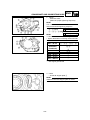
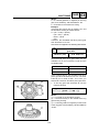
4. Check:
• spark plug type
Incorrect → Change.
Spark plug type (manufacturer)
BPR7ES (NGK) - W22EPR-U (DENSO)
5. Check:
• electrode 1
Damage/wear → Replace the spark plug.
• insulator 2
Abnormal color → Replace the spark plug.
Normal color is a medium-to-light tan color.
6. Clean:
• spark plug
(with a spark plug cleaner or wire brush)
7. Measure:
• spark plug gap a (with a wire gauge)
Out of specification → Regap.
Spark plug gap
0.7 ~ 0.8 mm
3-11
INSP
ADJ
CHECKING THE SPARK PLUGS/
CHECKING THE IGNITION TIMING
8. Install:
• spark plugs
20 Nm (2.0 m•kg)
NOTE:
Before installing the spark plug, clean the spark
plug and gasket surface.
9. Connect:
• spark plug caps
10. Install:
• cylinder head covers
EAS00064
CHECKING THE IGNITION TIMING
1
NOTE:
Prior to checking the ignition timing, check the
wiring connections of the entire ignition system.
Make sure that all connections are tight and free
of corrosion.
1. Remove:
• timing plug 1
2. Install:
• timing light 2
• engine tachometer 3 (to the spark plug lead
of cylinder #1)
2
3
Timing light:
90890-03141
Engine tachometer:
90890-03113
3. Check:
• ignition timing
▼▼▼▼▼▼▼▼▼▼▼▼▼▼▼▼▼▼▼▼▼▼▼▼▼▼▼▼▼
a. Start the engine, warm it up for several minutes, and then let it run at the specified engine
idling speed.
Engine idling speed:
950 ~ 1,050 r/min
b. Check that the stationary pointer a is within
the firing range b on the generator rotor.
Incorrect firing range → Check the ignition
system.
NOTE:
The ignition timing is not adjustable.
▲▲▲▲▲▲▲▲▲▲▲▲▲▲▲▲▲▲▲▲▲▲▲▲▲▲▲▲▲
4. Install:
• timing plug
3-12
MEASURING THE COMPRESSION PRESSURE
INSP
ADJ
EAS00065
MEASURING THE COMPRESSION PRESSURE
The following procedure applies to all of the cylinders.
NOTE:
Insufficient compression pressure will result in a
loss of performance.
1. Check:
• valve clearance
Out of specification → Adjust.
Refer to "ADJUSTING THE VALVE CLEARANCE".
2. Start the engine, warm it up for several minutes, and then turn it off.
3. Disconnect:
• spark plug cap
4. Remove:
• spark plug
CAUTION:
Before removing the spark plugs, use compressed air to blow away any dirt accumulated in the spark plug wells to prevent it from
falling into the cylinders.
1
5. Install:
• compression gauge 1
Compression gauge set:
90890-03081
6. Measure:
• compression pressure
Above the maximum pressure → Inspect the
cylinder head, valve surfaces, and piston
crown for carbon deposits.
Below the minimum pressure → Squirt a few
drops of oil into the affected cylinder and
measure again.
• Refer to the following table.
3-13
MEASURING THE COMPRESSION PRESSURE
INSP
ADJ
Compression pressure
(with oil applied in the cylinder)
Reading
Diagnosis
Higher
than without
oil
Piston wear or
damage → Repair
Same as
without oil
Piston ring(s), valves,
cylinder head gasket
or piston possibly
defective → Repair
Compression pressure
(at sea level)
Standard:
1,000 kPa (10 kg/cm2, 10 bar)
Minimum:
900 kPa (9 kg/cm2, 9 bar)
Maximum:
1,100 kPa (11 kg/cm2, 11 bar)
▼▼▼▼▼▼▼▼▼▼▼▼▼▼▼▼▼▼▼▼▼▼▼▼▼▼▼▼▼
a. Turn the main switch to "ON".
b. With the throttle wide open, crank the engine
until the reading on the compression gauge
stabilized.
WARNING
To prevent sparking, ground all spark plug
leads before cranking the engine.
NOTE:
The difference in compression pressure between
cylinders should not exceed 100 kPa (1 kg/cm2,
1 bar).
7. Install:
• spark plug
8. Connect:
• spark plug cap
3-14
20 Nm (2.0 m•kg)
CHECKING THE ENGINE OIL LEVEL
INSP
ADJ
EAS00069
CHECKING THE ENGINE OIL LEVEL
1. Stand the motorcycle on a level surface.
NOTE:
• Place the motorcycle on a suitable stand.
• Make sure that the motorcycle is upright.
2. Let the engine idle for a few minutes.
3. Check:
• engine oil level
• The engine oil level should be between the
minimum level marks a and maximum level
marks b.
Below the minimum level mark → Add the
recommended engine oil to the proper level.
b
Recommended engine oil
Refer to the chart for the engine
oil grade which is best suited for
certain atmospheric temperatures.
API standard
SE or higher grade
ACEA standard
G4 or G5
a
CAUTION:
• Engine oil also lubricates the clutch and the
wrong oil types or additives could cause
clutch slippage. Therefore, do not add any
chemical additives or use engine oils with a
grade of CD a or higher and do not use oils
labeled "ENERGY CONSERVING II" b or
higher.
• Do not allow foreign materials to enter the
crankcase.
4. Start the engine, warm it up for several minutes, and then turn it off.
5. Check the engine oil level again.
NOTE:
Before checking the engine oil level, wait a few
minutes until the oil has settled.
3-15
CHANGING THE ENGINE OIL
INSP
ADJ
EASB0005
CHANGING THE ENGINE OIL
1. Start the engine, warm it up for several minutes, and then turn it off.
2. Place a container under the engine oil drain
bolt.
3. Remove:
• engine oil filler cap 1
• O-ring
• engine oil drain bolt 2
• gasket
4. Drain:
• engine oil
(completely from the crankcase)
5. If the oil filter element is also to be replaced,
perform the following procedure.
▼▼▼▼▼▼▼▼▼▼▼▼▼▼▼▼▼▼▼▼▼▼▼▼▼▼▼▼▼
WARNING
Oil filter element replacement should be made
at room temperature.
a. Remove the oil filter element cover plate 1,
element cover 2 and oil filter element 3.
b. Check the O-ring 4 and replace it if it is
cracked or damaged.
c. Install the new oil filter element and the element cover.
1
Oil filter element cover bolt
10 Nm (1.0 m•kg)
▲▲▲▲▲▲▲▲▲▲▲▲▲▲▲▲▲▲▲▲▲▲▲▲▲▲▲▲▲
6. Check:
• engine oil drain bolt gasket
Damage → Replace.
7. Install:
• gasket
• engine oil drain bolt
43 Nm (4.3 m•kg)
4
3
4
2
8. Fill:
• crankcase
(with the specified amount of the recommended engine oil)
3-16
CHANGING THE ENGINE OIL/
ADJUSTING THE CLUTCH CABLE FREE PLAY
INSP
ADJ
Quantity
Total amount: 3.6 L
Without oil filter element
replacement:
3.0 L
With oil filter element
replacement: 3.1 L
9. Install:
• O-ring
• engine oil filter cap
10. Start the engine, warm it up for several minutes, and then turn it off.
11. Check:
• engine (for engine oil leaks)
12. Check:
• engine oil level
Refer to "CHECKING THE ENGINE OIL
LEVEL".
EASB0006
ADJUSTING THE CLUTCH CABLE FREE PLAY
1. Check:
• clutch cable free play a
Out of specification → Adjust.
c
b
2
1
Clutch cable free play
(at the end of the clutch lever)
5 10 mm
a
2. Adjust:
• clutch cable free play
▼▼▼▼▼▼▼▼▼▼▼▼▼▼▼▼▼▼▼▼▼▼▼▼▼▼▼▼▼
Handlebar side
a. Loosen the locknut 1.
b. Turn the adjusting screw 2 in direction b or
c until the specified clutch cable free play is
obtained.
Direction b
Clutch cable free play
is increased.
Direction c
Clutch cable free play
is decreased.
c. Tighten the locknut.
NOTE:
If the specified clutch cable free play cannot be
obtained as described above, perform the mechanism adjustment procedure described below.
▲▲▲▲▲▲▲▲▲▲▲▲▲▲▲▲▲▲▲▲▲▲▲▲▲▲▲▲▲
3. Remove:
• clutch adjusting cover 1
1
3-17
ADJUSTING THE CLUTCH CABLE FREE PLAY/
CLEANING THE AIR FILTER ELEMENT
INSP
ADJ
4. Adjust:
• clutch mechanism
▼▼▼▼▼▼▼▼▼▼▼▼▼▼▼▼▼▼▼▼▼▼▼▼▼▼▼▼▼
Engine side
a. Loosen the locknut 1.
b. Turn in the adjusting screw 2 until it is lightly
seated.
c. Turn the adjusting screw out 1/4 of a turn.
d. Tighten the locknut.
e. Check the clutch cable free play again and
adjust it if necessary.
1 —2
▲▲▲▲▲▲▲▲▲▲▲▲▲▲▲▲▲▲▲▲▲▲▲▲▲▲▲▲▲
EASB0007
CLEANING THE AIR FILTER ELEMENT
1. Remove:
• seat
• fuel tank panels 1 and 2
Refer to "SEAT, SIDE COVERS AND FUEL
TANK".
2. Remove:
• fuel tank bolts 3
3
3
3. Lift:
• fuel tank (do not disconnect the fuel hoses)
WARNING
• Make sure that the fuel tank is securely supported.
• Do not tilt or pull the fuel tank too much, otherwise the fuel hoses may come loose,
which could cause fuel leakage.
5
4. Remove:
• air filter case cover screws 4
• air filter case cover 5
• air filter element 6
6
4
3-18
CLEANING THE AIR FILTER ELEMENT/
CHECKING THE CARBURETOR JOINT AND INTAKE MANIFOLD
INSP
ADJ
5. Clean:
• air filter element
Apply compressed air to the outer surface of
the air filter element.
6. Check:
• air filter element
Damage → Replace.
7. Install:
• air filter element
• air filter case cover
• fuel tank
• fuel tank panels
CAUTION:
Never operate the engine without the air filter
element installed. Unfiltered air will cause
rapid wear of engine parts and may damage
the engine. Operating the engine without the
air filter element will also affect the carburetor
turning, leading to poor engine performance
and possible overheating.
NOTE:
When installing the air filter element into the air filter case cover, be sure their sealing surfaces are
aligned to prevent any air leaks.
EAS00094
CHECKING THE CARBURETOR JOINT AND
INTAKE MANIFOLD
1
1. Check:
• carburetor joint 1
Cracks/damage → Replace.
Refer to "CARBURETOR" in chapter 5.
3-19
CHECKING THE BREATHER HOSE/
CHECKING THE EXHAUST SYSTEM
INSP
ADJ
EAS00098
CHECKING THE BREATHER HOSE
1. Remove:
• cylinder head cover
2. Check:
• cylinder head breather hose 1
Cracks/damage → Replace.
Loose connection → Connect properly.
1
CAUTION:
Make sure that the cylinder head breather
hose is routed correctly.
EAS00100
CHECKING THE EXHAUST SYSTEM
The following procedure applies to all of the exhaust pipes, mufflers and gaskets.
1. Check:
• exhaust pipes 1
• muffler 2
Cracks/damage → Replace.
• gaskets 3
Exhaust gas leaks → Replace.
2. Check:
• tightening torque
Exhaust pipe nut 4
20 Nm (2.0 m•kg)
Exhaust pipe bracket bolt 5
25 Nm (2.5 m•kg)
Exhaust pipe strap 6
18 Nm (1.8 m•kg)
Muffler and passenger footrest bolt 7
47 Nm (4.7 m•kg)
Exhaust pipe bolt/Rear guard
fastener 8
20 Nm (2.0 m•kg)
3-20
ADJUSTING THE FRONT BRAKE
INSP
ADJ
2
1
3
EB304001
CHASSIS
4
ADJUSTING THE FRONT BRAKE
1. Adjust:
• brake lever position
(distance a between the brake lever and
the handlebar grip)
2
a
▼▼▼▼▼▼▼▼▼▼▼▼▼▼▼▼▼▼▼▼▼▼▼▼▼▼▼▼▼
a. Turn the adjusting dial 1 while holding the
lever pushed away from the handlebar grip
1
NOTE:
Align the setting on the adjusting dial with the
arrow mark 2
Position n. 1
Maximum a
distance
Position n. 4
Minimum a
distance
WARNING
After adjusting the brake lever position, make
sure the pin on the brake lever holder is firmly inserted in the hole in the adjusting dial.
▲▲▲▲▲▲▲▲▲▲▲▲▲▲▲▲▲▲▲▲▲▲▲▲▲▲▲▲▲
WARNING
A soft or spongy feeling in the brake lever can
indicate the presence of air in the brake system. Before the vehicle is operated, the air
must be removed by bleeding the brake system. Air in the brake system will considerably
reduce braking performance and could result
in loss of control and possibly an accident.
Therefore, inspect and, if necessary, bleed the
brake system. After adjusting the brake lever
free play, make sure that there is no brake
drag.
3-21
ADJUSTING THE REAR BRAKE
INSP
ADJ
EASB0008
ADJUSTING THE REAR BRAKE
1. Check:
• brake pedal position
(distance a from the top of the rider footrest
to the top of the brake pedal)
a
Brake pedal position
(below the top of the rider footrest)
43 mm
A
Out of specification → Adjust.
2. Adjust:
▼▼▼▼▼▼▼▼▼▼▼▼▼▼▼▼▼▼▼▼▼▼▼▼▼▼▼▼▼
• brake pedal position
a. Loosen the bolt 1 of the adjusting dial 2.
b. Turn the adjusting dial 2 until the specified
brake pedal position is obtained, then tighten
the bolt 1.
c. Loosen the locknut 3.
d. Turn the adjusting bolt 4 in direction b or c
until the correct free play between brake pedal
Direction b → Brake pedal free play
is increased.
Direction c → Brake pedal free play
is decreased.
Brake pedal and master
cylinder free play:
2 - 3 mm (at the front end
of the brake pedal)
and master cylinder is obtained.
Locknut
12 Nm (1.2 m•kg)
e. Tighten the locknut 1 to specification.
3-22
CHECKING THE BRAKE FLUID LEVEL
INSP
ADJ
EAS00115
CHECKING THE BRAKE FLUID LEVEL
1. Stand the motorcycle on a level surface.
NOTE:
• Place the motorcycle on a suitable stand.
• Make sure that the motorcycle is upright.
2. Check:
• brake fluid level
Below the minimum level mark a → Add the
recommended brake fluid to the proper
level.
A
Recommended brake fluid:
DOT4
[A] Front brake
[B] Rear brake
a
WARNING
• Use only the designated brake fluid. Other
brake fluids may cause the rubber seals to
deteriorate, causing leakage and poor brake
performance.
• Refill with the same type of brake fluid that
is already in the system. Mixing brake fluids
may result in a harmful chemical reaction,
leading to poor brake performance.
• When refilling, be careful that water does
not enter the reservoir. Water will significantly lower the boiling point of the brake
fluid and could cause vapor lock.
B
a
CAUTION:
Brake fluid may damage painted surfaces and
plastic parts. Therefore, always clean up any
spilt brake fluid immediately.
NOTE:
In order to ensure a correct reading of the brake
fluid level, make sure that the top of the reservoir
is horizontal.
3-23
CHECKING THE BRAKE HOSES/
BLEEDING THE HYDRAULIC BRAKE SYSTEM
INSP
ADJ
EAS00131
CHECKING THE BRAKE HOSES
The following procedure applies to all of the brake
hoses and clamps.
1. Check:
• brake hose
Cracks/damage/wear → Replace.
2. Check:
• brake hose clamp
Loose connection → Tighten.
3. Hold the motorcycle upright and apply the
brake.
4. Check:
• brake hose
Activate the brake several times.
Brake fluid leakage → Replace the damage
hose.
Refer to "FRONT AND REAR BRAKES" in
chapter 6.
EAS00134
BLEEDING THE HYDRAULIC BRAKE SYSTEM
WARNING
Bleed the hydraulic brake system whenever:
• the system was disassembled,
• a brake hose was loosened or removed,
• the brake fluid level is very low,
• brake operation is faulty.
NOTE:
• Be careful not to spill any brake fluid or allow the
brake master cylinder reservoir or brake fluid
reservoir to overflow.
• When bleeding the hydraulic brake system,
make sure that there is always enough brake
fluid before applying the brake. Ignoring this
precaution could allow air to enter the hydraulic
brake system, considerably lengthening the
bleeding procedure.
• If bleeding is difficult, it may be necessary to let
the brake fluid settle for a few hours. Repeat the
bleeding procedure when the tiny bubbles in the
hose have disappeared.
3-24
BLEEDING THE HYDRAULIC BRAKE SYSTEM
INSP
ADJ
1. Stand the motorcycle on a level surface.
NOTE:
• Place the motorcycle on a suitable stand.
• Make sure that the motorcycle is upright.
2. Bleed:
• hydraulic brake system
▼▼▼▼▼▼▼▼▼▼▼▼▼▼▼▼▼▼▼▼▼▼▼▼▼▼▼▼▼
A
1
a. Add the recommended brake fluid to the proper level.
b. Install the diaphragm (brake master cylinder
reservoir or brake fluid reservoir).
c. Connect a clear plastic hose 1 tightly to the
bleed screw 2.
[A]: Front
[B]: Rear
d. Place the other end of the hose into a container.
e. Slowly apply the brake several times.
f. Fully squeeze the brake lever or fully depress
the brake pedal and hold it in position.
g. Loosen the bleed screw.
This will release the tension and cause the
brake lever to contact the throttle grip or the
brake pedal to fully extend.
h. Tighten the bleed screw and then release the
brake lever or brake pedal.
i. Repeat steps (e) to (h) until all of the air bubbles have disappeared from the brake fluid in
the plastic hose.
j. Tighten the bleed screw to specification.
2
B
2
Bleed screw
6 Nm (0.6 m•kg)
k. Fill the reservoir to the proper level.
Refer to "CHECKING THE BRAKE FLUID
LEVEL".
WARNING
After bleeding the hydraulic brake system,
check the brake operation.
▲▲▲▲▲▲▲▲▲▲▲▲▲▲▲▲▲▲▲▲▲▲▲▲▲▲▲▲▲
3-25
ADJUSTING THE SHIFT PEDAL/
CHECKING THE FINAL DRIVE OIL LEVEL
INSP
ADJ
EASB0009
ADJUSTING THE SHIFT PEDAL
1. Check:
• shift pedal position (distance a from the top
of the rider footrest to the top of the shift
pedal)
Out of specification → Adjust.
A
a
Shift pedal position
(below the top of the rider footrest)
45 mm
2. Adjust:
• shift pedal position
2
▼▼▼▼▼▼▼▼▼▼▼▼▼▼▼▼▼▼▼▼▼▼▼▼▼▼▼▼▼
c
a. Loosen both locknuts 1.
b. Turn the shift rod 2 in direction b or c to
obtain the correct shift pedal position.
1
1
b
Direction b → Shift pedal is raised.
Direction c → Shift pedal is lowered.
▲▲▲▲▲▲▲▲▲▲▲▲▲▲▲▲▲▲▲▲▲▲▲▲▲▲▲▲▲
EAS00144
CHECKING THE FINAL DRIVE OIL LEVEL
1. Stand the motorcycle on a level surface.
NOTE:
• Place the motorcycle on a suitable stand.
• Make sure that the motorcycle is upright.
1
2
2. Remove:
• final drive housing oil filler bolt 1
3. Check:
• final drive oil level
The final drive oil level should be to the bottom brim 2 of the filler hole.
Below the bottom brim → Add the recommended final drive oil to the proper level.
3-26
CHECKING THE FINAL DRIVE OIL LEVEL/
CHANGING THE FINAL DRIVE OIL
INSP
ADJ
Recommended final drive oil
SAE 80 hypoid gear oil
graded "GL-4", "GL-5" or "GL-6"
or
multi-purpose SAE 80W90
hypoid gear oil
4. Install:
• final drive housing oil filler bolt
23 Nm (2.3 m•kg)
EAS00145
CHANGING THE FINAL DRIVE OIL
1. Place a container under the final drive housing.
2. Remove:
• final drive housing oil filler bolt 1
• final drive housing oil drain bolt 2
Completely drain the final drive housing of
its oil.
3. Check:
• final drive housing oil drain bolt gasket
Damage → Replace.
4. Install:
• final drive housing oil drain bolt
1
3
2
23 Nm (2.3 m•kg)
5. Fill:
• final drive housing (to the bottom brim 3 of
the filler hole) (with the specified amount of
the recommended final drive oil)
Quantity
0.2 L
6. Install:
• final drive housing oil filler bolt
23 Nm (2.3 m•kg)
Refer to "CHECKING THE FINAL DRIVE OIL
LEVEL".
3-27
CHECKING AND ADJUSTING THE STEERING HEAD
INSP
ADJ
EASB0010
CHECKING AND ADJUSTING THE STEERING
HEAD
1. Stand the motorcycle on a level surface.
WARNING
Securely support the motorcycle so that there
is no danger of it falling over.
NOTE:
Place the motorcycle on a suitable stand so that
the front wheel is elevated.
2. Check:
• steering head
Grasp the bottom of the front fork legs and
gently rock the front fork.
Looseness or binding → Adjust the steering
head.
3. Remove:
• seat
4. Lift:
• fuel tank
Refer to "SEAT, SIDE COVERS AND FUEL
TANK".
5. Tilt forward:
• cowling
6. Remove:
• meter assy
7. Disconnect:
• main switch coupler
8. Remove:
• upper handle holder 1
• handle 2
9. Remove
• steering crown nut 3
• upper bracket 4
(loosen bolts 5)
10. Adjust:
• steering head
1
5
2
4
3
1
5
▼▼▼▼▼▼▼▼▼▼▼▼▼▼▼▼▼▼▼▼▼▼▼▼▼▼▼▼▼
a. Remove the lock washer 1, the upper ring
nut 2 and the rubber washer 3.
b. Loosen the lower ring nut 4 and then tighten
it to specification with a ring nut wrench 5.
3-28
CHECKING AND ADJUSTING THE STEERING HEAD
INSP
ADJ
NOTE:
Set the torque wrench at a right angle to the ring
nut wrench 5.
Ring nut wrench
90890-01403
Lower ring nut
(initial tightening torque)
52 Nm (5.2 m•kg)
c. Loosen the lower ring nut 4 completely, then
tighten it to specification.
WARNING
Do not overtighten the lower ring nut.
Lower ring nut
(final tightening torque)
18 Nm (1.8 m•kg)
d. Check the steering head for looseness or
binding by turning the front fork all the way in
both directions. If any binding is felt, remove
the lower bracket and inspect the upper and
lower bearings. Refer to "STEERING HEAD
AND HANDLEBAR" in chapter 6.
e. Install the rubber washer 3.
f. Install the upper ring nut 2.
g. Finger tighten the upper ring nut 2, then align
the slots of both ring nuts. If necessary, hold
the lower ring nut and tighten the upper ring
nut until their slots are aligned.
h. Install the lock washer 1.
NOTE:
Make sure that the lock washer tabs a sit correctly in the ring nut slots b.
▲▲▲▲▲▲▲▲▲▲▲▲▲▲▲▲▲▲▲▲▲▲▲▲▲▲▲▲▲
11. Install:
• steering crown nut
Steering crown nut
110 Nm (11.0 m•kg)
Upper bracket bolt
25 Nm (2.5 m•kg)
3-29
CHECKING AND ADJUSTING THE STEERING HEAD/
CHECKING THE FRONT FORK
INSP
ADJ
12. Install:
• handle
13. Install:
• upper handle holder
Refer to “INSTALLING THE HANDLEBAR”
in chapter 6.
Handle holder bolt
23 Nm (2.3 m•kg)
14. Connect:
• main switch coupler
15. Install:
• meter assy
Meter bracket
10 Nm (1.0 m•kg)
16. Install:
• cowling
• fuel tank
Refer to "SEAT, SIDE COVERS AND FUEL
TANK".
EAS00149
CHECKING THE FRONT FORK
1. Stand the motorcycle on a level surface.
WARNING
Securely support the motorcycle so that there
is no danger of it falling over.
2. Check:
• inner tube
Damage/scratches → Replace.
• oil seal
Oil leakage → Replace.
3. Hold the motorcycle upright and apply the
front brake.
4. Check:
• operation
Push down hard on the handlebar several
times and check if the front fork rebounds
smoothly.
Unsmooth operation → Repair.
Refer to "FRONT FORK" in chapter 6.
3-30
ADJUSTING THE FRONT FORK
INSP
ADJ
EAS00155
ADJUSTING THE FRONT FORK
The following procedure applies to both of the fork
legs.
WARNING
• Always adjust both fork legs equally, otherwise poor handling and loss of stability may
result.
• Securely support the motorcycle so that
there is no danger of it falling over.
Spring preload
CAUTION:
• Marks are provided on adjusting bolts.
• Never go beyond the maximum or minimum
adjustment positions.
1. Adjust:
• spring preload
▼▼▼▼▼▼▼▼▼▼▼▼▼▼▼▼▼▼▼▼▼▼▼▼▼▼▼▼▼
a. Turn the adjusting bolt 1 in direction a or b.
a
b
Direction a
Spring preload is
increased (suspension
is harder).
Direction b
Spring preload
is decreased
(suspension is softer).
1
Adjusting position
Standard: 5
Minimum: 7 (soft)
Maximum: 1 (hard)
▲▲▲▲▲▲▲▲▲▲▲▲▲▲▲▲▲▲▲▲▲▲▲▲▲▲▲▲▲
3-31
ADJUSTING THE REAR SHOCK ABSORBER ASSEMBLY
INSP
ADJ
EASB0011
ADJUSTING THE REAR SHOCK ABSORBER
ASSEMBLY
WARNING
Securely support the motorcycle so that there
is no danger of it falling over.
Spring preload
CAUTION:
Never go beyond the maximum or minimum
adjustment positions.
1. Adjust:
• spring preload
NOTE:
Use the special wrench included in the owner's
tool kit to make the adjustment.
▼▼▼▼▼▼▼▼▼▼▼▼▼▼▼▼▼▼▼▼▼▼▼▼▼▼▼▼▼
a. Loosen the locknut 1.
b. Turn the adjusting nut 2 in direction a or b.
Direction a
Spring preload
is increased
(suspension is harder).
Direction b
Spring preload
is decreased
(suspension is softer).
c. With each complete turn of the adjusting nut,
spring preload changes by 1.5 mm.
Preloaded spring length A:
Standard: 162 mm
Minimum: 154 mm (hard)
Maximum: 170 mm (soft)
d. Tighten the locknut.
Locknut
45 Nm (4.5 m•kg)
▲▲▲▲▲▲▲▲▲▲▲▲▲▲▲▲▲▲▲▲▲▲▲▲▲▲▲▲▲
3-32
CHECKING THE TIRES
INSP
ADJ
EAS00162
CHECKING THE TIRES
The following procedure applies to both of the
tires.
1. Measure:
• tire pressure
Out of specification → Regulate.
WARNING
• The tire pressure should only be checked
and regulated when the tire temperature
equals the ambient air temperature.
• The tire pressure and the suspension must
be adjusted according to the total weight
(including cargo, rider, passenger and
accessories) and the anticipated riding
speed.
• Operation of an overloaded motorcycle
could cause tire damage, an accident or an
injury.
NEVER OVERLOAD THE MOTORCYCLE.
Basic weight
(with oil and
full fuel tank)
Maximum load
Cold tire pressure
Up to 90 kg load*
90 kg ~
maximum load*
250.5 kg
200 kg
Front tire
Rear tire
230 kPa
250 kPa
(2.30 kg/cm2, (2.50 kg/cm2,
2.30 bar)
2.50 bar)
250 kPa
270 kPa
(2.50 kg/cm2, (2.70 kg/cm2,
2.50 bar)
2.70 bar)
* Total of cargo, rider, passenger and accessories
WARNING
It is dangerous to ride with a worn-out tire.
When the tire tread reaches the wear limit,
replace the tire immediately.
3-33
CHECKING THE TIRES
INSP
ADJ
2. Check:
• tire surfaces
Damage/wear → Replace the tire.
Minimum tire tread depth
1.6 mm
1 Tire tread depth
2 Side wall
3 Wear indicator
WARNING
A
• Do not use a tubeless tire on a wheel
designed only for tube tires to avoid tire failure and personal injury from sudden deflation.
• When using a tube tire, be sure to install the
correct tube.
• Always replace a new tube tire and a new
tube as a set.
• To avoid pinching the tube, make sure that
the wheel rim band and tube are centered in
the wheel groove.
• Patching a punctured tube is not recommended. If it is absolutely necessary to do
so, use great care and replace the tube as
soon as possible with a good quality
replacement.
B
[A] Tire
[B] Wheel
Tube wheel
Tube tire only
Tubeless wheel
Tube or tubeless tire
After extensive tests, the tires listed below
have been approved by Belgarda S.p.A. for
this model. Then front and rear tires should
always be by the same manufacturer and of
the same design. No guarantee concerning
handling characteristics can be given if a tire
combination other than one approved is
used on this motorcycle.
3-34
CHECKING THE TIRES/CHECKING THE WHEELS
INSP
ADJ
Front tire
(Tubeless)
Manufacturer
Size
Type
DUNLOP
120/70-ZR17
(58W)
D205F TL
METZELER
120/70-ZR17
(58W)
MEZ3F TL
Size
Type
DUNLOP
170/60-ZR17
(72W)
D205 TL
METZELER
170/60-ZR17
(72W)
MEZ3 TL
Rear tire
(Tubeless)
Manufacturer
WARNING
New tires have a relatively low grip on the
road surface until they have been slightly
worn.
Therefore, approximately 100 km should be
traveled at normal speed before any highspeed riding is done.
NOTE:
For tires with a direction of rotation mark 1:
• Install the tire with the mark pointing in the
direction of wheel rotation.
• Align the mark 2 with the valve installation
point.
EAS00168
CHECKING THE WHEELS
The following procedure applies to both of the
wheels.
1. Check:
• wheel
Damage/warpage → Replace.
WARNING
Do not attempt even the smallest repair to the
wheel.
NOTE:
The wheel should be balanced whenever either
the tire or wheel has been changed or replaced.
3-35
CHECKING AND LUBRICATING THE CABLES/LUBRICATING THE
LEVERS AND PEDALS/LUBRICATING THE SIDESTAND
INSP
ADJ
EAS00170
CHECKING AND LUBRICATING THE CABLES
The following procedure applies to all of the cable
sheaths and cables.
WARNING
Damaged cable sheaths may causes the cable
to corrode and interfere with its movement.
Replace damaged cable sheaths and cables
as soon as possible.
1. Check:
• cable sheath
Damage → Replace.
2. Check:
• cable operation
Unsmooth operation → Lubricate.
Recommended lubricant
Engine oil or a suitable
cable lubricant
NOTE:
Hold the cable end upright and pour a few drops
of lubricant into the cable sheath or use a suitable
lubing device.
EAS00171
LUBRICATING THE LEVERS AND PEDALS
Lubricate the pivoting point and metal-to-metal moving parts of the levers and pedals.
Recommended lubricant
Engine oil
EAS00172
LUBRICATING THE SIDESTAND
Lubricate the pivoting point and metal-to-metal
moving parts of the sidestand.
Recommended lubricant
Engine oil
3-36
CHECKING AND CHARGING THE BATTERY
INSP
ADJ
EB305020
ELECTRICAL SYSTEM
CHECKING AND CHARGING THE BATTERY
WARNING
Batteries generate explosive hydrogen gas
and contain electrolyte which is made of poisonous and highly caustic sulfuric acid.
Therefore, always follow these preventive
measures:
• Wear protective eye gear when handling or
working near batteries.
• Charge batteries in a well-ventilated area.
• Keep batteries away from fire, sparks or
open flames (e.g., welding equipment, lighted cigarettes).
• DO NOT SMOKE when charging or handling
batteries.
• KEEP BATTERIES AND ELECTROLYTE OUT
OF REACH OF CHILDREN.
• Avoid bodily contact with electrolyte as it
can cause severe burns or permanent eye
injury.
First aid in case of bodily contact:
External
• SKIN – Wash with water.
• EYES – Flush with water for 15 minutes and
get immediate medical attention.
Internal
Drink large quantities of water or milk followed with milk of magnesia, beaten egg or
vegetable oil. Get immediate medical attention.
CAUTION:
• This is a sealed battery. Never remove the
sealing caps because the balance between
cells will not be maintained and battery performance will deteriorate.
• Charging time, charging amperage and
charging voltage for a MF battery are different from those of conventional batteries.
The MF battery should be charged as
explained in the charging method illustrations. If the battery is overcharged, the electrolyte level will drop considerably.
Therefore, take special care when charging
the battery.
3-37
CHECKING AND CHARGING THE BATTERY
INSP
ADJ
NOTE:
Since MF batteries are sealed, it is not possible to
check the charge state of the battery by measuring
the specific gravity of the electrolyte. Therefore, the
charge of the battery has to be checked by measuring the voltage at the battery terminals.
1
1. Remove:
• seat
• storage compartment 1
2. Disconnect:
• battery leads
(from the battery terminals)
1
+
CAUTION:
First, disconnect the negative lead 1, then the
positive lead 2.
-
3. Remove:
• battery
4. Check:
• battery charge
2
▼▼▼▼▼▼▼▼▼▼▼▼▼▼▼▼▼▼▼▼▼▼▼▼▼▼▼▼▼
a. Connect a pocket tester to the battery terminals.
Battery positive
terminal
Tester negative →
lead
Battery negative
terminal
NOTE:
• The charge state of a MF battery can be
checked by measuring its open-circuit voltage
(i.e., the voltage when the positive terminal is
disconnected).
• No charging is necessary when the open-circuit
voltage equals or exceeds 12.8 V.
Voltmeter
12,5
b. Check the charge of the battery, as shown in
the charts and the following example.
Example
c. Open-circuit voltage = 12.0 V
d. Charging time = 6.5 hours
e. Charge of the battery = 20 ~ 30 %
12,0
▲▲▲▲▲▲▲▲▲▲▲▲▲▲▲▲▲▲▲▲▲▲▲▲▲▲▲▲▲
13,0
Open-circuit voltage
Tester positive →
lead
Relationship between open-circuit
voltage and charging time at 20 °C
5. Charge:
• battery
(refer to the appropriate charging method
illustration)
11,5
5 6,5
10
Charging time (Hours)
• This varies depending on the temperature, the state of
charge in battery plates and the electrolyte level.
3-38
CHECKING AND CHARGING THE BATTERY
WARNING
14
Ambient
temperature
20 °C
Open-circuit voltage (V)
13
Do not quick charge a battery.
12
CAUTION:
11
• Make sure that the battery breather hose
and battery vent are free of obstructions.
• Never remove the MF battery sealing caps.
• Do not use a high-rate battery charger. They
force a high-amperage current into the battery quickly and can cause battery overheating and battery plate damage.
• If it is impossible to regulate the charging
current on the battery charger, be careful
not to overcharge the battery.
• When charging a battery, be sure to remove
it from the motorcycle (if charging has to be
done with the battery mounted on the
motorcycle, disconnect the negative lead
from the battery terminal).
• To reduce the chance of sparks, do not plug
in the battery charger until the battery
charger leads are connected to the battery.
• Before removing the battery charger lead
clips from the battery terminals, be sure to
turn off the battery charger.
• Make sure that the battery charger lead
clips are in full contact with the battery terminal and that they are not shorted. A corroded battery charger lead clip may generate heat in the contact area and a weak clip
spring may cause sparks.
• If the battery becomes hot to the touch at
any time during the charging process, disconnect the battery charger and let the battery cool before reconnecting it. Hot batteries can explode!
• As shown in the following illustration, the
open-circuit voltage of a MF battery stabilizes about 30 minutes after charging has
been completed. Therefore, wait 30 minutes
after charging is completed before measuring the open-circuit voltage.
10
100
75
50 30 2520
Condition of charge in battery (%)
Charging
0
Ambient
temperature 20 °C
18
Open-circuit voltage (V)
INSP
ADJ
17
16
15
14
13
12
11
10
0
10
20
30
40
50
60 Time (minutes)
Check the open-circuit
voltage
3-39
CHECKING AND CHARGING THE BATTERY
INSP
ADJ
Charging method using a variable-current (voltage) type charger
Charger
AMP
meter
Measure the open-circuit
voltage prior to charging.
Connect a charger and AMP
meter to the battery and start
charging.
YES
Make sure the current is
higher than the standard
charging current written on
the battery.
NOTE:
Voltage should be measured 30 minutes
after the machine is stopped.
NOTE:
Set the charging voltage at 16 ~ 17 V (if
the setting is lower, charging will be
insufficient. If too high, the battery will be
over-charged.)
NO
By turning the charging voltage
adjust dial, set the charging
voltage at 20 ~ 25 V.
Adjust the voltage so that
current is at standard charging level.
YES
Monitor the amperage for 3 ~ 5
minutes to check if the standard
charging current is reached.
NO
Set the timer according to
the charging time suitable for
the open-circuit voltage.
Refer to "Battery condition
checking steps."
If the current does
not exceed standard
charging current after 5 minutes, replace the battery.
In case that charging requires more than 5 hours, it is advisable to check
the charging current after a lapse of 5 hours.
If there is any charge in the amperage, readjust the voltage to obtain the
standard charging current.
Measure the battery open-circuit voltage after having left the battery unused for more than 30 minutes.
12.8 V or more --- Charging is complete.
12.7 V or less --- Recharging is required.
Under 12.0 V --- Replace the battery.
3-40
CHECKING AND CHARGING THE BATTERY
INSP
ADJ
Charging method using a constant-voltage type charger
Measure the open-circuit
voltage prior to charging.
NOTE:
Voltage should be measured 30 minutes after the machine is stopped.
Connect a charger and AMP
meter to the battery and start
charging.
YES
Make sure the current is
higher than the standard
charging current written on
the battery.
Charge the battery until the battery’s
charging voltage is 15 V.
NO
This type of battery charger cannot
charge the MF battery. A variable voltage charger is recommended.
NOTE:
Set the charging time at 20 hours (maximum).
Measure the battery open-circuit voltage after having left the battery unused
for more than 30 minutes.
12.8 V or more --- Charging is complete.
12.7 V or less --- Recharging is required.
Under 12.0 V --- Replace the battery.
Charger
AMP meter
Voltmeter
Charging method using a constant-current type charger
This type of battery charger cannot charge the MF battery.
3-41
CHECKING AND CHARGING THE BATTERY
INSP
ADJ
6. Check:
• battery breather hose
Obstruction → Clean.
7. Connect:
• battery leads
(to the battery terminals)
1
+
CAUTION:
First, connect the positive lead 1, then the
negative lead 2.
2
8. Check:
• battery terminals
Dirt → Clean with a wire brush.
Loose connection → Connect properly.
9. Lubricate:
• battery terminals
Recommended lubricant
Dielectric grease
10. Install:
• storage compartment
• seat
3-42
CHECKING THE FUSES
INSP
ADJ
EAS00181
CHECKING THE FUSES
The following procedure applies to all of the fuses.
1
CAUTION:
To avoid a short circuit, always turn the main
switch to "OFF" when checking or replacing a
fuse.
1. Remove:
• seat
• storage compartment 1
2. Check:
• fuse
▼▼▼▼▼▼▼▼▼▼▼▼▼▼▼▼▼▼▼▼▼▼▼▼▼▼▼▼▼
a. Connect the pocket tester to the fuse and
check it for continuity.
NOTE:
Set the pocket tester selector to “Ω 1”.
Pocket tester
90890-03112
b.
If the pocket tester indicates "∞", replace the
fuse.
▲▲▲▲▲▲▲▲▲▲▲▲▲▲▲▲▲▲▲▲▲▲▲▲▲▲▲▲▲
3. Replace:
• blown fuse
▼▼▼▼▼▼▼▼▼▼▼▼▼▼▼▼▼▼▼▼▼▼▼▼▼▼▼▼▼
a. Turn off the ignition.
b. Install a new fuse of the correct amperage rating.
c. Turn on the switches to verify if the electrical
circuit is operational.
d. If the fuse immediately blows again, check the
electrical circuit.
▲▲▲▲▲▲▲▲▲▲▲▲▲▲▲▲▲▲▲▲▲▲▲▲▲▲▲▲▲
Fuses
Main
Back up
Ignition
Headlight
Carburetor heater
Signals
Reserve
Reserve
Reserve
Reserve
3-43
Amperage
rating
30 A
5A
10 A
15 A
15 A
10 A
30 A
15 A
10 A
5A
Quantity
1
1
1
1
1
1
1
1
1
1
CHECKING THE FUSES/
REPLACING THE HEADLIGHT BULB
INSP
ADJ
WARNING
Never use a fuse with an amperage rating
other than that specified. Improvising or using
a fuse with the wrong amperage rating may
cause extensive damage to the electrical system, cause the lighting and ignition systems
to malfunction and could possibly cause a fire.
4. Install:
• storage compartment
• seat
1
1
EAS00182
REPLACING THE HEADLIGHT BULB
Headlight
1. Remove:
• cowling screws 1
(tilt the cowling forward)
2. Remove:
• headlight bulb cover 2
3. Disconnect:
• headlight coupler 3
2
4. Remove:
• headlight bulb holder 4
5. Remove:
• headlight bulb
3
WARNING
Since the headlight bulb gets extremely hot,
keep flammable products and your hands
away from the bulb until it has cooled down.
6. Install:
• headlight bulb (new)
Secure the new bulb with the bulb holder.
4
3-44
REPLACING THE HEADLIGHT BULB
INSP
ADJ
CAUTION:
Avoid touching the glass part of the headlight
bulb to keep it free from oil, otherwise the
transparency of the glass, the life of the bulb
and the luminous flux will be adversely affected. If the headlight bulb gets soiled, thoroughly clean it with a cloth moistened with alcohol
or lacquer thinner.
7. Install:
• headlight bulb holder
8. Connect:
• headlight coupler
9. Install:
• headlight bulb cover
• cowling
NOTE:
Before installing the headlight, be sure to hook the
headlight and auxiliary light bulb leads into the guide
1 to the left of the headlight as shown.
1
Auxiliary light
1. Remove:
• cowling screws 1
(tilt the cowling forward)
1
1
2. Remove:
• auxiliary light bulb holder 2
• auxiliary light bulb 3
2
3. Install:
• auxiliary light bulb (into the bulb holder)
• auxiliary light bulb holder (into the headlight)
• cowling
3
NOTE:
Before installing the headlight, be sure to hook the
headlight and auxiliary light bulb leads into the guide
to the left of the headlight as shown.
3-45
ADJUSTING THE HEADLIGHT BEAM
INSP
ADJ
EASB0013
ADJUSTING THE HEADLIGHT BEAM
1. Adjust:
• headlight beam (vertically)
a
▼▼▼▼▼▼▼▼▼▼▼▼▼▼▼▼▼▼▼▼▼▼▼▼▼▼▼▼▼
b
a. Turn the adjusting screw 1 in direction a or
b.
1
Direction a → Headlight beam is raised.
Direction b → Headlight beam is lowered.
▲▲▲▲▲▲▲▲▲▲▲▲▲▲▲▲▲▲▲▲▲▲▲▲▲▲▲▲▲
3-46
ENG
4
ENG
CHAPTER 4.
ENGINE
ENGINE REMOVAL ....................................................................................................4-1
SEAT, STORAGE COMPARTMENT, SIDE COVERS, FUEL TANK,
AIR FILTER CASE ASSEMBLY, CARBURETOR ASSEMBLY
AND EXHAUST SYSTEM ....................................................................................4-1
LEADS, SHIFT PEDAL AND CLUTCH CABLE ....................................................4-3
ENGINE MOUNTING BOLTS ..............................................................................4-4
INSTALLING THE ENGINE ..................................................................................4-5
CYLINDER HEADS......................................................................................................4-6
REAR CYLINDER HEAD ......................................................................................4-6
FRONT CYLINDER HEAD....................................................................................4-8
REMOVING THE CYLINDER HEADS................................................................4-10
CHECKING THE CYLINDER HEADS ................................................................4-12
CHECKING THE TIMING CHAIN TENSIONER ................................................4-13
INSTALLING THE CYLINDER HEADS ..............................................................4-13
ROCKER ARMS AND CAMSHAFT ..........................................................................4-16
REMOVING THE ROCKER ARMS AND CAMSHAFT ......................................4-17
CHECKING THE CAMSHAFTS ..........................................................................4-17
CHECKING THE ROCKER ARMS AND ROCKER ARM SHAFTS ....................4-18
INSTALLING THE CAMSHAFT AND ROCKER ARMS ......................................4-19
VALVES AND VALVE SPRINGS ................................................................................4-21
REMOVING THE VALVES ..................................................................................4-22
CHECKING THE VALVES AND VALVE GUIDES ..............................................4-22
CHECKING THE VALVE SEATS ........................................................................4-24
CHECKING THE VALVE SPRINGS....................................................................4-26
INSTALLING THE VALVES ................................................................................4-26
CYLINDERS AND PISTONS ....................................................................................4-28
REMOVING THE PISTONS................................................................................4-29
CHECKING THE CYLINDERS AND PISTONS ..................................................4-29
CHECKING THE PISTON RINGS ......................................................................4-31
CHECKING THE PISTON PINS ........................................................................4-32
INSTALLING THE PISTONS AND CYLINDERS ................................................4-32
TIMING GEARS ........................................................................................................4-34
REMOVING THE TIMING DRIVE GEARS ........................................................4-35
CHECKING THE TIMING CHAINS, CAMSHAFT
SPROCKETS AND TIMING GUIDS ............................................................4-35
CHECKING THE PRIMARY DRIVE....................................................................4-36
INSTALLING THE TIMING DRIVE GEARS ........................................................4-36
ENG
CLUCTH ....................................................................................................................4-38
RIGHT CRANKCASE COVER ............................................................................4-38
CLUTCH ASSEMBLY..........................................................................................4-40
REMOVING THE CLUTCH ................................................................................4-42
CHECKING THE FRICTION PLATES ................................................................4-42
CHECKING THE PRESSURE PLATE ................................................................4-43
CHECKING THE CLUTCH BOSS ......................................................................4-43
CHECKING THE CLUTCH PUSH RODS ..........................................................4-43
CHECKING THE CLUTCH PLATES ..................................................................4-44
CHECKING THE CLUTCH SPRING AND CLUTCH SPRING SEAT PLATE ....4-44
CHECKING THE CLUTCH HOUSING................................................................4-44
INSTALLING THE CLUTCH................................................................................4-45
GENERATOR AND STARTER CLUTCH ..................................................................4-47
STATOR COIL AND PICKUP COIL ....................................................................4-47
GENERATOR AND STARTER CLUTCH ............................................................4-48
REMOVING THE GENERATOR ........................................................................4-49
CHECKING THE STARTER CLUTCH ................................................................4-50
INSTALLING THE GENERATOR ........................................................................4-51
SHIFT SHAFT ..........................................................................................................4-53
CHECKING THE SHIFT SHAFT ........................................................................4-54
CHECKING THE STOPPER LEVER ..................................................................4-54
INSTALLING THE SHIFT SHAFT ......................................................................4-54
OIL PUMP ................................................................................................................4-55
CHECKING THE OIL PUMP ..............................................................................4-57
CHECKING THE OIL DELIVERY PIPES ............................................................4-57
CHECKING THE OIL STRAINER ......................................................................4-57
INSTALLING THE OIL PUMP ............................................................................4-58
CRANKSHAFT AND CONNECTING RODS ............................................................4-59
CRANKCASE ......................................................................................................4-59
CRANKSHAFT AND CONNECTING RODS ......................................................4-60
DISASSEMBLING THE CRANKCASE ..............................................................4-61
REMOVING THE CRANKSHAFT ASSEMBLY ..................................................4-62
REMOVING THE CONNECTING RODS............................................................4-62
CHECKING THE CRANKSHAFT AND CONNECTING RODS ..........................4-62
CHECKING THE BEARING AND OIL SEALS ....................................................4-65
INSTALLING THE CRANKSHAFT ......................................................................4-65
ASSEMBLING THE CRANKCASE ....................................................................4-66
ENG
TRANSMISSION ........................................................................................................4-68
CHECKING THE SHIFT FORKS ........................................................................4-69
CHECKING THE SHIFT DRUM ASSEMBLY......................................................4-69
CHECKING THE TRANSMISSION ....................................................................4-70
INSTALLING THE TRANSMISSION ..................................................................4-71
MIDDLE GEAR ........................................................................................................4-72
MIDDLE DRIVE PINION GEAR ..........................................................................4-72
MIDDLE DRIVEN PINION GEAR ......................................................................4-73
REMOVING THE MIDDLE DRIVE SHAFT ASSEMBLY ....................................4-75
DISASSEMBLING THE MIDDLE DRIVE SHAFT ASSEMBLY ..........................4-75
REMOVING THE MIDDLE DRIVEN SHAFT ASSEMBLY ..................................4-76
CHECKING THE MIDDLE DRIVE SHAFT ASSEMBLY......................................4-76
CHECKING THE MIDDLE DRIVEN SHAFT ASSEMBLY ..................................4-76
ASSEMBLING THE MIDDLE DRIVE SHAFT ASSEMBLY ................................4-77
ASSEMBLING THE MIDDLE DRIVEN SHAFT ASSEMBLY ..............................4-78
INSTALLING THE MIDDLE GEAR ASSEMBLY AND ADJUSTING
THE BACKLASH............................................................................................4-78
INSTALLING THE UNIVERSAL JOINT ..............................................................4-80
ALIGNING THE MIDDLE GEAR ........................................................................4-81
ENG
ENGINE REMOVAL
ENG
ENGINE
ENGINE REMOVAL
SEAT, STORAGE COMPARTMENT, SIDE COVERS, FUEL TANK,
AIR FILTER CASE ASSEMBLY, CARBURETOR ASSEMBLY AND EXHAUST SYSTEM
5
7 Nm (0.7 m•kg)
4 Nm (0.4 m•kg)
Order
Job name/Part name
Q’ty
Remarks
Remove the parts in the order listed.
Stand the motorcycle on a level surface.
Removing the seat, storage
compartment, side covers, fuel tank,
air filter case assembly, carburetor
assembly and exhaust system
WARNING
Securely support the motorcycle so
there is no danger of it falling over.
1
Seat
Storage compartment
1
4-1
ENGINE REMOVAL
ENG
5
7 Nm (0.7 m•kg)
4 Nm (0.4 m•kg)
Order
2
Job name/Part name
Q’ty
Battery leads
2
Remarks
Disconnect
NOTE:
First, disconnect the negative lead, then
disconnect the positive lead.
3
4
5
6
Side covers
Fuel tank
Refer to "SEAT, SIDE COVERS AND
FUEL TANK" in Chapter 3.
Air filter case assembly
Carburetor assembly
Refer to "CARBURETOR" in Chapter 5.
A.I.S. system cover
A.I.S. system
Muffler assembly
Exhaust pipes
1
1
2
2
4-2
For installation, reverse the removal
procedure.
ENGINE REMOVAL
ENG
LEADS, SHIFT PEDAL AND CLUTCH CABLE
Order
Job name/Part name
2
3
4
Removing the leads, shift pedal and
clutch cable
AC magneto lead/pickup lead/
side stand switch lead/
speed sensor lead/
neutral switch lead
Shift rod
Clutch adjusting cover
Clutch cable
5
Speed sensor
1
Q’ty
Remarks
Remove the parts in the order listed.
1/1/1/1 Disconnect
1
1
1
Refer to "INSTALLING THE ENGINE".
Disconnect
NOTE:
First, remove the shift rod from shift
pedal, then remove the shift arm from
engine.
1
For installation, reverse the removal
procedure.
4-3
ENGINE REMOVAL
ENG
ENGINE MOUNTING BOLTS
Order
Job name/Part name
Q’ty
Remove the parts in the order below.
Place a suitable stand under the frame
and engine.
Lift the front fork upper bracket.
Engine mounting bolt removal
1
2
3
4
5
6
7
8
Remarks
Engine ground lead connector
Main footrest brackets
Engine stay bolt (upper)
Engine stay nut (upper)
Engine stay (upper)
Engine mount bolt (rear lower)
Engine mount bolts (rear upper)
Engine assembly
1
2
1
4
1
1
2
1
4-4
Disconnect
CAUTION:
Install the Ø 12mm washer under the
head of bolt 7.
Refer to "INSTALLING THE ENGINE".
For installation, reverse the removal
procedure.
ENGINE
ENG
EASB0014
INSTALLING THE ENGINE
1. Tighten the bolts in the following order:
Bolt 1:
65 Nm (6.5 m•kg)
Bolt 2:
65 Nm (6.5 m•kg)
Nut 3:
85 Nm (8.5 m•kg)
Special screw 4:
18 Nm (1.8 m•kg)
Bolt 5:
110 Nm (11.0 m•kg)
4
5
3
2
1
CAUTION:
Install the Ø 12mm washer under the head of
bolt 2.
2. Install:
• shift arm 1
NOTE:
• Align the punch mark in the shift shaft with the
slot 2 in the shift arm
• Install the shift rod joint pin in the shift pedal.
Refer to "ADJUSTING THE SHIFT PEDAL" in
Chapter 3.
2
1
Shift arm bolt
10 Nm (1.0 m•kg)
3. Check:
• shift pedal position
(distance a from the top of the rider footrest
to the top of the shift pedal)
Out of specification → Adjust.
A
a
Shift pedal position
(below the top of the rider footrest)
45 mm
4-5
CYLINDER HEADS
ENG
CYLINDER HEADS
REAR CYLINDER HEAD
50 Nm (5.0 m•kg)
35 Nm (3.5 m•kg)
10 Nm (1.0 m•kg)
20 Nm (2.0 m•kg)
20 Nm (2.0 m•kg)
20 Nm (2.0 m•kg)
10 Nm (1.0 m•kg)
55 Nm (5.5 m•kg)
Order
Job name/Part name
Q’ty
Remarks
Cylinder head removal
Remove the parts in the order listed.
Refer to "ENGINE REMOVAL".
1
2
3
4
5
Engine assembly
Tappet cover (exhaust)/O-ring
Tappet cover (intake)/O-ring
Exhaust pipe joint/gasket
Carburetor joint/O-ring
Oil delivery pipes
1/1
1/1
1/1
1/1
2
6
7
Camshaft sprocket cover/O-ring
Camshaft sprocket bolt
1/1
1
4-6
Refer to "INSTALLING THE CYLINDER
HEADS".
CYLINDER HEADS
50 Nm (5.0 m•kg)
ENG
35 Nm (3.5 m•kg)
10 Nm (1.0 m•kg)
20 Nm (2.0 m•kg)
20 Nm (2.0 m•kg)
20 Nm (2.0 m•kg)
10 Nm (1.0 m•kg)
55 Nm (5.5 m•kg)
Order
8
9
10
11
12
Job name/Part name
Q’ty
Timing chain tensioner/gasket
Camshaft sprocket
Cylinder head
Dowel pins
Cylinder head gasket
1/1
1
1
2
1
4-7
Remarks
Refer to "REMOVING/INSTALLING THE
CYLINDER HEADS".
Refer to "INSTALLING THE CYLINDER
HEADS".
For installation, reverse the removal
procedure.
CYLINDER HEADS
ENG
FRONT CYLINDER HEAD
35 Nm (3.5 m•kg)
10 Nm (1.0 m•kg)
50 Nm (5.0 m•kg)
10 Nm (1.0 m•kg)
55 Nm (5.5 m•kg)
New
20 Nm (2.0 m•kg)
10 Nm (1.0 m•kg)
10 Nm (1.0 m•kg)
Order
1
2
3
4
5
6
Job name/Part name
Q’ty
Remarks
Remove the parts in the order listed.
Refer to "ENGINE REMOVAL".
Refer to "REAR CYLINDER HEAD".
Refer to "CLUTCH".
Cylinder head removal
Engine assembly
Oil delivery pipes
Right crankcase cover
Tappet cover (exhaust)/O-ring
Tappet cover (intake)/O-ring
Carburetor joint/O-ring
Camshaft sprocket cover/O-ring
Baffle plate/O-ring
Camshaft sprocket bolt
1/1
1/1
1/1
1/1
1/1
1
4-8
Refer to "INSTALLING THE CYLINDER
HEADS".
CYLINDER HEADS
ENG
35 Nm (3.5 m•kg)
10 Nm (1.0 m•kg)
50 Nm (5.0 m•kg)
10 Nm (1.0 m•kg)
55 Nm (5.5 m•kg)
New
20 Nm (2.0 m•kg)
10 Nm (1.0 m•kg)
10 Nm (1.0 m•kg)
Order
7
8
9
10
11
12
Job name/Part name
Q’ty
Timing chain tensioner/gasket
Camshaft sprocket plate
Camshaft sprocket
Cylinder head
Dowel pins
Cylinder head gasket
1/1
1
1
1
2
1
Remarks
Refer to "REMOVING/INSTALLING THE
CYLINDER HEADS".
Refer to "INSTALLING THE CYLINDER
HEADS".
For installation reverse the removal
procedure.
4-9
CYLINDER HEADS
ENG
EAS00226
REMOVING THE CYLINDER HEADS
Rear cylinder head
1. Remove:
• camshaft sprocket cover
• tappet covers
2. Align:
• "T" mark a (with the stationary pointer b)
▼▼▼▼▼▼▼▼▼▼▼▼▼▼▼▼▼▼▼▼▼▼▼▼▼▼▼▼▼
a. Temporarily install the left crankcase cover
without the pickup coil and stator coil.
b. Turn the crankshaft clockwise.
c. Align the "T" mark a with the stationary pointer b on the crankcase cover (left) when the
rear piston is at TDC on the compression
stroke.
d. Check that the rear piston is at TDC in the
compression stroke.
e. The rear piston is at TDC on the compression
stroke when there is clearance at both of the
rocker arms. If there is no clearance then turn
the crankshaft clockwise one full turn.
f. When to "T" mark is aligned with the stationary pointer the punch mark c on the camshaft
sprocket should be aligned with the stationary
pointer d on the cylinder head.
▲▲▲▲▲▲▲▲▲▲▲▲▲▲▲▲▲▲▲▲▲▲▲▲▲▲▲▲▲
3. Loosen:
• bolt (camshaft sprocket) 1
NOTE:
Use the sheave holder 2 to hold the rotor.
Sheave holder:
90890-01701
4-10
CYLINDER HEADS
ENG
4. Remove:
• timing chain tensioner
• gasket
5. Remove:
• bolt (camshaft sprocket) 1
• camshaft sprocket 2
NOTE:
To prevent the timing chain from falling into the
crankcase fasten a wire to it.
6. Remove:
• cylinder head
NOTE:
• Loosen the bolts and nuts in the proper
sequence.
• Follow the numerical order shown in the illustration. Loosen each bolt 1/4 of a turn at a time
until all of the bolts are loose.
Front cylinder head
NOTE:
When removing the front cylinder head, repeat
the rear cylinder head removal procedures.
However, note the following points.
1. Align:
• "I" mark
(with the stationary pointer)
▼▼▼▼▼▼▼▼▼▼▼▼▼▼▼▼▼▼▼▼▼▼▼▼▼▼▼▼▼
Removal steps:
• Turn the crankshaft clockwise 290°.
• Align the "I" mark a with the stationary pointer
b on the crankcase cover (left) when the front
piston is at TDC on the compression stroke.
• When the "I" mark is aligned with the stationary
pointer the punch mark c on the camshaft
sprocket should be aligned with the stationary
pointer d on the cylinder head.
• The front piston is at TDC on the compression
stroke when there is clearance at both of the
rocker arms.
▲▲▲▲▲▲▲▲▲▲▲▲▲▲▲▲▲▲▲▲▲▲▲▲▲▲▲▲▲
4-11
CYLINDER HEADS
ENG
EAS00228
CHECKING THE CYLINDER HEADS
The following procedure applies to all of the cylinder heads.
1. Eliminate:
• combustion chamber carbon deposits
(with a rounded scraper)
NOTE:
Do not use a sharp instrument to avoid damaging
or scratching:
• spark plug threads
• valve seats
2. Check:
• cylinder head
Damage/scratches → Replace.
3. Measure:
• cylinder head warpage
Out of specification → Resurface the cylinder head.
Cylinder head warpage
Less than 0.03 mm
▼▼▼▼▼▼▼▼▼▼▼▼▼▼▼▼▼▼▼▼▼▼▼▼▼▼▼▼▼
a. Place a straightedge 1 and a thickness
gauge 2 across the cylinder head.
b. Measure the warpage.
c. If the limited is exceeded, resurface the cylinder head as follows
d. Place 400 – 600 grit wet sandpaper on the
surface plate and resurface the cylinder head
using a figure-eight sanding pattern.
NOTE:
To ensure an even surface, rotate the cylinder
head several times.
▲▲▲▲▲▲▲▲▲▲▲▲▲▲▲▲▲▲▲▲▲▲▲▲▲▲▲▲▲
4-12
CYLINDER HEADS
ENG
EB401430
CHECKING THE TIMING CHAIN TENSIONER
1. Check:
• timing chain tensioner
Cracks/damage/rough movement → Replace.
▼▼▼▼▼▼▼▼▼▼▼▼▼▼▼▼▼▼▼▼▼▼▼▼▼▼▼▼▼
a. Lightly press the timing chain tensioner rod
into the timing chain tensioner housing by
hand.
NOTE:
While pressing the timing chain tensioner rod,
wind it clockwise with a thin screwdriver 1 until it
stops.
b. Remove the screwdriver and slowly release
the timing chain tensioner rod.
c. Make sure that the timing chain tensioner rod
comes out of the timing chain tensioner housing smoothly. If there is rough movement,
replace the timing chain tensioner.
▲▲▲▲▲▲▲▲▲▲▲▲▲▲▲▲▲▲▲▲▲▲▲▲▲▲▲▲▲
EAS00234
INSTALLING THE CYLINDER HEADS
Rear cylinder head
1. Install:
• dowel pins
• gasket
NOTE:
The "5EL" mark on the gasket must face up side
of the cylinder.
2. Install:
• nuts (cylinder head) (M12: 1 – 4)
50 Nm (5.0 m•kg)
• cap nut (cylinder head) (M10: 5)
35 Nm (3.5 m•kg)
• bolts (cylinder head) (M8: 6 – 7)
20 Nm (2.0 m•kg)
NOTE:
• Tighten the bolts and nuts in the proper
sequence.
• Follow the numerical order shown in the illustration. Tighten the bolts and nuts in two stages.
4-13
CYLINDER HEADS
ENG
3. Install:
• camshaft sprocket
a. Temporarily install the rotor nut and left
crankcase cover without the pickup coil and
stator coil.
b. Turn the crankshaft clockwise.
c. Align the "T" mark a with the stationary pointer b on the crankcase cover (left).
d. Install the camshaft sprocket with the timing
mark c facing out.
e. Turn the camshaft just enough to remove any
slack from the intake side of the timing chain.
f. Insert your finger into the hole and timing
chain tensioner hole and push the timing
chain guide inward.
g. While pushing the timing chain guide, be sure
that the timing mark c and the stationary
pointer d are properly aligned at TDC.
▲▲▲▲▲▲▲▲▲▲▲▲▲▲▲▲▲▲▲▲▲▲▲▲▲▲▲▲▲
4. Install:
• timing chain tensioner
▼▼▼▼▼▼▼▼▼▼▼▼▼▼▼▼▼▼▼▼▼▼▼▼▼▼▼▼▼
a. Lightly press the timing chain tensioner rod
into the timing chain tensioner housing by
hand.
b. While pressing the timing chain tensioner rod,
wind it clockwise with a thin screwdriver 1
until it stops.
c. With the screwdriver still inserted into the timing chain tensioner, install the timing chain
tensioner 2, and gasket. Then, tighten the
timing chain tensioner bolts 3 to the specified
torque.
WARNING
Always use a new gasket.
NOTE:
The "UP" mark on the timing chain tensioner
should face up.
Timing chain tensioner bolt
10 Nm (1.0 m•kg)
4-14
CYLINDER HEADS
ENG
d. Remove the screwdriver, make sure that the
timing chain tensioner rod releases, and tighten the cap bolt to the specified torque.
Cap bolt
8 Nm (0.8 m•kg)
▲▲▲▲▲▲▲▲▲▲▲▲▲▲▲▲▲▲▲▲▲▲▲▲▲▲▲▲▲
5. Install:
• bolt (camshaft sprocket) 1
55 Nm (5.5 m•kg)
NOTE:
• Be sure the projection on the camshaft sprocket plate is aligned with the hole in the sprocket.
• Use the sheave holder 2 to hold the rotor.
Sheave holder:
90890-01701
6. Check:
• alignment marks
If the marks do not align → Adjust.
7. Measure:
• valve clearance
Out of specification → Adjust.
Refer to "ADJUSTING THE VALVE CLEARANCE" in Chapter 3.
Front cylinder head
NOTE:
When installing the front cylinder head, repeat the
rear cylinder head installation procedure.
However, note the following points.
1. Install:
• camshaft sprocket
▼▼▼▼▼▼▼▼▼▼▼▼▼▼▼▼▼▼▼▼▼▼▼▼▼▼▼▼▼
a. Turn the crankshaft clockwise 290°.
b. Align the "I" mark a with the stationary pointer b on the crankcase cover (left).
c. Install the camshaft sprocket with the timing
mark c facing out.
d. Turn the camshaft just enough to remove any
slack from the intake side of the timing chain.
e. Insert your finger into the hole and timing
chain tensioner hole and push the timing
chain guide inward.
f. While pushing the timing chain guide, be sure
that the timing mark c and the stationary
pointer d are properly aligned at TDC.
▲▲▲▲▲▲▲▲▲▲▲▲▲▲▲▲▲▲▲▲▲▲▲▲▲▲▲▲▲
4-15
ROCKER ARMS AND CAMSHAFT
ENG
ROCKER ARMS AND CAMSHAFT
37.5 Nm (3.75 m•kg)
27 Nm (2.7 m•kg)
20 Nm (2.0 m•kg)
Order
Job name/Part name
1
2
3
4
5
6
Removing the rocker arm and
camshaft
Cylinder heads
Stopper plate
Camshaft bushing
Camshaft/dowel pin
Union bolt/gasket
Rocker arm shafts
Rocker arms
7
8
Locknuts
Valve adjusters
Q’ty
Remarks
Remove the parts in the order listed.
Refer to "CYLINDER HEAD".
1
1
1/1
1/1
2
2
2
2
4-16
Refer to "REMOVING/INSTALLING THE
ROCKER ARM AND CAMSHAFT".
Refer to "REMOVING/INSTALLING THE
ROCKER ARM AND CAMSHAFT".
For installation, reverse the removal
procedure.
ROCKER ARMS AND CAMSHAFT
ENG
EAS00202
REMOVING
CAMSHAFT
THE
ROCKER
ARMS
AND
1. Remove:
• rocker arm shafts (intake and exhaust) 1
• rocker arms 2
NOTE:
Use a slide hammer 3 and weight 4 to remove
the rocker arm shafts.
Slide hammer bolt (M8):
90890-01085
Weight:
90890-01084
2. Remove:
• camshaft bushing 1
• camshaft 2
NOTE:
Screw a 10 mm bolt 3 into the threaded end of
the camshaft and pull out the camshaft.
EAS00205
CHECKING THE CAMSHAFTS
1. Check:
• camshaft bushings
Damage/wear → Replace.
2. Check:
• camshaft lobes
Blue discoloration/pitting/scratches → Replace the camshaft.
3. Measure:
• camshaft lobe dimensions a and b
Out of specification → Replace the camshaft.
Camshaft lobe dimension limit
Intake
a 39.012 mm
b #1: 31.993 mm
#2: 32.027 mm
Exhaust
a 39.045 mm
b 32.100 mm
4. Check:
• camshaft oil passage
Obstruction → Blow out with compressed
air.
4-17
ROCKER ARMS AND CAMSHAFTS
ENG
EB401410
CHECKING THE ROCKER ARMS AND ROCKER ARM SHAFTS
The following procedure applies to all of the rocker arms and rocker arm shafts.
1. Check:
• rocker arm
Damage/wear → Replace.
• rocker arm lobe 1
• valve adjuster 2
Excessive wear → Replace.
2. Check:
• rocker arm shaft
Blue discoloration/excessive wear/pitting/
scratches → Replace or check the lubrication system.
3. Measure:
• rocker arm inside diameter a
Out of specification → Replace.
Rocker arm inside diameter
14.036 mm
4. Measure:
• rocker arm shaft outside diameter b
Out of specification → Replace.
Rocker arm shaft outside diameter
13.95 mm
5. Calculate:
• rocker-arm-to-rocker-arm-shaft clearance
NOTE:
Calculate the clearance by subtracting the rocker
arm shaft outside diameter from the rocker arm
inside diameter.
Above 0.086 mm → Replace the defective
part(-s).
Rocker-arm-to-rocker-arm-shaft
clearance
0.009 0.033 mm
<Limit> : 0.086 mm
4-18
ROCKER ARMS AND CAMSHAFTS
ENG
EAS00220
INSTALLING THE CAMSHAFT AND ROCKER
ARMS
1. Lubricate:
• camshaft
Recommended lubricant
Camshaft/Bushing
Molybdenum disulfide oil
2. Install:
• camshaft 1
• camshaft bushing 2
NOTE:
• The dowel pin a on the end of the camshaft
must align with the timing mark b on the cylinder head.
• Make sure that the No.1 camshaft 3 is installed
in the rear cylinder head and the No.2 camshaft
4 is installed in the front cylinder head.
3. Install:
• stopper plate 1
Stopper plate bolt 2
20 Nm (2.0 m•kg)
4. Lubricate:
• rocker arm shafts
Recommended lubricant
Engine oil
4-19
ROCKER ARMS AND CAMSHAFTS
ENG
5. Install:
• rocker arms
• rocker arm shafts
NOTE:
Make sure that the rocker arm shafts is completely
pushed into the cylinder head.
4-20
VALVES AND VALVE SPRINGS
ENG
VALVES AND VALVE SPRINGS
Order
Job name/Part name
Q’ty
Remarks
Remove the parts in the order listed.
Removing the valves and valve
springs
Cylinder heads
Rocker arms and camshafts
1
Valve cotters
4
2
3
4
5
6
7
Valve
Valve
Valve
Valve
Valve
Valve
2
2
1
1
2
2
spring retainers
springs
(intake)
(exhaust)
stem seals
spring seats
Refer to "CYLINDER HEADS".
Refer to "ROCKER ARMS AND CAMSHAFT".
Refer to "REMOVING/INSTALLING THE
VALVES".
Refer to "INSTALLING THE VALVES".
For installation, reverse the removal
procedure.
4-21
VALVE AND VALVE SPRINGS
ENG
EAS00237
REMOVING THE VALVES
The following procedure applies to all of the valves
and related components.
NOTE:
Before removing the internal parts of the cylinder
head (e.g., valves, valve springs, valve seats),
make sure that the valves properly seal.
1. Check:
• valve sealing
Leakage at the valve seat → Check the valve
face, valve seat, and valve seat width.
Refer to "CHECKING THE VALVE SEATS".
▼▼▼▼▼▼▼▼▼▼▼▼▼▼▼▼▼▼▼▼▼▼▼▼▼▼▼▼▼
a. Pour a clean solvent 1 into the intake and
exhaust ports.
b. Check that the valves properly seal. There
should be no leakage at the valve seat 2.
▲▲▲▲▲▲▲▲▲▲▲▲▲▲▲▲▲▲▲▲▲▲▲▲▲▲▲▲▲
2. Remove:
• valve cotters
NOTE:
Remove the valve cotters by compressing the
valve spring with the valve spring compressor 1.
Valve spring compressor
90890-04019
EAS00239
CHECKING THE VALVES AND VALVE GUIDES
The following procedure applies to all of the valve
and valve guides.
1. Measure:
• valve-stem-to-valve-guide clearance
Valve-stem-to-valve-guide clearance =
Valve guide inside diameter a –
Valve stem diameter b
4-22
VALVE AND VALVE SPRINGS
ENG
Out of specification → Replace the valve guide.
Valve-stem-to-valve-guide clearance
Intake 0.010 ~ 0.037 mm
<Limit>: 0.08 mm
Exhaust 0.025 ~ 0.052 mm
<Limit>: 0.10 mm
2. Replace:
• valve guide
NOTE:
To ease valve guide removal and installation, and
to maintain the correct fit, heat the cylinder head
to 100 °C (212 °K) in an oven.
▼▼▼▼▼▼▼▼▼▼▼▼▼▼▼▼▼▼▼▼▼▼▼▼▼▼▼▼▼
a. Remove the valve guide with a valve guide
remover 1.
b. Install the new valve guide with a valve guide
installer 2 and valve guide remover 1.
c. After installing the valve guide, bore the valve
guide with a valve guide reamer 3 to obtain
the proper valve-stem-to-valve-guide clearance.
NOTE:
After replacing the valve guide, reface the valve
seat.
Valve guide remover and installer
(8 mm)
90890-04014
▲▲▲▲▲▲▲▲▲▲▲▲▲▲▲▲▲▲▲▲▲▲▲▲▲▲▲▲▲
3. Eliminate:
• carbon deposits
(from the valve face and valve seat)
4. Check:
• valve face
Pitting/wear → Grind the valve face.
• valve stem end
Mushroom shape or diameter larger than
the body of the valve stem → Replace the
valve.
4-23
VALVE AND VALVE SPRINGS
ENG
5. Measure:
• valve margin thickness a
Out of specification → Replace the valve.
Valve margin thickness limit
0.8 mm
6. Measure:
• valve stem runout
Out of specification → Replace the valve.
NOTE:
• When installing a new valve, always replace the
valve guide.
• If the valve is removed or replaced, always
replace the valve stem seal.
Valve stem runout
0.03 mm
EAS00240
CHECKING THE VALVE SEATS
The following procedure applies to all of the valves
and valve seats.
1. Eliminate:
• carbon deposits
(from the valve face and valve seat)
2. Check:
• valve seat
Pitting/wear → Replace the cylinder head.
3. Measure:
• valve seat width a
Out of specification → Replace the cylinder
head.
Valve seat width limit
Intake: 1.8 mm
Exhaust: 1.8 mm
▼▼▼▼▼▼▼▼▼▼▼▼▼▼▼▼▼▼▼▼▼▼▼▼▼▼▼▼▼
a. Apply Mechanic’s blueing dye (Dykem) b
onto the valve face.
b. Install the valve into the cylinder head.
c. Press the valve through the valve guide and
onto the valve seat to make a clear pattern.
d. Measure the valve seat width. Where the
valve seat and valve face contacted one
another, the blueing will have been removed.
▲▲▲▲▲▲▲▲▲▲▲▲▲▲▲▲▲▲▲▲▲▲▲▲▲▲▲▲▲
4-24
VALVE AND VALVE SPRINGS
ENG
4. Lap:
• valve face
• valve seat
NOTE:
After replacing the cylinder head or replacing the
valve and valve guide, the valve seat and valve
face should be lapped.
▼▼▼▼▼▼▼▼▼▼▼▼▼▼▼▼▼▼▼▼▼▼▼▼▼▼▼▼▼
a. Apply a coarse lapping compound to the valve
face.
CAUTION:
Do not let the lapping compound enter the gap
between the valve stem and the valve guide.
b. Apply molybdenum disulfide oil onto the valve
stem.
c. Install the valve into the cylinder head.
d. Turn the valve until the valve face and valve
seat are evenly polished, then clean off all of
the lapping compound.
NOTE:
For the best lapping results, lightly tap the valve
seat while rotating the valve back and forth
between your hand.
e. Apply a fine lapping compound to the valve
face and repeat the above steps.
f. After every lapping procedure, be sure to
clean off all of the lapping compound from the
valve face and valve seat.
g. Apply Mechanic’s blueing dye (Dykem) onto
the valve face.
h. Install the valve into the cylinder head.
i. Press the valve through the valve guide and
onto the valve seat to make a clear impression.
j. Measure the valve seat width again. If the
valve seat width is out of specification, reface
and lap the valve seat.
▲▲▲▲▲▲▲▲▲▲▲▲▲▲▲▲▲▲▲▲▲▲▲▲▲▲▲▲▲
4-25
VALVE AND VALVE SPRINGS
ENG
EAS00241
CHECKING THE VALVE SPRINGS
The following procedure applies to all of the valve
springs.
1. Measure:
• valve spring free length a
Out of specification → Replace the valve spring.
Valve spring free length
(intake and exhaust)
44.6 mm
<Limit>: 43.5 mm
2. Measure:
• compressed spring force a
Out of specification → Replace the valve spring.
b Installed length
Compressed spring force
Intake and exhaust spring
160.7 N (16.4 kg) at 40 mm
3. Measure:
• valve spring tilt c
Out of specification → Replace the valve spring.
Spring tilt limit
Intake and exhaust valve spring
2.5° / 1.9 mm
EAS00245
INSTALLING THE VALVES
The following procedure applies to all of the valves
and related components.
1. Deburr:
• valve stem end
(with an oil stone)
2. Lubricate:
• valve stem
• oil seal New
(with the recommended lubricant)
Recommended lubricant
Molybdenum disulfide oil
3. Install:
• valve
• lower spring seat
• oil seal New
• valve spring
• upper spring seat
(into the cylinder head)
4-26
VALVE AND VALVE SPRINGS
ENG
NOTE:
Install the valve spring with the larger pitch a facing up.
b Smaller pitch
4. Install:
• valve cotters
NOTE:
Install the valve cotters by compressing the valve
spring with the valve spring compressor 1.
Valve spring compressor
90890-04019
5. To secure the valve cotters onto the valve
stem, lightly tap the valve tip with a soft-face
hammer.
CAUTION:
Hitting the valve tip with excessive force could
damage the valve.
4-27
CYLINDERS AND PISTONS
ENG
CYLINDERS AND PISTONS
10 Nm (1.0 m•kg)
Order
Job name/Part name
Q’ty
Remarks
Removing the cylinders and pistons
Remove the parts in the order listed.
1
Cylinder heads
Timing chain guide
1
Refer to "CYLINDER HEADS".
The "5EL" mark should face towards the
cylinder head.
2
3
4
5
6
7
8
Cylinder
Dowel pins
Cylinder gasket
Piston pin clips
Piston pin
Piston
Piston ring set
1
2
1
2
1
1
1
Refer to "INSTALLING THE PISTONS
AND CYLINDERS".
Refer to "REMOVING/INSTALLING THE
CYLINDERS AND PISTONS".
For installation, reverse the removal
procedure.
4-28
CYLINDERS AND PISTONS
ENG
EAS00254
REMOVING THE PISTONS
The following procedure applies to all of the pistons.
1. Remove:
• piston pin clip 1
• piston pin 2
• piston 3
CAUTION:
Do not use a hammer to drive the piston pin out.
NOTE:
• Before removing the piston pin clip, cover the
crankcase opening with a clean rag to prevent
the piston pin clip from falling into the
crankcase.
• For reference during installation, put an identification mark on each piston crown.
• Before removing the piston pin, deburr the piston pin clip’s groove and the piston’s pin bore
area. If both areas are deburred and the piston
pin is still difficult to remove, remove it with the
piston pin puller 4.
Piston pin puller
90890-01304
2. Remove:
• top ring
• 2nd ring
• oil ring
NOTE:
When removing a piston ring, open the end gap
with your fingers and lift the other side of the ring
over the piston crown.
EB404405
CHECKING THE CYLINDERS AND PISTONS
The following procedure applies to all of the cylinders and pistons.
1. Check:
• piston wall
• cylinder wall
Vertical scratches → Rebore or replace the
cylinder, and replace the piston and piston
rings as a set.
4-29
ENG
CYLINDER AND PISTONS
2. Measure:
• piston-to-cylinder clearance
▼▼▼▼▼▼▼▼▼▼▼▼▼▼▼▼▼▼▼▼▼▼▼▼▼▼▼▼▼
a. Measure cylinder bore "C" with the cylinder
bore gauge.
a 40 mm from the top of the cylinder
NOTE:
Measure cylinder bore "C" by taking side-to-side
and front-to-back measurements of the cylinder.
Then, find the average of the measurements.
Cylinder
bore C:
Standard
Wear
limit
95.00 95.01 mm
95.1 mm
C=X+Y
2
b. If out of specification, rebore or replace the
cylinder, and replace the piston and piston
rings as a set.
c. Measure piston skirt diameter "P" with the
micrometer.
b 5 mm from the bottom edge of the piston.
Piston size P
Standard
94.960 94.975 mm
d. If out of specification, replace the piston and
piston rings as a set.
e. Calculate the piston-to-cylinder clearance with
the following formula.
Piston-to-cylinder clearance =
Cylinder bore "C" –
Piston skirt diameter "P"
Piston-to-cylinder clearance
0.025 0.050 mm
<Limit>: 0.15 mm
f.
If out of specification, replace the cylinder, and
replace the piston and piston rings as a set.
▲▲▲▲▲▲▲▲▲▲▲▲▲▲▲▲▲▲▲▲▲▲▲▲▲▲▲▲▲
4-30
CYLINDER AND PISTONS
ENG
EB404410
CHECKING THE PISTON RINGS
1. Measure:
• piston ring side clearance
Out of specification → Replace the piston
and piston rings as a set.
NOTE:
Before measuring the piston ring side clearance,
eliminate any carbon deposits from the piston ring
grooves and piston rings.
Piston ring side clearance
Top ring
0.04 0.08 mm
<Limit>: 0.1 mm
2nd ring
0.03 0.07 mm
<Limit>: 0.1 mm
2. Install:
• piston ring
(into the cylinder)
NOTE:
Using the piston crown pash the ring into the
cylinder so that the ring will be at a right angle to
the cylinder bore.
a 40 mm from the top of the cylinder
3. Measure:
• piston ring end gap
Out of specification → Replace the piston ring.
NOTE:
The oil ring expander spacer’s end gap cannot be
measured. If the oil ring rail’s gap is excessive,
replace all three piston rings.
Piston ring end gap
Top ring
0.3 0.5 mm
<Limit>: 0.8 mm
2nd ring
0.3 0.45 mm
<Limit>: 0.8 mm
Oil ring
0.2 0.7 mm
4-31
CYLINDERS AND PISTONS
ENG
EAS00266
CHECKING THE PISTON PINS
The following procedure applies to all of the piston
pins.
1. Check:
• piston pin
Blue discoloration/grooves → Replace, then
inspect the lubrication system.
2. Measure:
• piston pin outside diameter a
Out of specification → Replace the piston pin.
Piston pin outside diameter
21.991 22.000 mm
3. Measure:
• piston pin bore inside diameter b
Out of specification → Replace the piston
Piston pin bore inside diameter
22.004 22.015 mm
4. Calculate:
• piston-pin-to-piston clearance
Out of specification → Replace the piston pin.
Piston-pin-to-piston clearance =
Piston pin bore size b –
Piston pin outside diameter a
Piston-pin-to-piston clearance
0.004 0.024 mm
EB404701
INSTALLING THE PISTONS AND CYLINDERS
The following procedure applies to all of the pistons and cylinders.
1. Install:
• oil ring expander
• lower oil ring rail
• upper oil ring rail
• 2nd ring
• top ring
NOTE:
Be sure to install the piston rings so that the manufacuturer’s marks or numbers face up.
4-32
CYLINDERS AND PISTONS
ENG
2. Install:
• piston 1
• piston pin 2
• piston pin clip (New) 3
NOTE:
• Apply engine oil onto the piston pin.
• Make sure that the "EX" mark a on the piston
faces towards the exhaust side of the engine.
• Before installing the piston pin clip, cover the
crankcase opening with a clean rag to prevent
the clip from falling into the crankcase.
3. Install:
• gasket (New)
• dowel pins
4. Lubricate:
• piston
• piston rings
• cylinder
(with the recommended lubricant)
Recommended lubricant
Engine oil
5. Offset:
• piston ring end gaps
a Top ring
b Lower oil ring rail
c Upper oil ring rail
d 2nd ring
6. Install:
• cylinder
NOTE:
• While compressing the piston rings with one
hand, install the cylinder with the other hand.
• Pass the timing chain and timing chain guide
(exhaust side) through the timing chain cavity.
Cylinder bolt
10 Nm (1.0 m•kg)
4-33
TIMING GEARS
ENG
TIMING GEARS
10 Nm (1.0 m•kg)
110 Nm (11.0 m•kg)
Order
1
2
3
4
5
6
7
8
9
Job name/Part name
Removing the timing gears
Cylinder heads
Cylinders
Clutch assembly
Primary drive gear nut
Timing drive gear
Dowel pins
Springs
Timing chain drive gear shaft
Timing chain drive gear sprocket/
Timing chain
Primary drive gear
Straight key
Timing chain guide
Q’ty
Remarks
Remove the parts in the order listed.
Refer to "CYLINDER HEAD".
Refer to "CYLINDERS AND PISTONS".
Refer to "CLUTCH".
1
1
6
6
1
1/1
1
1
1
Refer to "REMOVING/INSTALLING THE
TIMING DRIVE GEARS".
Refer to "INSTALLING THE TIMING
DRIVE GEARS".
For installation, reverse the removal
procedure.
4-34
TIMING GEARS
ENG
REMOVING THE TIMING DRIVE GEAR
Front cylinder
1. Straighten the lock washer tab.
2. Remove:
• primary drive gear nut 1
NOTE:
While holding the generator rotor with the sheave
holder, loosen the primary drive gear nut.
3. Remove:
• timing drive gear 2
• dowel pins
• springs
NOTE:
When removing the timing drive gear, the dowel
pins and springs are scatter and dropping down.
Do not missing them.
Rear cylinder
NOTE:
When removing the rear cylinder timing gear,
repeat the front cylinder timing gear removal procedure. However, note the following points.
1. Remove:
• rotor assembly
• dowel pins
• springs
• timing drive gear
Refer to "GENERATOR AND STARTER
CLUTCH".
EB401422
CHECKING THE TIMING CHAINS, CAMSHAFT
SPROCKETS, AND TIMING CHAIN GUIDES
The following procedure applies to all of the timing
chains, camshaft sprockets, and timing chain
guides.
1. Check:
• timing chain 1
Damage/sitffness → Replace the timing
chain and its respective camshaft sprockets
as a set.
2. Check:
• camshaft sprocket
Damage/wear → Replace the respective
camshaft sprockets and the respective timing chain as a set.
3. Check:
• timing chain guide (exhaust side) 1
• timing chain guide (intake side) 2
Damage/wear → Replace the defective
part(-s).
4-35
TIMING GEARS
ENG
EAS00292
CHECKING THE PRIMARY DRIVE
1. Check:
• primary drive gear
• primary driven gear
Damage/wear → Replace the primary drive
and primary driven gears as a set.
Excessive noise during operation → Replace
the primary drive and primary driven gears
as a set.
2. Check:
• primary-drive-gear-to-primary-driven-gear
free play
Free play exists → Replace the primary drive
and primary driven gears as a set.
INSTALLING THE TIMING DRIVE GEARS
1. Install:
• timing chain
(onto the timing chain drive gear sprocket)
NOTE:
To prevent the timing chain from falling into the
crankcase, fasten it with a wire.
2. Install:
• timing chain drive gear sprocket
• timing chain drive gear shaft
NOTE:
Make sure that the “2” mark on the timing chain
drive gear sprocket is installed in the rear cylinder
and the “3” mark on the timing chain drive gear
sprocket is installed in the front cylinder.
3. Install:
• stopper plate 1
• stopper plate bolt
10 Nm (1.0 m•kg)
NOTE:
Turn the timing chain drive gear shaft so that the
stopper plate fits correctly into the slot and then
fasten the stopper plate with the bolt.
4-36
TIMING GEARS
ENG
Front cylinder
1. Install:
(front cylinder)
• springs 1
• dowel pins
• timing drive gear 2
NOTE:
• Insert the suitable pin 3 into the hole of timing
chain drive gear sprocket and match the gear
teeth.
• Push the projections a on the timing drive gear
into the spaces b.
• Align the punch mark c on the timing drive
gear, the punch mark d on the timing chain
drive gear sprocket and the key posision e as
shown.
2. Install:
• claw washer
• lock washer 1 New
• primary drive gear nut 2
110 Nm (11.0 m•kg)
NOTE:
While holding the generator retor with the sheave
holder, tighten the primary drive gear nut.
3. Bend the lock washer tab along a flat side of
the nut.
Rear cylinder
NOTE:
When installing the rear cylinder timing gear,
repeat the front cylinder timing gear installation
procedure. However, note the following points.
1. Install:
• springs
• dowel pins
• timing drive gear
• rotor assembly
Refer to "GENERATOR AND STARTER
CLUTCH".
4-37
CLUTCH
ENG
CLUTCH
RIGHT CRANKCASE COVER
Order
Job name/Part name
Q’ty
Remarks
Remove the parts in the order listed.
Stand the motorcycle on a level surface.
Removing the right clutch cover
WARNING
Securely support the motorcycle so
there is no danger of it falling over.
Engine oil
1
2
3
4
5
Refer to "ENGINE OIL REPLACEMENT"
in Chapter 3.
Oil filter cover plate
Oil filter cover
O-rings
Oil filter
Right crankcase cover
1
1
3
1
1
4-38
CLUTCH
Order
6
7
Job name/Part name
Q’ty
Dowel pins
Crankcase cover gasket
ENG
Remarks
2
1
For installation, reverse the removal
procedure.
4-39
CLUTCH
ENG
CLUTCH ASSEMBLY
70 Nm (7.0 m•kg)
8 Nm (0.8 m•kg)
Order
1
2
3
4
5
6
7
8
9
10
11
12
13
14
Job name/Part name
Removing the clutch
Clutch spring bolts
Clutch spring plate
Clutch spring
Clutch spring seat
Clutch pressure plate
Bearing/shart clutch push rod
Friction plates
Clutch plates
Wire circlip
Clutch plate
Damper
Clutch damper plate
Nut/lock washer
Clutch boss
Q’ty
Remarks
Remove the parts in the order listed.
6
1
1
1
1
1/1
6
5
1
1
1
1
1/1
1
4-40
Refer to "INSTALLING THE CLUTCH".
Refer to "REMOVING/INSTALLING THE
CLUTCH"
CLUTCH
ENG
70 Nm (7.0 m•kg)
8 Nm (0.8 m•kg)
Order
15
16
17
Job name/Part name
Q’ty
Thrust washer
Clutch housing
Long clutch push rod
Remarks
1
1
1
For installation, reverse the removal
procedure.
4-41
CLUTCH
ENG
EAS00278
REMOVING THE CLUTCH
1. Straighten the lock washer tab.
2. Loosen:
• clutch boss nut 1
NOTE:
While holding the clutch boss 2 with the clutch
holding tool 3, loosen the clutch boss nut.
Clutch holding tool
90890-04086
3. Remove:
• clutch boss nut 1
• lock washer 2
• clutch boss 3
NOTE:
There is a built-in damper between the clutch
boss 3 and the clutch plate 4. It is not necessary
to remove the wire circlip 5 and disassemble the
built-in damper unless there is serious clutch
chattering.
EAS00281
CHECKING THE FRICTION PLATES
The following procedure applies to all of the friction plates.
1. Check:
• friction plate
Damage/wear → Replace the friction plates
as a set.
2. Measure:
• friction plate thickness
Out of specification → Replace the friction
plates as a set.
NOTE:
Measure the friction plate at four places.
Friction plate thickness
2.9 ~ 3.1 mm
<Limit>: 2.8 mm
4-42
CLUTCH
ENG
EAS00286
CHECKING THE PRESSURE PLATE
1. Check:
• pressure plate
Cracks/damage → Replace.
• bearing
Damage/wear → Replace.
EAS00285
CHECKING THE CLUTCH BOSS
1. Check:
• clutch boss splines
Damage/pitting/wear → Replace the clutch
boss.
NOTE:
Pitting on the clutch boss splines will cause erratic clutch operation.
EAS00288
CHECKING THE CLUTCH PUSH RODS
1. Check:
• short clutch push rod 1
• long clutch push rod 2
Cracks/damage/wear → Replace the defective part(-s).
2. Measure:
• long clutch push rod bending limit
Out of specification → Replace the long
clutch push rod.
Long clutch push rod bending limit
0.5 mm
4-43
CLUTCH
ENG
EAS00281
CHECKING THE CLUTCH PLATES
The following procedure applies to all of the clutch
plates.
1. Check:
• clutch plate
Damage → Replace the clutch plates as a
set.
2. Measure:
• clutch plate warpage
(with a surface plate and thickness gauge
1)
Out of specification → Replace the clutch
plates as a set.
Clutch plate warpage limit
Less than 0.1 mm
EAS00283
CHECKING THE CLUTCH SPRING AND
CLUTCH SPRING SEAT PLATE
1. Check:
• clutch spring plate
Damage → Replace.
2. Check:
• clutch spring plate seat
Damage → Replace.
3. Measure:
• clutch spring free height
Out of specificatrion → Replace the clutch
spring
Clutch spring free height
7.2 mm
<Limit>: 6.5 mm
EAS00284
CHECKING THE CLUTCH HOUSING
1. Check:
• clutch housing dogs
Damage/pitting/wear → Deburr the clutch
housing dogs or replace the clutch housing.
NOTE:
Pitting on the clutch housing dogs will cause
erratic clutch operation.
4-44
CLUTCH
ENG
EAS00295
INSTALLING THE CLUTCH
1. Install:
• clutch housing 1
NOTE:
If the wire circlip 2 has been removed, carefully
install a new one as shown.
2. Tighten:
• lock washer New
• clutch boss nut 1
70 Nm (7.0 m•kg)
NOTE:
While holding the clutch boss with the clutch holding tool 2, tighten the clutch boss nut.
Clutch holding tool
90890-04086
3. Bend the lock washer tab along a flat side of
the nut.
4. Lubricate:
• long clutch push rod
• short clutch push rod
(with the recommended lubricant)
Recommended lubricant
Recommended lubricant
5. Lubricate:
• friction plates
• clutch plates
(with the recommended lubricant)
Recommended lubricant
Engine oil
6. Install:
• friction plates
• clutch plates
• long clutch push rod
• short clutch push rod
• bearing
• washer
4-45
CLUTCH
ENG
NOTE:
Make sure that the semicircular slot a in the friction plate is aligned with the mark b on the clutch
housing.
7. Install:
• clutch
• clutch
• clutch
• clutch
• clutch
pressure plate
spring plate seat
spring 1
spring plate 2
spring bolts 3
NOTE:
Tighten the clutch spring bolts in stages and in a
crisscross pattern.
Clutch spring bolt
8 Nm (0.8 m•kg)
4-46
GENERATOR AND STARTER CLUTCH
ENG
GENERATOR AND STARTER CLUTCH
STATOR COIL AND PICKUP COIL
7 Nm (0.7 m•kg)
10 Nm (1.0 m•kg)
10 Nm (1.0 m•kg)
Order
Job name/Part name
Q’ty
Remove the parts in the order listed.
Refer to "ENGINE OIL REPLACEMENT"
in Chapter 3.
Removing the startor coil
Engine oil
Left side cover
AC magneto lead/pickup lead/
sidestand switch lead
Shift pedal
Clutch adjusting cover/clutch cable
1
2
3
4
5
Remarks
Refer to "ENGINE REMOVAL".
Left crankcase cover
Dowel pins
Gasket
Stator coil
Pickup coil
1
2
1
1
1
For installation, reverse the removal
procedure.
4-47
GENERATOR AND STARTER CLUTCH
ENG
GENERATOR AND STARTER CLUTCH
12 Nm (1.2 m•kg)
175 Nm (17.5 m•kg)
Order
1
2
3
4
5
6
7
8
9
Job name/Part name
Q’ty
Remarks
Remove the parts in the order listed.
Removing the generator and starter
clutch
Rotor
Dowel pins
Springs
Woodruff key
Shaft
Starter idler gear
Circlip
Starter clutch drive gear
Starter clutch assembly
1
6
6
1
1
1
1
1
1
Refer to "REMOVING/INSTALLING THE
GENERATOR".
Refer to "INSTALLING THE
GENERATOR".
For installation, reverse the removal
procedure.
4-48
GENERATOR AND STARTER CLUTCH
ENG
EAS00347
REMOVING THE GENERATOR
1. Remove:
• camshaft sprocket cover
• tappet covers
Refer to "REAR CYLINDER HEAD".
2. Align:
• "T" mark a (with the stationary pointer b)
▼▼▼▼▼▼▼▼▼▼▼▼▼▼▼▼▼▼▼▼▼▼▼▼▼▼▼▼▼
a. Temporarily install the AC magneto cover
without the pickup coil and stator coil.
b. Turn the crankshaft clockwise.
c. Align the "T" mark a with the stationary pointer b on the crankcase cover (left) when the
rear piston is at TDC on the compression
stroke.
d. Check that the rear piston is at TDC in the
compression stroke.
e. The rear piston is at TDC on the compression
stroke when there is clearance at both of the
rocker arms. If there is no clearance then turn
the crankshaft clockwise one full turn.
f. When the "T" mark a is aligned with the stationary pointer the punch mark c on the camshaft
sprocket should be aligned with the stationary
pointer d on the cylinder head.
▲▲▲▲▲▲▲▲▲▲▲▲▲▲▲▲▲▲▲▲▲▲▲▲▲▲▲▲▲
3. Remove:
• generator rotor nut 1
• washer
NOTE:
• While holding the generator rotor 2 with the
sheave holder 3, loosen the generator rotor nut.
• Do not allow the sheave holder to touch the projection on the generator rotor.
Sheave holder
90890-01701
4. Remove:
• generator rotor 1
(with the flywheel puller set 2 and adapter
3)
• woodruff key
4-49
GENERATOR AND STARTER CLUTCH
ENG
NOTE:
• Remove the rotor by pushing back the rotor, the
flywheel puller 2 and the adapter 3.
• Install the flywheel puller bolts and tighten the
center bolt, making sure that the tool body stays
parallel to the rotor. If necessary, one holding
bolt may be backed out slightly for realignment
of the tool.
• When rotor is removed, the dowel pins and
springs are scatter and dropping down. Do not
missing them.
Sheave holder
90890-01701
Flywheel puller
90890-01362
Adapter
90890-04131
EAS00349
CHECKING THE STARTER CLUTCH
1. Check:
• starter clutch idle gear 1
• starter clutch drive gear 2
Burrs/chips/roughness/wear → Replace the
defective part(-s).
2. Check:
• starter clutch operation
▼▼▼▼▼▼▼▼▼▼▼▼▼▼▼▼▼▼▼▼▼▼▼▼▼▼▼▼▼
a. When turning the starter clutch drive gear
counter clockwise b, the starter clutch and
the starter clutch drive gear should engage. If
the starter clutch drive gear and starter clutch
do not engage, the starter clutch is faulty and
must be replaced.
b. When turning the starter clutch drive gear
clockwise a, it should turn freely. If the starter
clutch drive gear does not turn freely, the
starter clutch is faulty and must be replaced.
▲▲▲▲▲▲▲▲▲▲▲▲▲▲▲▲▲▲▲▲▲▲▲▲▲▲▲▲▲
4-50
ENG
GENERATOR AND STARTER CLUTCH
INSTALLING THE GENERATOR
1. Install:
• starter clutch assembly
NOTE:
Align the hole a on the starter clutch housing with
the hole b on the rotor.
Starter clutch bolt:
12 Nm (1.2 m•kg)
LOCTITE®
2. Install:
• timing drive gear 1
• springs 2
• dowel pins 3
NOTE:
• Align the punch mark a on the timing drive gear
with the key slide b.
• Push the projections c on the timing drive gear
into the space d.
3. Install:
• rotor assembly
NOTE:
• Insert the suitable pin 1 into the hole of timing
chain drive gear sprocket and match the gear
teeth.
• Align the punch mark a on the timing drive gear
2 the punch mark b on the timing chain drive
gear sprocket and the key position c as shown.
• When installing the rotor, make sure the
woodruff key is properly seated in the key way
of the crankshaft.
4. Tighten:
• nut (rotor) 1
175 Nm (17.5 m•kg)
NOTE:
Tighten the rotor nut 1 while holding the magneto rotor with a sheave holder 2.
Sheave holder:
90890-01701
4-51
GENERATOR AND STARTER CLUTCH
ENG
4. Check:
• TDC on the compression stroke
If the marks do not align → Adjust.
▼▼▼▼▼▼▼▼▼▼▼▼▼▼▼▼▼▼▼▼▼▼▼▼▼▼▼▼▼
a. Align the "T" mark a with the stationary pointer b on the left crankcase cover.
b. When the "T" mark is aligned with the stationary pointer, the punch mark c on the
camshaft sprocket should be aligned with the
stationary pointer d on the cylinder head.
▲▲▲▲▲▲▲▲▲▲▲▲▲▲▲▲▲▲▲▲▲▲▲▲▲▲▲▲▲
4-52
SHIFT SHAFT
ENG
SHIFT SHAFT
Order
Job name/Part name
Q’ty
Remove the parts in the order listed.
Removing the shift shaft and stopper
lever
Engine oil
1
2
3
4
5
6
Left crankcase cover
Rotor assembly
Shift shaft
Circlip
Torsion spring (stopper lever)
Stopper lever
Circlip
Torsion spring (shift shaft)
Remarks
Refer to "ENGINE OIL REPLACEMENT"
in Chapter 3.
Refer to "GENERATOR AND STARTER
CLUTCH".
1
1
1
1
1
1
Refer to "INSTALLING THE SHIFT
SHAFT".
For installation, reverse the removal
procedure.
4-53
SHIFT SHAFT
ENG
EAS00328
CHECKING THE SHIFT SHAFT
1. Check:
• shift shaft 1
• shift lever 2
Bends/damage/wear → Replace.
• shift lever spring 3
Damage/wear → Replace.
EB408410
CHECKING THE STOPPER LEVER
1. Check:
• stopper lever
Bends/damage → Replace.
Roller turns roughly → Replace the stopper
lever.
EAS00331
INSTALLING THE SHIFT SHAFT
1. Install:
• stopper lever 1
• stopper lever spring 2
• shift shaft lever 3
NOTE:
• Hook the ends of the stopper lever spring onto
the stopper lever and the crankcase boss.
• Mesh the stopper lever with the shift drum segment assembly.
4-54
OIL PUMP
ENG
OIL PUMP
10 Nm (1.0 m•kg)
7 Nm (0.7 m•kg)
12 Nm (1.2 m•kg)
Order
Job name/Part name
Q’ty
Remove the parts in the order listed.
Refer to "GENERATOR AND STARTER
CLUTCH".
Refer to " CLUTCH".
Removing the oil pump
Rotor assembly
1
2
3
4
5
Crankcase cover (right)
Driven gear cover
Driven gear (oil pump)/
Oil pump drive chain
Oil pump assembly
O-rings/dowel pin
Oil delivery pipe
Remarks
1
1/1
1
2/1
1
For installation, reverse the removal
procedure.
4-55
OIL PUMP
ENG
10 Nm (1.0 m•kg)
Order
Job name/Part name
Q’ty
Disassembly the parts in the order listed.
Disassembling the oil pump
1
2
3
4
5
6
7
8
9
0
q
w
e
r
Remarks
Oil pump cover
Oil pump body
Oil pump rotor (inner)
Oil pump rotor (outer)
Pin
Oil pump body
Oil pump rotor (inner)
Oil pump rotor (outer)
Pin
Dowel pins
Oil pump shaft
Washer
Circlip
Oil strainer
1
1
1
1
1
1
1
1
1
2
1
1
1
1
Refer to "ASSEMBLING THE OIL PUMP".
Refer to "ASSEMBLING THE OIL PUMP".
For assembly, reverse the disassembly
procedure.
4-56
OIL PUMP
ENG
EAS00364
CHECKING THE OIL PUMP
1. Check:
• oil pump driven gear
• oil pump body
• oil pump driven gear cover
Cracks/damage/wear → Replace the defective part(-s).
2. Measure
• inner-rotor-to-outer-rotor-tip clearance a
• outer-rotor-to-oil-pump-body-side clearance
b
• oil-pump-body-to-inner-rotor-and-outerrotor clearance c
Out of specification → Replace the oil pump.
1 Inner rotor
2 Outer rotor
3 Oil pump body
Inner-rotor-to-outer-rotor-tip
clearance
0.03 ~ 0.09 mm
<Limit>: 0.15 mm
Outer-rotor-to-oil-pump-body-side
clearance
0.03 ~ 0.08 mm
<Limit>: 0.15 mm
Oil-pump-body-to-inner-rotor and
outer-rotor clealance
0.03 ~ 0.08 mm
<Limit>: 0.15 mm
EAS00367
CHECKING THE OIL DELIVERY PIPES
The following procedure applies to all of the oil delivery pipes.
1. Check:
• oil delivery pipes 1
Damage → Replace.
Obstruction → Wash and blow out with compressed air.
EAS00368
CHECKING THE OIL STRAINER
1. Check:
• oil strainer 1
Damage → Replace.
Contaminants → Clean with engine oil.
4-57
OIL PUMP
ENG
EAS00376
ASSEMBLING THE OIL PUMP
1. Assemble:
• oil pump
10 Nm (1.0 m•kg)
CAUTION:
After tightening the bolts, make sure that the
oil pump turns smoothly.
NOTE:
Align the pin a with the slots b on the inner rotor.
4-58
CRANKSHAFT AND CONNECTING RODS
ENG
CRANKSHAFT AND CONNECTING RODS
CRANKCASE
38,5 Nm (3.85 m•kg)
10 Nm (1.0 m•kg)
Order
Job name/Part name
20 Nm (2.0 m•kg)
Q’ty
Remarks
Remove the parts in the order listed.
Refer to "ENGINE REMOVAL".
Refer to "CYLINDER HEADS".
Refer to "CYLINDERS AND PISTONS".
Refer to "CLUTCH".
Refer to "GENERATOR AND STARTER
CLUTCH".
Refer to "SHIFT SHAFT".
Refer to "OIL PUMP".
Removing the crankshaft assembly
Engine assembly
Cylinder head
Cylinder and piston
Clutch assembly
AC magneto and starter clutch
1
2
3
Shift shaft
Oil pump assembly
Oil level gauge
Neutral switch
Shift shaft stopper plate
1
1
1
4
Crankcase (right)
1
5
6
Dowel pins
Relief valve
3
1
Refer to "ASSEMBLING THE
CRANKCASE".
Refer to "DISASSEMBLING/
ASSEMBLING THE CRANKCASE".
For installation, reverse the removal
procedure.
4-59
CRANKSHAFT AND CONNECTING RODS
ENG
CRANKSHAFT AND CONNECTING RODS
48 Nm (4.8 m•kg)
Order
Job name/Part name
Q’ty
Remarks
Remove the parts in the order listed.
1
Removing the crankshaft and
connecting rod
Crankshaft assembly
1
2
3
4
5
6
7
8
Oil pump drive sprocket
Bearing
Nuts (connecting rod caps)
Connecting rod bolts
Connecting rods
Connecting rod caps
Plain bearings
1
1
4
4
2
2
4
Refer to "REMOVING/INSTALLING THE
CRANKSHAFT".
Refer to "INSTALLING THE
CRANKSHAFT".
Refer to "REMOVING THE CONNECTING
RODS/INSTALLING THE CRANKSHAFT".
For installation, reverse the removal
procedure.
4-60
CRANKSHAFT AND CONNECTING RODS
ENG
EAS00386
A
DISASSEMBLING THE CRANKCASE
1. Remove:
• crankcase bolts
NOTE:
• Loosen each bolt 1/4 of a turn at a time, in
stages and in a crisscross pattern. After all of
the bolts are fully loosened, remove them.
• Loosen the bolts in decreasing numerical order
(refer to the numbers in the illustration.)
B
[A] Right crankcase
[B] Left crankcase
2. Remove:
• crankcase
NOTE:
For this removal, slits a in the crankcase can be
use as shown.
CAUTION:
Use a soft hammer to tap on one side of the
crankcase. Tap only on reinforced portions of
the crankcase. Do not tap on the crankcase
mating surfaces. Work slowly and carefully.
Make sure that the crankcase halves separate
evenly.
4-61
CRANKSHAFT AND CONNECTING RODS
ENG
EB412111
REMOVING THE CRANKSHAFT
1. Remove:
• crankshaft assembly 1
NOTE:
• Remove the crankshaft assembly with the
crankcase separating tool 2.
• Make sure that the crankcase separating tool is
centered over the crankshaft assembly.
Crankcase separating tool
90890-01135
EB412121
REMOVING THE CONNECTING RODS
1. Remove:
• connecting rods 1
• big end bearings
NOTE:
Identify the position of each big end bearing so
that it can be reinstalled in its original place.
EB413404
CHECKING THE CRANKSHAFT AND CONNECTING RODS
1. Measure:
• crankshaft runout
Out of specification → Replace the crankshaft.
Crankshaft runout
Less than 0.02 mm
2. Check:
• crankshaft journal surfaces
• crankshaft pin surfaces
• bearing surfaces
Scratches/wear → Replace the crankshaft.
3. Measure:
• crankshaft-pin-to-big-end-bearing clearance
Out of specification → Replace the big end
bearings.
Crankshaft-pin-to-big-end-bearing
clearance
0.044 0.073 mm
▼▼▼▼▼▼▼▼▼▼▼▼▼▼▼▼▼▼▼▼▼▼▼▼▼▼▼▼▼
The following procedure applies to all of the connecting rods.
4-62
CRANKSHAFT AND CONNECTING RODS
ENG
CAUTION:
Do not interchange the big end bearings and
connecting rods. To obtain the correct crankshaft-pin-to-big-end-bearing clearance and
prevent engine damage, the big end bearings
must be installed in their original positions.
a. Clean the big end bearings, crankshaft pins,
and the inside of the connecting rod halves.
b. Install the big end upper bearing into the connecting rod and the big end lower bearing into
the connecting rod cap.
NOTE:
Align the projections a on the big end bearings
with the notches b in the connecting rod and connecting rod cap.
c. Put a piece of Plastigauge® 1 on the crankshaft pin.
d. Assemble the connecting rod halves.
NOTE:
• Do not move the connecting rod or crankshaft
until the clearance measurement has been
completed.
• Apply molybdenum disulfide grease onto the
bolts, threads, and nut seats.
• Make sure that the "Y" mark 2 on the connecting
rod faces towards the left side of the crankshaft.
• Make sure that the characters 3 on both the
connecting rod and connecting rod cap are
aligned.
e. Tighten the connecting rod nuts.
CAUTION:
• When tightening the connecting rod nuts, be
sure to use an F-type torque wrench.
• Without pausing, tighten the connecting rod
nuts to the specified torque. Apply continuous torque between 4.3 and 4.8 m•kg. Once
you reach 4.3 m•kg, DO NOT STOP TIGHTENING until the specified torque is reached.
If the tightening is interrupted between 4.3
and 4.8 m•kg, loosen the connecting rod nut
to less than 4.3 m•kg and start again.
4-63
CRANKSHAFT AND CONNECTING RODS
ENG
Refer to "INSTALLING THE CONNECTING RODS".
Connecting rod nut
48 Nm (4.8 m•kg)
f.
Remove the connecting rod and big end bearings.
Refer to "REMOVING THE CONNECTING
RODS".
g. Measure the compressed Plastigauge ® width
1 on each crankshaft pin.
If the clearance is out of specification, select
replacement big end bearings.
▲▲▲▲▲▲▲▲▲▲▲▲▲▲▲▲▲▲▲▲▲▲▲▲▲▲▲▲▲
4. Select:
• big end bearings (P1, P2)
NOTE:
• The numbers 1 stamped into the crankshaft
web and the numbers 2 on the connecting rods
are used to determine the replacement big end
bearing sizes.
• “P1, P2” refer to the bearings shown in the
crankshaft illustration.
▼▼▼▼▼▼▼▼▼▼▼▼▼▼▼▼▼▼▼▼▼▼▼▼▼▼▼▼▼
For example, if the connecting rod "P1" and the
crankshaft web "P1" numbers are "4" and "1" respectively, then the bearing size for "P1" is:
Bearing size for “P1” :
“P1” (connecting rod) – “P1”
(crankshaft web) =
4 – 1 = 3 (brown)
▲▲▲▲▲▲▲▲▲▲▲▲▲▲▲▲▲▲▲▲▲▲▲▲▲▲▲▲▲
Rear cylinder lower bearing/Front cylinder upper
and lower bearing.
BEARING COLOR CODE
1
2
3
4
5
blue
black
brown
green
yellow
Rear cylinder upper bearing
BEARING COLOR CODE
1
2
3
4
5
4-64
black
brown
green
CRANKSHAFT AND CONNECTING RODS
ENG
EB412440
CHECKING THE BEARINGS AND OIL SEALS
1. Check:
• bearings
Clean and lubricate the bearings, then
rotate the inner race with your finger
Rough movement → Replace.
2. Check:
• oil seals
Damage/wear → Replace.
INSTALLING THE CRANKSHAFT
1. Install:
• connecting rod bearings 1
NOTE:
• Align the projection a of the bearings with the
notches b in the connecting rod cap.
• Install each bearing in its original place.
2. Install:
• connecting rods 1
NOTE:
• The stamped "Y" mark a on the connecting
rods should face towards the left side of the
crankcase.
• Install each connecting rod in its original place.
3. Install:
• connecting rod cap 1
NOTE:
Be sure that the characters a on the side of the
cap and connecting rod are aligned.
4. Tighten:
• nuts (connecting rod cap)
48 Nm (4.8 m•kg)
NOTE:
Apply molybdenum disulfide grease to the rod
cap bolt threads and nut surfaces.
4-65
CRANKSHAFT AND CONNECTING RODS
ENG
CAUTION:
• When tightening the nuts be sure to use an
F-type torque wrench.
• Without pausing tighten to full torque specification. Apply continuous torque between
4.3 and 4.8 m•kg. Once you reach 4.3 m•kg
DO NOT STOP TIGHTENING until final torque
is reached. If the tightening is interrupted
between 4.3 and 4.8 m•kg, loosen the nut to
less than 4.3 m•kg and start again.
5. Install:
• crankshaft installing tool
NOTE:
Attach the spacer to the bearing inner race.
Crankshaft installer pot 1
90890-01274
Crankshaft installer bolt 2
90890-01275
Adapter 3
90890-04130
Spacer 4
90890-04060
6. Install:
• crankshaft 1
NOTE:
Align the left connecting rod with the rear cylinder
sleeve hole.
ASSEMBLING THE CRANKCASE
1. Apply:
• engine oil
(onto the main journal bearings)
• sealant
(onto the crankcase mating surfaces)
Yamaha Bond No. 1215:
90890-85505
4-66
CRANKSHAFT AND CONNECTING RODS
ENG
2. Tighten:
• crankcase bolts
(follow the proper tightening sequence)
NOTE:
The numbers embossed on the crankcase indicate the crankcase tightening sequence.
4 6 (M10)
1 3, 7 o (M6)
38.5 Nm (3.85 m•kg)
10 Nm (1.0 m•kg)
NOTE:
• Lubricate the bolt threads with engine oil.
• Tighten the bolts in increasing numerical order.
M6 30 mm
1 3, 0 r, u o
M6 30 mm
(Chromium
plated bolt)
M6 55 mm
M6 80 mm
M10 60 mm
M10 70 mm
M10 100 mm
t, y
8
7, 9
5
4
6
o: with engine ground lead
3. Install:
• shift shaft stopper plate 1
NOTE:
Install the shift shaft stopper plate as shown.
4-67
TRANSMISSION
ENG
TRANSMISSION
Order
1
2
3
4
5
6
7
8
Job name/Part name
Q’ty
Remarks
Remove the parts in the order listed.
Refer to "CRANKSHAFT".
Transmission removal
Crankcase separation
Guide bar
Shift fork 1 “R”
Shift fork 2 “C”
Shift fork 3 “L”
Shift drum
Main axle assembly
Drive axle assembly
Middle driven gear
1
1
1
1
1
1
1
1
Refer to "INSTALLING THE
TRANSMISSION".
For installation, reverse the removal
procedure.
4-68
TRANSMISSION
ENG
EAS00421
CHECKING THE SHIFT FORKS
The following procedure applies to all of the shift
forks and related components.
1. Check:
• shift fork cam follower 1
• shift fork pawl 2
Bends/damage/scoring/wear → Replace the
shift fork.
2. Check:
• shift fork guide bar
Roll the shift fork guide bar on a flat surface.
Bends → Replace.
WARNING
Do not attempt to straighten a bent shift fork
guide bar.
3. Check:
• shift fork movement
(on the shift fork guide bar)
Rough movement → Replace the shift forks
and shift fork guide bar as a set.
EAS00422
CHECKING THE SHIFT DRUM ASSEMBLY
1. Check:
• shift drum grooves
Damage/scratches/wear → Replace the
shift drum.
• shift drum segment 1
Damage/wear → Replace.
• shift drum bearing 2
Damage/pitting → Replace.
4-69
TRANSMISSION
ENG
EAS00424
CHECKING THE TRANSMISSION
1. Measure:
• main axle runout
(with a centering device and dial gauge)
Out of specification → Replace the main
axle.
Main axle runout limit
0.08 mm
2. Measure:
• drive axle runout
(with a centering device and dial gauge)
Out of specification → Replace the drive
axle.
Drive axle runout limit
0.08 mm
3. Check:
• transmission gears
Blue discoloration/pitting/wear → Replace
the defective gear(-s).
• transmission gear dogs
Cracks/damage/rounded edges → Replace
the defective gear(-s).
4. Check:
• transmission gear movement
Rough movement → Replace the defective
part(-s).
5. Check:
• washers
Damage/bends/looseness → Replace.
6. Check:
• bearings
Unsmooth → Replace.
4-70
TRANSMISSION
ENG
EAS00430
INSTALLING THE TRANSMISSION
1. Install:
• shift drum assembly
NOTE:
Turn the shift drum assembly to the neutral position.
2. Install:
• main axle assembly 1
• drive axle assembly 2
• shift fork “L” 3
• shift fork “C” 4
• shift fork “R” 5
• shift fork guide bars 6
NOTE:
• The embossed marks on the shift forks should
face towards the right side of the engine and be
in the following sequence: “R”, “C ”, “L”.
• When installing the middle drive gear 7, align
the slit a on the guide bar with the middle drive
gear.
WARNING
Always use new circlips.
3. Check:
• transmission
Rough movement → Repair.
NOTE:
Oil each gear, shaft, and bearing thoroughly.
4-71
MIDDLE GEAR
ENG
MIDDLE GEAR
MIDDLE DRIVE PINION GEAR
110 Nm (11.0 m•kg)
110 Nm (11.0 m•kg)
Order
Job name/Part name
Q’ty
Remarks
Remove the parts in the order listed.
Removing the middle drive pinion
gear
Separate the crankcase
1
Bearing retainer
1
2
3
4
5
6
7
8
9
Spring retainers
Spring seat
Damper spring
Damper cams
Nut
Bearing
Shim(-s)
Middle drive pinion shaft
2
1
1
2
1
1
1
1
Refer to "CRANKSHAFT AND
CONNECTING ROD".
Refer to "REMOVING THE MIDDLE
DRIVE SHAFT ASSEMBLY/INSTALLING
THE MIDDLE GEAR ASSEMBLY AND
ADJUSTING THE BACKLASH".
Refer to "DISASSEMBLING/
ASSEMBLING THE MIDDLE DRIVE
SHAFT ASSEMBLY".
For installation, reverse the removal
procedure.
4-72
MIDDLE GEAR
ENG
MIDDLE DRIVE PINION GEAR
Order
Job name/Part name
Q’ty
Remarks
Remove the parts in the order listed.
1
2
3
4
5
Removing the middle driven pinion
gear
Bolts
Circlips
Bearings
Driven yoke
Nut
3
2
2
1
1
6
Drive yoke
1
7
8
9
Bearing housing/O-ring
Washers
Collar
1/1
3
1
4-73
Refer to “REMOVING THE MIDDLE
DRIVEN SHAFT ASSEMBLY/
INSTALLING THE UNIVERSAL JOINT”.
Refer to "REMOVING THE MIDDLE
DRIVEN SHAFT ASSEMBLY/INSTALLING
THE MIDDLE GEAR ASSEMBLY AND
ADJUSTING THE BACKLASH".
Refer to "INSTALLING THE MIDDLE
GEAR ASSEMBLY AND ADJUSTING THE
BACKLASH".
MIDDLE GEAR
Order
Job name/Part name
ENG
Q’ty
Remarks
Refer to "INSTALLING THE MIDDLE
GEAR ASSEMBLY AND ADJUSTING THE
BACKLASH".
Refer to "ASSEMBLING THE MIDDLE
DRIVEN SHAFT ASSEMBLY".
10
11
Collapsible collar
Middle driven shaft
1
1
12
13
14
Oil seal
Bearing
Bearing
1
1
For installation, reverse the removal
procedure.
4-74
MIDDLE GEAR
ENG
REMOVING THE MIDDLE DRIVE SHAFT
ASSEMBLY
1. Remove:
• bearing retainer
• middle drive shaft assembly
▼▼▼▼▼▼▼▼▼▼▼▼▼▼▼▼▼▼▼▼▼▼▼▼▼▼▼▼▼
a. Straighten the thread on the bearing retainer.
b. Attach the bearing retainer wrench 1.
Bearing retainer wrench:
90890-04137
c. Remove the bearing retainer and middle drive
shaft assembly.
▲▲▲▲▲▲▲▲▲▲▲▲▲▲▲▲▲▲▲▲▲▲▲▲▲▲▲▲▲
DISASSEMBLING THE MIDDLE DRIVE SHAFT
ASSEMBLY
1. Remove:
• spring retainers 1
NOTE:
While compressing the spring with a damper
spring compressor 2, remove the spring retainers.
Damper spring compressor
90890-04090
2. Straighten the thread on the middle drive shaft
nut.
3. Remove:
• middle drive shaft nut 1
• bearing 2
• middle drive shaft 3
▼▼▼▼▼▼▼▼▼▼▼▼▼▼▼▼▼▼▼▼▼▼▼▼▼▼▼▼▼
a. Attach the middle drive shaft holder 4 onto
the middle drive shaft as shown.
Middle drive shaft holder
90890-04055
b. Secure the middle drive shaft holder in a vice.
c. Loosen the middle drive shaft nut with the
middle drive shaft nut wrench 5.
Middle drive shaft nut wrench
90890-04138
d. Remove the middle drive shaft nut and bearing.
▲▲▲▲▲▲▲▲▲▲▲▲▲▲▲▲▲▲▲▲▲▲▲▲▲▲▲▲▲
4-75
MIDDLE GEAR
ENG
REMOVING THE MIDDLE DRIVEN SHAFT
ASSEMBLY
1. Remove:
• universal joint
▼▼▼▼▼▼▼▼▼▼▼▼▼▼▼▼▼▼▼▼▼▼▼▼▼▼▼▼▼
a. Remove the circlips 1.
b. Place the universal joint in a press.
c. With a pipe of the proper diameter positioned
beneath the universal joint driven yoke as
shown, press the bearing into the pipe.
NOTE:
It may be necessary to lightly tap the universal
joint driven yoke.
d. Repeat the above steps to remove the opposite side’s bearing.
e. Separate the universal joint yokes.
▲▲▲▲▲▲▲▲▲▲▲▲▲▲▲▲▲▲▲▲▲▲▲▲▲▲▲▲▲
2. Loosen:
• middle driven shaft nut 1
NOTE:
While holding the universal joint driven yoke 2
with the universal joint holder 3, loosen the middle driven shaft nut.
Universal joint holder
90890-04062
EAS00438
CHECKING THE MIDDLE DRIVE SHAFT
ASSEMBLY
1. Check:
• damper cam surface
Scratches/wear → Replace the damper
cam.
2. Check:
• spring
Cracks/damage → Replace.
EAS00439
CHECKING THE MIDDLE DRIVEN SHAFT
ASSEMBLY
1. Check:
• middle drive gear 1
• middle driven gear 2
Galling/pitting/wear → Replace the middle
driven shaft assembly.
2. Check:
• bearings
Damage/pitting → Replace the middle drive
shaft bearing housing assembly.
4-76
MIDDLE GEAR
ENG
3. Check:
• O-ring
• oil seal
Damage → Replace the defective part(-s).
4. Check:
• universal joint movement
Rough movement → Replace the universal
joint.
EAS00441
ASSEMBLING THE MIDDLE DRIVE SHAFT
ASSEMBLY
1. Tighten:
• middle drive shaft nut 1
110 Nm (11.0 m•kg)
NOTE:
• Set the torque wrench at a right angle to the
middle drive shaft nut wrench 2.
• Lock the threads on the middle drive shaft nut
by staking them with a center punch.
Middle drive shaft nut wrench 2
90890-04138
Middle drive shaft holder 3
90890-04055
2. Install:
• spring retainers 1
NOTE:
While compress the spring with the damper
spring compressor 2, and then install the spring
retainers.
Damper spring compressor
90890-04090
4-77
MIDDLE GEAR
ENG
ASSEMBLING THE MIDDLE DRIVEN SHAFT
ASSEMBLY
NOTE:
The following points are critical when assembling
the middle gears:
• The collapsible collar must be replaced whenever the middle driven shaft assembly is
removed from the middle driven shaft bearing
housing.
• When performing this procedure for the first
time, be sure to have at least one extra collapsible collar on hand.
1. Install:
• bearing outer race
(into the middle driven shaft bearing housing)
WARNING
Do not press the bearing outer race. During
installation, always press the bearing inner
race carefully.
2. Install:
• middle driven shaft nut
NOTE:
Finger tighten the middle driven shaft mut
INSTALLING THE MIDDLE GEAR ASSEMBLY
AND ADJUSTING THE BACKLASH
NOTE:
When installing the middle gear assembly, be
sure to replace the following parts:
- collapsible collar.
1. Install:
• middle driven shaft assembly 1
25 Nm (2.5 m•kg)
4-78
MIDDLE GEAR
ENG
2. Install:
• shim
• middle drive shaft assembly
3. Install:
• bearing retainer
▼▼▼▼▼▼▼▼▼▼▼▼▼▼▼▼▼▼▼▼▼▼▼▼▼▼▼▼▼
Install steps:
• Attach the bearing retainer wrench 1
Bearing retainer wrench:
90890-04137
• Tighten the bearing retainer.
Bearing retainer:
110 Nm (11.0 m•kg)
• Lock the threads on the bearing retainer by
staking them with a center punch.
▲▲▲▲▲▲▲▲▲▲▲▲▲▲▲▲▲▲▲▲▲▲▲▲▲▲▲▲▲
4. Adjust:
• middle gear backlash
Middle gear backlash:
0.1 0.2 mm
▼▼▼▼▼▼▼▼▼▼▼▼▼▼▼▼▼▼▼▼▼▼▼▼▼▼▼▼▼
a. Install the universal joint holder 1 and middle
gear backlash band 2 as shown.
Universal joint holder
90890-04062
Middle gear backlash band
90890-01231
b. Make sure that the dial gauge plunger on the
middle gear backlash band as shown.
a Dial-gauge-plunger contact point: 68.2 mm
c. Remove the middle driven pinion gear nut and
apply the LOCTITE® on it.
d. Reinstall the middle driven pinion gear nut.
e. While measure the middle gear backlash, tighten the middle driven pinion gear nut until specific backlash.
4-79
MIDDLE GEAR
ENG
CAUTION:
Do not over tighten the middle driven pinion
gear nut. If over tighten the middle driven pinion
gear nut, replace the collapsible collar and
adjust the backlash.
f.
Stake the middle driven pinion gear shaft
thread.
▲▲▲▲▲▲▲▲▲▲▲▲▲▲▲▲▲▲▲▲▲▲▲▲▲▲▲▲▲
INSTALLING THE UNIVERSAL JOINT
1. Install:
• universal joint driven yoke/cross joint 1
(into the universal joint drive yoke)
CAUTION:
Do not hammer the universal joint drive yoke
or the collapsible collar may be distorted. This
will result in a change in the standard spinning
torque, requiring replacement of the collapsible collar and reassembly of the middle driven
shaft assembly.
2. Install:
• bearings 2
(onto the universal joint driven yoke/cross
joint)
CAUTION:
The needles can easily fall out of their races,
so check each bearing carefully. Slide the universal joint driven yoke assembly back and
forth on the bearings. If a needle is out of
place, the yoke will not go all the way onto the
bearings.
3. Press each bearing into the universal joint
driven yoke assembly with a socket of the
proper size.
NOTE:
The bearings must be inserted far enough into the
universal joint driven yoke assembly so that circlips 3 can be installed.
4-80
MIDDLE GEAR
ENG
EAS00452
ALIGNING THE MIDDLE GEAR
NOTE:
Aligning the middle gear is necessary when any
of the following parts are replaced:
• Crankcase
• Middle drive shaft
1. Select:
• middle drive gear shim(-s) 1
NOTE:
Select the middle drive gear shim(-s) 1 by calculating the middle drive gear shim thickness and
then measuring the middle gear backlash.
▼▼▼▼▼▼▼▼▼▼▼▼▼▼▼▼▼▼▼▼▼▼▼▼▼▼▼▼▼
a. Position the middle drive gear with the appropriate shim(-s) 1 that has had its respective
thickness calculated from information marked
on the crankcase and the end of the middle
drive gear.
b. To find middle drive gear shim thickness “A”,
use the following formula.
Middle drive gear shim thickness
“A”= a – c
a = “43,00”
b = a numeral on the upper crankcase near the
main bearing selection numbers and which is added
to the nominal size “42”
Example:
a is 43.00
If the upper crankcase is marked “46” b
c is 42.46 (i.e., 42.00 + 0.46 = 42.46)
“A” = 43.00 – 42.46 = 0.54
Round off to the hundredths digit and select the
appropriate shim(-s).
NOTE:
In the above example, the calculated number is
0.54. The chart instructs you to round off the 4 to
5. Thus, the shim thickness is 0.55 mm.
4-81
ENG
MIDDLE GEAR
Hundredths
Rounded value
0, 1, 2
3, 4, 5, 6
7, 8, 9
0
5
10
Shims are supplied in the following thickness.
Middle drive pinion
gear shim:
Thickness (mm)
0.10 ; 0.15; 0.20
▲▲▲▲▲▲▲▲▲▲▲▲▲▲▲▲▲▲▲▲▲▲▲▲▲▲▲▲▲
4-82
CARB
5
CARB
CHAPTER 5.
CARBURETION
CARBURETOR ............................................................................................................5-1
CHECKING THE CARBURETORS ......................................................................5-4
ASSEMBLING THE CARBURETORS ..................................................................5-6
INSTALLING THE CARBURETORS ....................................................................5-6
MEASURING AND ADJUSTING THE FUEL LEVEL ............................................5-7
CHECKING AND ADJUSTING THE THROTTLE POSITION SENSOR ..............5-8
AIR INDUCTION SYSTEM (AIS) ..............................................................................5-10
AIR INDUCTION ................................................................................................5-10
AIR CUT-OFF VALVE..........................................................................................5-10
AIR INDUCTION SYSTEM INSPECTION ..........................................................5-11
CARB
CARBURETOR
CARB
CARBURETION
CARBURETOR
Order
1
2
3
4
5
6
7
8
9
10
Job name/Part name
Q’ty
Remarks
Remove the parts in the order listed.
Refer to "SEAT, SIDE COVERS AND
FUEL TANK" in Chapter 3.
Removing the carburetors
Seat
Fuel tank
Air filter case assembly
Air ducts
Cylinder head breather hose
Cover
Throttle position sensor lead
Carburetor heater lead
Fuel hoses
Carburetor assembly
Starter cable
Throttle cables
1
2
1
1
1
1
2
1
1
2
Disconnect
Disconnect
Disconnect
Disconnect
NOTE:
After removing the carburetor assembly,
remove the starter cable and throttle
cables.
For installation, reverse the removal
procedure.
5-1
CARBURETOR
Order
1
2
3
4
5
6
7
8
9
0
q
Job name/Part name
Q’ty
CARB
Remarks
Disassemble the parts in the order listed.
Disassembling the carburetor
Carburetor heater leads
Carburetor heaters
Float chamber/gasket
Float
Needle valve set
Main jet
Jet holder
Pilot jet
Starter jet
Jet needle set
Starter plunger set
2
2
1
1
1
1
1
1
1
1
1
5-2
12V 30W
Refer to "CARBURETOR ASSEMBLY".
CARBURETOR
Order
Job name/Part name
Q’ty
w
Diaphragm set
1
e
Throttle position sensor
1
r
t
y
u
i
Pilot screw
Main air jet
Pilot air jet 1
Pilot air jet 2
Throttle stop screw set
1
1
1
1
1
CARB
Remarks
Refer to "ASSEMBLING THE
CARBURETORS".
Refer to "CHECKING AND ADJUSTING
THE THROTTLE POSITION SENSOR
(TPS)".
For assembly, reverse the disassembly
procedure.
5-3
CARBURETOR
CARB
EB600031
CHECKING THE CARBURETORS
The following procedure applies to all of the carburetors.
1. Check:
• carburetor body
• float chamber
• jet housing
Cracks/damage → Replace.
2. Check:
• fuel passages
Obstruction → Clean.
▼▼▼▼▼▼▼▼▼▼▼▼▼▼▼▼▼▼▼▼▼▼▼▼▼▼▼▼▼
a. Wash the carburetor in a petroleumbased solvent. Do not use any caustic-carburetorcleaning solution.
b. Blow out all of the passages and jets with
compressed air.
▲▲▲▲▲▲▲▲▲▲▲▲▲▲▲▲▲▲▲▲▲▲▲▲▲▲▲▲▲
3. Check:
• float chamber body
Dirt → Clean.
4. Check:
• float chamber rubber gasket
Cracks/damage/wear → Replace.
5. Check:
• float
Damage → Replace.
6. Check:
• needle valve 1
• needle valve seat 2
• O-ring 3
Damage/obstruction/wear → Replace the
needle valve, needle valve seat and O-ring
as a set.
7. Check:
• piston valve 1
Damage/scratches/wear → Replace.
• rubber diaphragm 2
Cracks/tears → Replace.
5-4
CARBURETOR
CARB
8. Check:
• vacuum chamber cover 1
• piston valve spring 2
• plastic cap 3
• O-ring 4
• spring 5
Cracks/damage → Replace.
9. Check:
• jet needle 1
• needle jet 2
• main jet 3
• pilot screw 4
• pilot jet 5
• main air jet 6
• starter jet 7
Bends/damage/wear → Replace.
Obstruction → Clean.
Blow out the jets with compressed air.
10. Check:
• piston valve movement
Insert the piston valve into the carburetorbody and move it up and down.
Tightness → Replace the piston valve.
11. Check.
• fuel feed pipes
• hose joint
Cracks/damage → Replace.
Obstruction → Clean.
Blow out the pipes with compressed air.
12. Check:
• fuel feed hoses
• fuel hoses
Cracks/damage/wear → Replace.
Obstruction → Clean.
Blow out the hoses with compressed air.
5-5
CARBURETOR
CARB
EB600042
ASSEMBLING THE CARBURETORS
The following procedure applies to both of the carburetors.
CAUTION:
• Before assembling the carburetors, wash all
of the parts in a petroleum-based solvent.
• Always use a new gasket.
1. Install:
• coasting enricher diaphragm
• coasting enricher spring
• coasting enricher cover
NOTE:
• Align the holes a on the coasting enricher
diaphragm with the projections b in the carburetor body.
• When installing the coasting enricher, position
the throttle connecting arm 1 as shown.
2. Install:
• connecting bolts
NOTE:
After installing the connecting bolts, check that
the throttle cable lever and starter plunger link
operate smoothly.
EB600051
INSTALLING THE CARBURETORS
1. Adjust:
• carburetor synchronization
Refer to "SYNCHRONIZING THE CARBURETORS" in Chapter 3.
2. Adjust:
• engine idling speed
Engine idling speed
950 ~ 1,050 r/min
Refer to "ADJUSTING THE ENGINE
IDLING SPEED" in Chapter 3.
3. Adjust:
• throttle cable free play
Throttle cable free play
(at the flange of the throttle grip)
3 5 mm
Refer to "ADJUSTING THE THROTTLE
CABLE FREE PLAY" in Chapter 3.
5-6
CARBURETOR
CARB
EB600063
MEASURING AND ADJUSTING THE FUEL
LEVEL
1. Measure:
• fuel level a
Out of specification → Adjust.
Fuel level (above the line
on the float chamber)
4 5 mm
▼▼▼▼▼▼▼▼▼▼▼▼▼▼▼▼▼▼▼▼▼▼▼▼▼▼▼▼▼
a. Stand the motorcycle on a level surface.
b. Place the motorcycle on a suitable stand to
ensure that the motorcycle is standing straight
up.
c. Install the fuel level gauge 1 to the fuel drain
pipe 2.
Fuel level gauge
90890-01312
d. Loosen the fuel drain screw 3.
e. Hold the fuel level gauge vertically next to the
upper face of the float chamber 4.
f. Measure the fuel level a.
NOTE:
Fuel level readings should be equal on both sides
of the carburetor assembly.
▲▲▲▲▲▲▲▲▲▲▲▲▲▲▲▲▲▲▲▲▲▲▲▲▲▲▲▲▲
2. Adjust:
• fuel level
▼▼▼▼▼▼▼▼▼▼▼▼▼▼▼▼▼▼▼▼▼▼▼▼▼▼▼▼▼
a. Remove the carburetor assembly.
b. Check the needle valve seat and needle
valve.
c. If either is worn, replace them as a set.
d. If both are fine, adjust the float level by slightly bending the float tang 1.
e. Install the carburetor assembly.
f. Measure the fuel level again.
g. Repeat steps (a) to (f) until the fuel level is
within specification.
▲▲▲▲▲▲▲▲▲▲▲▲▲▲▲▲▲▲▲▲▲▲▲▲▲▲▲▲▲
5-7
CARBURETOR
CARB
EB600071
CHECKING AND ADJUSTING THE THROTTLE
POSITION SENSOR
NOTE:
Before adjusting the throttle position sensor, the
engine idling speed should be properly adjusted.
1. Inspect:
• throttle position sensor
▼▼▼▼▼▼▼▼▼▼▼▼▼▼▼▼▼▼▼▼▼▼▼▼▼▼▼▼▼
a. Disconnect the throttle position sensor coupler.
b. Connect the pocket tester (Ω 1k) to the
throttle position sensor.
Tester positive lead → blue 1
Tester negative lead → black 2
c. Check the throttle position sensor resistance
“R1”.
Out of specification → Replace the throttle
position sensor.
Throttle position sensor
resistance “R1”
4 6 kΩ at 20 °C (68 °F)
(blue – black)
d. Connect the pocket tester (Ω 1k) to the
throttle position sensor.
Tester positive lead → yellow 3
Tester negative lead → black 2
e. While slowly opening the throttle, check that
the throttle position sensor resistance "R2" is
within the specified range.
Out of specification → Replace the throttle
position sensor.
Throttle position sensor
resistance “R2”
0.56 0.84 kΩ to 3.01 4.51 kΩ at 20 °C (68 °F)
(yellow – black)
▲▲▲▲▲▲▲▲▲▲▲▲▲▲▲▲▲▲▲▲▲▲▲▲▲▲▲▲▲
2. Adjust:
• throttle position sensor angle
▼▼▼▼▼▼▼▼▼▼▼▼▼▼▼▼▼▼▼▼▼▼▼▼▼▼▼▼▼
a. Loosen the throttle position sensor screws 1.
b. Turn the throttle position sensor in direction a
or b until the specified closed-throttle resistance is indicated on the pocket tester.
5-8
CARBURETOR
CARB
Closed-throttle resistance
0.56 ~ 0.84 kΩ at 20 °C (68 °F)
(yellow – black)
c. Tighten the throttle position sensor screws.
NOTE:
Remove the pocket tester leads and connect the
throttle position sensor coupler.
▲▲▲▲▲▲▲▲▲▲▲▲▲▲▲▲▲▲▲▲▲▲▲▲▲▲▲▲▲
5-9
AIR INDUCTION SYSTEM (AIS)
CARB
EB601000
AIR INDUCTION SYSTEM (AIS)
AIR INDUTION
This system burns the unburned exhaust gases by
injecting fresh air (secondary air) at the exhaust
port. This is to reduce the output of the hydrocarbons.
When there is negative pressure around the exhaust port, the reed valve opens and the secondary air flows into the exhaust port.
The required temperature for burning the unburned
exhaust gases is approximately 600 to 700 °C.
AIR CUT-OFF VALVE
The air cut-off valve is operated by intake gas
pressure through the diaphragm. Normally, this
valve is opened in order to allow fresh air to flow
into the exhaust port.
When the throttle is rapidly closed, negative pressure is generated and the valve closes in order to
prevent after-burning.
VIEW 1. (NO FLOW)
When decelerating (the throttle closes), the
valve will close.
VIEW 2. (FLOW)
During normal operation the valve is open.
VIEW 1
[A]
[B]
[C]
1
VIEW 2
5-10
From the air filter
To the cylinder heads
To the carburetor joint
Reed valve
AIR INDUCTION SYSTEM (AIS)
1
2
3
4
[A]
[B]
CARB
AIR INDUCTION SYSTEM INSPECTION
Reed valve
Air filter
Orifice
Carburetor joint (near cylinder)
To the front cylinder head
To the rear cylinder head
1. Inspect:
• hose connections
Poor connections → Properly connect.
• hoses
• reed valves
• air cut-off valve
• air filter
Cracks/damage → Replace.
Clogged → Clean.
NOTE:
The orifice 3 should be installed with the arrow
mark facing the AIS valve side.
5-11
CARB
CHAS
6
CHAS
CHAPTER 6.
CHASSIS
FRONT WHEEL AND BRAKE DISCS ........................................................................6-1
REMOVING THE FRONT WHEEL ......................................................................6-3
CHECKING THE FRONT WHEEL ........................................................................6-3
CHECKING THE BRAKE DISCS..........................................................................6-4
INSTALLING THE FRONT WHEEL ......................................................................6-6
ADJUSTING THE FRONT WHEEL STATIC BALANCE ......................................6-7
REAR WHEEL AND BRAKE DISC ............................................................................6-9
REAR WHEEL ......................................................................................................6-9
REMOVING THE REAR WHEEL ........................................................................6-11
CHECKING THE REAR WHEEL ........................................................................6-12
CHECKING THE REAR WHEEL DRIVE HUB....................................................6-12
INSTALLING THE REAR WHEEL ......................................................................6-12
ADJUSTING THE REAR WHEEL STATIC BALANCE........................................6-13
FRONT AND REAR BRAKES ..................................................................................6-14
FRONT BRAKE PADS ........................................................................................6-14
REAR BRAKE PADS ..........................................................................................6-15
REPLACING THE FRONT BRAKE PADS ..........................................................6-16
REPLACING THE REAR BRAKE PADS ............................................................6-18
FRONT BRAKE MASTER CYLINDER ..............................................................6-20
REAR BRAKE MASTER CYLINDER..................................................................6-22
REMOVING THE FRONT BRAKE MASTER CYLINDER ..................................6-24
REMOVING THE REAR BRAKE MASTER CYLINDER ....................................6-24
CHECKING THE FRONT AND REAR BRAKE MASTER CYLINDER ..............6-25
INSTALLING THE FRONT BRAKE MASTER CYLINDER ................................6-26
INSTALLING THE REAR BRAKE MASTER CYLINDER....................................6-28
FRONT BRAKE CALIPERS ................................................................................6-30
REAR BRAKE CALIPER ....................................................................................6-32
REMOVING THE FRONT BRAKE CALIPERS ..................................................6-34
REMOVING THE REAR BRAKE CALIPER........................................................6-35
CHECKING THE FRONT AND REAR BRAKE CALIPERS ................................6-36
INSTALLING THE FRONT BRAKE CALIPERS..................................................6-37
INSTALLING THE REAR BRAKE CALIPER ......................................................6-39
FRONT FORK ............................................................................................................6-41
REMOVING THE FRONT FORK LEGS ............................................................6-44
DISASSEMBLY THE FRONT FORK LEGS ........................................................6-44
CHECKING THE FRONT FORK LEGS ..............................................................6-46
ASSEMBLING THE FRONT FORK LEGS..........................................................6-47
INSTALLING THE FRONT FORK LEGS ............................................................6-50
CHAS
HANDLEBAR ............................................................................................................6-51
REMOVING THE HANDLEBAR..........................................................................6-53
CHECKING THE HANDLEBAR ..........................................................................6-53
INSTALLING THE HANDLEBAR ........................................................................6-54
STEERING HEAD ....................................................................................................6-57
REMOVING THE LOWER BRACKET ................................................................6-59
CHECKING THE STEERING HEAD ..................................................................6-59
INSTALLING THE STEERING HEAD ................................................................6-60
REAR SHOCK ABSORBER AND SWINGARM........................................................6-61
HANDLING THE REAR SHOCK ABSORBER AND GAS CYLINDER ..............6-63
DISPOSING OF A REAR SHOCK ABSORBER AND GAS CYLINDER ............6-63
REMOVING THE REAR SHOCK ABSORBER ..................................................6-64
REMOVING THE SWINGARM ..........................................................................6-65
CHECKING THE REAR SHGOCK ABSORBER AND GAS CYLINDER ............6-66
CHECKING THE SWINGARM ............................................................................6-66
INSTALLING THE REAR SHOCK ABSORBER..................................................6-67
INSTALLING THE SWINGARM ..........................................................................6-67
SHAFT DRIVE ............................................................................................................6-69
TROUBLESHOOTING ........................................................................................6-69
CHECKING THE FINAL DRIVE OIL FOR CONTAMINATION
AND INSPECTING THE SHAFT DRIVE FOR LEAKS ..................................6-72
MEASURING THE RING GEAR BACKLASH ....................................................6-73
ADJUSTING THE RING GEAR BACKLASH ......................................................6-74
FINAL DRIVE ASSEMBLY AND DRIVE SHAFT ................................................6-76
FINAL GEAR ......................................................................................................6-77
DISASSEMBLING THE FINAL DRIVE ASSEMBLY............................................6-78
REMOVING AND INSTALLING THE RING GEAR BEARINGS ........................6-79
ALIGNING THE FINAL DRIVE PINION GEAR AND RING GEAR ....................6-80
CHECKING THE DRIVE SHAFT ........................................................................6-84
INSTALLING THE DRIVE SHAFT ......................................................................6-85
FRONT WHEEL AND BRAKE DISCS
CHAS
CHASSIS
FRONT WHEEL AND BRAKE DISCS
Order
Job name/Part name
Q’ty
Remarks
Remove the parts in the order listed.
Removing the front wheel and brake
discs
WARNING
For installation, reverse the removal
procedure.
1
2
3
4
5
6
7
Brake hose holder (right/left)
Brake caliper (right/left)
Front wheel axle pinch bolt
Front wheel axle
Front wheel assembly
Collars
Brake disc (right/left)
1/1
1/1
1
1
1
2
1/1
6-1
Refer to “REMOVING/INSTALLING THE
FRONT WHEEL”.
Refer to “INSTALLING THE FRONT
WHEEL”.
Securely support the motorcycle so there
is no danger of it falling over.
FRONT WHEEL AND BRAKE DISCS
Order
1
2
3
Job name/Part name
Q’ty
CHAS
Remarks
Disassemble the parts in the order listed.
Disassembling the front wheel
Oil seals
Bearings
Collar
2
2
1
For assembly, reverse the disassembly
procedure.
6-2
FRONT WHEEL AND BRAKE DISCS
CHAS
EASB0015
REMOVING THE FRONT WHEEL
1. Stand the motorcycle on a level surface.
WARNING
Securely support the motorcycle so that there
is no danger of it falling over.
NOTE:
Place the motorcycle on a suitable stand so that
the front wheel is elevated.
2. Remove:
• brake hose holder (right/left)
• brake calipers 1 (left and right)
NOTE:
Do not squeeze the brake lever when removing
the brake calipers.
1
3. Loosen:
• pinch bolt (front wheel axle) 1
4. Remove:
• front wheel axle 2
5. Remove:
• front wheel
EAS00525
2
CHECKING THE FRONT WHEEL
1. Check:
• wheel axle
Roll the wheel axle on a flat surface.
Bends → Replace.
1
WARNING
Do not attempt to straighten a bent wheel
axle.
2. Check:
• tire
• front wheel
Damage/wear → Replace.
Refer to “CHECKING THE TIRES” and
“CHECKING THE WHEELS” in Chapter 3.
3. Measure:
• front wheel radial runout 1
• front wheel lateral runout 2
Over the specified limits → Replace.
6-3
FRONT WHEEL AND BRAKE DISCS
CHAS
Front wheel radial runout limit
1.0 mm
Front wheel lateral runout limit
0.5 mm
4. Check:
• wheel bearings
Front wheel turns roughly or is loose →
Replace the wheel bearings.
• oil seals
Damage/wear → Replace.
5. Replace:
• wheel bearings (New)
• oil seals (New)
▼▼▼▼▼▼▼▼▼▼▼▼▼▼▼▼▼▼▼▼▼▼▼▼▼▼▼▼▼
a. Clean the outside of the front wheel hub.
b. Remove the oil seals 1 with a flat-head
screwdriver.
NOTE:
To prevent damaging the wheel, place a rag 2
between the screwdriver and the wheel surface.
c. Remove the wheel bearings 3 with a general
bearing puller.
d. Install the new wheel bearings and oil seals in
the reverse order of disassembly.
CAUTION:
Do not contact the wheel bearing center race
5 or balls 6. Contact should be made only
with the outer race 7.
NOTE:
Use a socket 4 that matches the diameter of the
wheel bearing outer race and oil seal.
EAS00531
CHECKING THE BRAKE DISCS
The following procedure applies to all of the brake
discs.
1. Check:
• brake disc
Damage/galling → Replace.
2. Measure:
• brake disc deflection
Out of specification → Correct the brake
disc deflection or replace the brake disc.
6-4
FRONT WHEEL AND BRAKE DISCS
CHAS
Brake disc deflection limit
Front: 0.2 mm
Rear: 0.15 mm
▼▼▼▼▼▼▼▼▼▼▼▼▼▼▼▼▼▼▼▼▼▼▼▼▼▼▼▼▼
a. Place the motorcycle on a suitable stand so
that the wheel is elevated
b. Before measuring the front brake disc deflection, turn the handlebar to the left or right to
ensure that the front wheel is stationary.
c. Remove the brake caliper.
d. Hold the dial gauge at a right angle against
the brake disc surface.
e. Measure the deflection 2 ~ 3 mm below the
edge of the brake disc.
▲▲▲▲▲▲▲▲▲▲▲▲▲▲▲▲▲▲▲▲▲▲▲▲▲▲▲▲▲
3. Measure:
• brake disc thickness
Measure the brake disc thickness at a few
different locations.
Out of specification → Replace.
Brake disc thickness limit
(minimum)
Front: 4.5 mm
Rear: 4.5 mm
4. Adjust:
• brake disc deflection
▼▼▼▼▼▼▼▼▼▼▼▼▼▼▼▼▼▼▼▼▼▼▼▼▼▼▼▼▼
a. Remove the brake disc.
b. Rotate the brake disc by one bolt hole.
c. Install the brake disc.
NOTE:
Tighten the brake disc bolts in stages and in a
crisscross pattern.
Brake disc bolt
25 Nm (2.5 m•kg)
LOCTITE®
d. Measure the brake disc deflection.
e. If out of specification, repeat the adjustment
steps until the brake disc deflection is within
specification.
f. If the brake disc deflection cannot be brought
within specification, replace the brake disc.
▲▲▲▲▲▲▲▲▲▲▲▲▲▲▲▲▲▲▲▲▲▲▲▲▲▲▲▲▲
6-5
FRONT WHEEL AND BRAKE DISCS
CHAS
EASB0016
INSTALLING THE FRONT WHEEL
The following procedure applies to both brake
discs.
1. Lubricate:
• wheel axle
• oil seallips
Recommended lubricant
Lithium soap base grease
2. Install:
• front brake disc 1
NOTE:
• Apply LOCTITE® 648 to the thread of the bolts.
• Tighten the brake disc bolts in stages and in a
crisscross pattern
Brake disc bolt
25 Nm (2.5 m•kg)
LOCTITE® 648
3. Install:
• front wheel assembly
4. Tighten:
• wheel axle 2
• wheel axle pinch bolt 1
2
Wheel axle
75 Nm (7.5 m•kg)
Wheel axle pinch bolt
25 Nm (2.5 m•kg)
1
CAUTION:
Before tightening the wheel axle pinch bolt,
push down hard on the handlebar several
times and check if the front fork rebounds
smoothly.
5. Install:
• brake calipers (right/left)
Brake caliper bolt
42 Nm (4.2 m•kg)
WARNING
Make sure that the brake hose is routed properly.
6-6
FRONT WHEEL AND BRAKE DISCS
CHAS
EAS00549
ADJUSTING THE FRONT WHEEL STATIC BALANCE
NOTE:
• After replacing the tire, wheel or both, the front
wheel static balance shourd be adjusted.
• Adjust the front wheel static balance with the
brake discs installed.
1. Remove:
• balancing weight (-s)
NOTE:
Place the front wheel on a suitable balancing
stand.
2. Find:
• front wheel’s heavy spot
▼▼▼▼▼▼▼▼▼▼▼▼▼▼▼▼▼▼▼▼▼▼▼▼▼▼▼▼▼
a. Spin the front wheel.
b. When the front wheel stops, put an “X1” mark
at the bottom of the wheel.
c. Turn the front wheel 90° so that the “X1” mark
is positioned as shown.
d. Release the front wheel.
e. When the wheel stops, put an “X2” mark at the
bottom of the wheel.
f. Repeat steps (b) through (d) several times
until all the marks come to rest at the same
spot.
g. The spot where all the marks come to rest is
the front wheel’s heavy spot “X”.
▲▲▲▲▲▲▲▲▲▲▲▲▲▲▲▲▲▲▲▲▲▲▲▲▲▲▲▲▲
3. Adjust:
• front wheel static balance
▼▼▼▼▼▼▼▼▼▼▼▼▼▼▼▼▼▼▼▼▼▼▼▼▼▼▼▼▼
a. Install a balancing weight 1 onto the rimexactly opposite the heavy spot “X”.
NOTE:
Start with the lightest weight.
6-7
FRONT WHEEL AND BRAKE DISCS
CHAS
b. Turn the front wheel 90° so that the heavy
spot is positioned as shown
c. If the heavy spot does not stay in that position,
install a heavier weight.
d. Repeat steps (b) and (c) until the front wheel
is balanced.
▲▲▲▲▲▲▲▲▲▲▲▲▲▲▲▲▲▲▲▲▲▲▲▲▲▲▲▲▲
4. Check:
• front wheel static balance
▼▼▼▼▼▼▼▼▼▼▼▼▼▼▼▼▼▼▼▼▼▼▼▼▼▼▼▼▼
a. Turn the front wheel and make sure that it
stays at each position shown.
b. If the front wheel does not remain stationary at
all of the positions, rebalance it.
▲▲▲▲▲▲▲▲▲▲▲▲▲▲▲▲▲▲▲▲▲▲▲▲▲▲▲▲▲
6-8
REAR WHEEL AND BRAKE DISC
CHAS
REAR WHEEL AND BRAKE DISC
REAR WHEEL
Order
Job name/Part name
Q’ty
Remarks
Remove the parts in the order listed.
Stand the motorcycle on a level surface.
Removing the rear wheel and brake
disc
WARNING
Securely support the motorcycle so
there is no danger of it falling over.
1
2
3
4
5
6
7
8
Brake caliper tension bar front bolt
Brake caliper bolt
Brake caliper tension bar rear bolt
Rear brake caliper
Rear wheel axle pinch bolt
Rear wheel axle
Collars
Rear wheel assembly
1
2
1
1
1
1
2
1
6-9
Loosen
Loosen
Refer to “REMOVING/INSTALLING THE
REAR WHEEL”.
For installation, reverse the removal
procedure.
REAR WHEEL AND BRAKE DISC
Order
1
2
3
4
5
6
7
8
9
0
Job name/Part name
Q’ty
CHAS
Remarks
Remove the parts in the order listed.
Disassembling the rear wheel
Brake disc
Oil seal
Bearing
Spacer
Plate cover
Hub clutch
Bearings
Damper
Bearing
Collar
1
1
1
1
1
1
2
6
1
1
For assembly, reverse the disassembly
procedure.
6-10
REAR WHEEL AND BRAKE DISC
CHAS
EASB0017
REMOVING THE REAR WHEEL
1. Stand the motorcycle on a level surface.
WARNING
Securely support the motorcycle so that there
is no danger of it falling over.
NOTE:
Place the motorcycle on a suitable stand so that
the rear wheel is elevated.
3
4
2. Loosen:
• brake caliper tension bar front bolt 1
3. Remove:
• brake caliper bolts 2
• brake caliper tension bar rear bolt 3
• rear brake caliper 4
4. Lift:
• brake caliper tension bar
2
1
6
5
NOTE:
Do not depress the brake pedal when removing
the brake caliper.
5. Loosen:
• rear wheel axle pinch bolt 5
6. Remove:
• rear wheel axle 6
7. Remove:
• collar
• spacer
• rear wheel assembly
6-11
REAR WHEEL AND BRAKE DISC
CHAS
EASB0018
CHECKING THE REAR WHEEL
1. Check:
• rear wheel axle
• rear wheel
• wheel bearings
• oil seals
Refer to “FRONT WHEEL AND BRAKE
DISCS”.
2. Check:
• tire
Damage/wear → Replace.
Refer to “CHECKING THE WHEELS” in
Chapter 3.
3. Measure:
• rear wheel radial runout
• rear wheel lateral runout
Refer to “FRONT WHEEL AND BRAKE
DISCS”.
EAS00567
CHECKING THE REAR WHEEL DRIVE HUB
1. Check:
• rear wheel drive hub
Cracks/damage → Replace.
• rear wheel drive hub dampers
Damage/wear → Replace.
EASB0019
INSTALLING THE REAR WHEEL
1. Lubricate:
• drive shaft splines
• wheel axle
• wheel bearings
• oil seal lips
Recommended lubricant
Lithium soap base grease
2. Install:
• rear wheel assembly
6-12
REAR WHEEL AND BRAKE DISC
CHAS
▼▼▼▼▼▼▼▼▼▼▼▼▼▼▼▼▼▼▼▼▼▼▼▼▼▼▼▼▼
a. Install the rear wheel in the swingarm
b. Install the spacers, brake caliper bracket and
rear wheel axle 1.
c. Tighten the rear wheel axle nut with specified
torque.
3
Rear wheel axle
110 Nm (11.0 m•kg)
1
2
d. Tighten the rear axle pinch bolt 2 with specified torque.
Wheel axle pinch bolt
22 Nm (2.2 m•kg)
e. Install the rear brake caliper and tighten the
bolts with specified torque.
Rear brake caliper bolt
35 Nm (3.5 m•kg)
f. Push down the brake caliper tension bar.
g. Tighten the bolts 3 of rear brake caliper tension bar with specified torque.
Rear brake caliper tension bar bolt
25 Nm (2.5 m•kg)
▲▲▲▲▲▲▲▲▲▲▲▲▲▲▲▲▲▲▲▲▲▲▲▲▲▲▲▲▲
EAS00575
ADJUSTING THE REAR WHEEL STATIC BALANCE
NOTE:
• After replacing the tire, wheel or both, the rear
wheel static balance should be adjusted.
• Adjust the rear wheel static balance with the
brake disc and rear wheel drive hub installed.
1. Adjust:
• rear wheel static balance
Refer to “FRONT WHEEL AND BRAKE
DISCS”.
6-13
FRONT AND REAR BRAKES
CHAS
FRONT AND REAR BRAKES
FRONT BRAKE PADS
Order
1
2
3
4
5
6
Job name/Part name
Q’ty
Remarks
Remove the parts in the order listed.
Removing the front brake pads
Brake hose retainer
Brake caliper
Pad pin clip
Pad pin
Pad spring
Brake pads
1
1
2
1
1
2
Refer to "REPLACING THE FRONT
BRAKE PADS".
For installation, reverse the removal
procedure.
6-14
FRONT AND REAR BRAKES
CHAS
REAR BRAKE PADS
Order
1
2
3
4
5
6
Job name/Part name
Removing the rear brake pads
Caliper
Cover
Pad pin clip
Pad pin
Pad spring
Brake pads/shim
Q’ty
Remarks
Remove the parts in the order listed.
1
1
2
2
1
2/2
Refer to “REPLACING THE REAR
BRAKE PADS”.
For installation, reverse the removal
procedure.
6-15
FRONT AND REAR BRAKES
CHAS
EB702100
CAUTION:
Disc brake components rarely require disassembly.
Therefore, always follow these preventive
measures:
• Never disassemble brake components
unless absolutely necessary.
• If any connection on the hydraulic brake system is disconnected, the entire brake system
must be disassembled, drained, cleaned,
properly filled, and bled after reassembly.
• Never use solvents on internal brake components.
• Use only clean or new brake fluid for cleaning brake components.
• Brake fluid may damage painted surfaces
and plastic parts. Therefore, always clean up
any spilt fluid immediately.
• Avoid brake fluid coming into contact with
the eyes as it can cause serious injury.
First aid for brake fluid entering the eyes:
• Flush with water for 15 minutes and get
immediate medical attention.
EASB0020
REPLACING THE FRONT BRAKE PADS
The following procedure applies to both brake
calipers.
NOTE:
When replacing the brake pads, it is not necessary to disconnect the brake hose or disassemble
the brake caliper.
1. Remove:
• brake hose holder
• brake caliper
2. Remove:
• pad pin clip 1
• pad pin 2
• pad spring 3
6-16
FRONT AND REAR BRAKES
CHAS
3. Remove:
• brake pads 1
(along with the brake pad shims)
4. Measure:
• brake pad wear limit a
Out of specification → Replace the brake
pads as a set.
Brake pad wear limit
0.5 mm
5. Install:
• brake pad shims
(onto the brake pads)
• brake pads
• brake pad spring
NOTE:
Always install new brake pads, brake pad shims,
and a brake pad spring as a set.
▼▼▼▼▼▼▼▼▼▼▼▼▼▼▼▼▼▼▼▼▼▼▼▼▼▼▼▼▼
a. Connect a clear plastic hose 1 tightly to the
bleed screw 2. Put the other end of the hose
into an open container.
b. Loosen the bleed screw and push the brake
caliper pistons into the brake caliper with your
finger.
c. Tighten the bleed screw.
6 Nm (0.6 m•kg)
d. Install new brake pad shims onto the new
brake pads.
e. Install new brake pads and a new brake pad
spring.
▲▲▲▲▲▲▲▲▲▲▲▲▲▲▲▲▲▲▲▲▲▲▲▲▲▲▲▲▲
6. Install:
• brake pad spring
• pad pin 1
• pad pin clips 2
• brake caliper
42 Nm (4.2 m•kg)
NOTE:
The arrow a on the brake pad spring must point
in the direction of disc rotation.
6-17
FRONT AND REAR BRAKES
CHAS
7. Check:
• brake fluid level
Below the minimum lever mark a → Add
the recommended brake fluid to the proper
level.
Refer to “CHECKING THE BRAKE FLUID
LEVEL” in Chapter 3.
8. Check:
• brake lever operation
Soft or spongy feeling → Bleed the brake
system.
Refer to “BLEEDING THE HYDRAULIC
BRAKE SYSTEM” in Chapter 3.
EASB0021
REPLACING THE REAR BRAKE PADS
NOTE:
When replacing the brake pads, it is not necessary to disconnect the brake hose or disassemble
the brake caliper.
3
1. Remove:
• rake caliper 1
2. Remove:
• brake pad cover 2
• pad pin clips
• brake pad pins 3
3. Remove:
• brake pad spring
• brake pads
(along with the brake pad shims)
2
1
4. Measure:
• brake pad wear limit a
Out of specification → Replace the brake
pads as a set.
Brake pad wear limit
0.5 mm
5. Install:
• brake pad shims
(onto the brake pads)
• brake pads
• brake pad spring
NOTE:
Always install new brake pads, brake pad shims,
and a brake pad spring as a set.
6-18
FRONT AND REAR BRAKES
CHAS
▼▼▼▼▼▼▼▼▼▼▼▼▼▼▼▼▼▼▼▼▼▼▼▼▼▼▼▼▼
a. Connect a clear plastic hose 1 tightly to the
bleed screw 2. Put the other end of the hose
into an open container.
b. Loosen the bleed screw and push the brake
caliper pistons into the brake caliper with your
finger.
c. Tighten the bleed screw.
6 Nm (0.6 m•kg)
d. Install new brake pad shims 3 onto the new
brake pads 4.
e. Install new brake pads and a new brake pad
spring.
▲▲▲▲▲▲▲▲▲▲▲▲▲▲▲▲▲▲▲▲▲▲▲▲▲▲▲▲▲
6. Install:
• brake pad pins
• pad pin clips
• brake pad cover
• brake caliper
35 Nm (3.5 m•kg)
7. Check:
• brake fluid level
Below the minimum level mark a → Add the
recommended brake fluid to the proper
level.
Refer to “CHECKING THE BRAKE FLUID
LEVEL” in Chapter 3.
8. Check:
• brake pedal operation
Soft or spongy feeling → Bleed the brake
system.
Refer to “BLEEDING THE HYDRAULIC
BRAKE SYSTEM” in Chapter 3.
6-19
FRONT AND REAR BRAKES
CHAS
FRONT BRAKE MASTER CYLINDER
10 Nm (1.0 m•kg)
New
28 Nm (2.8 m•kg)
Order
1
2
3
4
5
6
7
Job name/Part name
Removing the front brake master
cylinder
Drain the brake fluid
Brake lever
Front brake switch lead
Front brake switch
Union bolt
Copper washers/brake hose
Master cylinder bracket
Master cylinder
Q’ty
Remarks
Remove the parts in the order listed.
1
2
1
1
2/1
1
1
Refer to “REMOVING/INSTALLING THE
FRONT BRAKE MASTER CYLINDER”.
For installation, reverse the removal
procedure.
6-20
FRONT AND REAR BRAKES
CHAS
New
Order
1
2
3
4
Job name/Part name
Q’ty
Remarks
Remove the parts in the order listed.
Disassembling the front brake
master cylinder
Dust boot
Circlip
Master cylinder cup
Spring
1
1
1
1
For assembly, reverse the disassembly
procedure.
6-21
FRONT AND REAR BRAKES
CHAS
REAR BRAKE MASTER CYLINDER
24 Nm (2.4 m•kg)
Order
1
2
3
4
5
6
7
Job name/Part name
Removing the rear brake master
cylinder
Side cover (right)
Drain the brake fluid
Rear brake master cylinder bolts
Rear brake master cylinder cover
Union bolt/ brake switch
Copper washers/brake hose
Clamps/brake hose
Clip
Rear brake master cylinder
Q’ty
Remarks
Remove the parts in the order listed.
2
1
1
2/1
2/1
1
1
Refer to “REMOVING/INSTALLING THE
REAR BRAKE MASTER CYLINDER”.
For installation, reverse the removal
procedure.
6-22
FRONT AND REAR BRAKES
Order
Job name/Part name
Q’ty
1
2
3
4
Disassembling the rear brake master
cylinder
Master cylinder boot
Circlip
Master cylinder cup
Spring
CHAS
Remarks
Disassembly the parts in the order listed.
1
1
1
1
For assembly, reverse the disassembly
procedure.
6-23
FRONT AND REAR BRAKES
CHAS
EB702210
REMOVING THE FRONT BRAKE MASTER
CYLINDER
NOTE:
Before removing the front brake master cylinder,
drain the brake fluid from the entire brake system.
1. Disconnect:
• brake switch leads 1
(from brake switch)
2. Remove:
• union bolt 2
• copper washers 3
• brake hose 4
NOTE:
To collect any remaining brake fluid, place a container under the master cylinder and the end of
the brake hose.
EASB0022
REMOVING THE REAR BRAKE MASTER
CYLINDER
Before removing the rear brake master cylinder,
drain the brake fluid from the entire brake system.
1. Remove:
• side cover (right)
• master cylinder cover 1
• union bolt/brake switch 2
• copper washers 3
• brake hose 4
NOTE:
To collect any remaining brake fluid, place a container under the master cylinder and the end of
the brake hose.
6-24
FRONT AND REAR BRAKES
A
B
C
D
CHAS
EB702242
CHECKING THE FRONT AND REAR BRAKE
MASTER CYLINDERS
The following procedure applies to the both of the
brake master cylinders.
1. Check:
• brake master cylinder
Damage/scratches/wear → Replace.
• brake fluid delivery passages
(brake master cylinder body)
Obstruction → Blow out with compressed air.
[A] Front
[B] Rear
2. Check:
• brake master cylinder kit 1
Damage/scratches/wear → Replace.
[C] Front
[D] Rear
3. Check:
• rear brake fluid reservoir 1
Cracks/damage → Replace.
• rear brake fluid reservoir diaphragm 2
Cracks/damage → Replace.
4. Check:
• front brake fluid reservoir diaphragm 2
Cracks/damage → Replace.
5. Check:
• brake hoses
Cracks/damage/wear → Replace.
6-25
FRONT AND REAR BRAKES
CHAS
EB702270
INSTALLING THE FRONT BRAKE MASTER
CYLINDER
WARNING
• Before installation, all internal brake components should be cleaned and lubricated with
clean or new brake fluid.
• Never use solvents on internal brake components.
Recommended brake fluid
DOT 4
1. Install:
• copper washers (New) 1
• brake hose 2
• union bolt 3
28 Nm (2.8 m•kg)
WARNING
Proper brake hose routing is essential to
insure safe motorcycle operation. Refer to
“CABLE ROUTING”.
CAUTION:
When installing the brake hose onto the brake
master cylinder make sure that the brake pipe
touches the projection a of the master cylinder.
NOTE:
• While holding the brake hose, tighten the union
bolt as shown.
• Turn the handlebar to the left and to the right to
make sure that the brake hose does not touch
other parts (e. g., wire harness, cables, leads).
Correct if necessary.
2. Fill:
• brake master cylinder reservoir
(with the specified amount of the recommended brake fluid)
Recommended brake fluid
DOT 4
6-26
FRONT AND REAR BRAKES
CHAS
WARNING
• Use only the designated brake fluid.
• Other brake fluids may cause the rubber seals
to deteriorate, causing leakage and poor
brake performance.
• Refill with the same type of brake fluid that is
already in the system. Mixing brake fluids may
result in a harmful chemical reaction, leading
to poor brake performance.
• When refilling, be careful that water does not
enter the reservoir. Water will significantly
lower the boiling point of the brake fluid and
could cause vapor lock.
CAUTION:
Brake fluid may damage painted surfaces and
plastic parts. Therefore, always clean up any
spilt brake fluid immediately.
3. Bleed:
• brake system
Refer to “BLEEDING THE HYDRAULIC
BRAKE SYSTEM” in Chapter 3.
4. Check:
• brake fluid level
Below the minimum level mark a → Add the
recommended brake fluid to the proper
level.
Refer to “CHECKING THE BRAKE FLUID
LEVEL” in Chapter 3.
5. Check:
• brake lever operation
Soft or spongy feeling → Bleed the brake
system.
Refer to “BLEEDING THE HYDRAULIC
BRAKE SYSTEM” in Chapter 3.
6-27
FRONT AND REAR BRAKES
CHAS
EASB0023
INSTALLING THE REAR BRAKE MASTER
CYLINDER
1. Install:
• copper washers (New) 3
• brake hose 4
• union bolt 2
24 Nm (2.4 m•kg)
• master cylinder cover 1
WARNING
Proper brake hose routing is essential to
insure safe motorcycle operation. Refer to
“CABLE ROUTING”.
2. Fill:
• brake fluid reservoir
(to the maximum level mark a)
Recommended brake fluid
DOT 4
WARNING
• Use only the designated brake fluid.
• Other brake fluids may cause the rubber
seals to deteriorate, causing leakage and
poor brake performance.
• Refill with the same type of brake fluid that
is already in the system. Mixing brake fluids
may result in a harmful chemical reaction,
leading to poor brake performance.
• When refilling, be careful that water does
not enter the reservoir. Water will significantly lower the boiling point of the brake
fluid and could cause vapor lock.
6-28
FRONT AND REAR BRAKES
CHAS
CAUTION:
Brake fluid may damage painted surfaces and
plastic parts. Therefore, always clean up any
spilt brake fluid immediately.
3. Bleed:
• brake system
Refer to “BLEEDING THE HYDRAULIC
BRAKE SYSTEM” in Chapter 3.
4. Check:
• brake fluid level
Below the minimum level mark a → Add the
recommended brake fluid to the proper
level.
Refer to “CHECKING THE BRAKE FLUID
LEVEL” in Chapter 3.
5. Adjust:
• brake pedal position a
Refer to “ADJUSTING THE REAR BRAKE”
in Chapter 3.
Brake pedal position
(below the top of the rider footrest)
43 mm
a
A
6-29
FRONT AND REAR BRAKES
CHAS
FRONT BRAKE CALIPERS
28 Nm (2.8 m•kg)
Order
1
2
3
4
Job name/Part name
Q’ty
Remarks
Remove the parts in the order listed.
Removing the front brake calipers
Drain the brake fluid
Union bolt
Copper washers
Brake hose
Brake caliper assembly
1
2
1
1
Refer to “REMOVING/INSTALLING THE
FRONT BRAKE CALIPERS”.
For installation, reverse the removal
procedure.
6-30
FRONT AND REAR BRAKES
Order
1
2
3
4
5
6
7
8
Job name/Part name
Q’ty
CHAS
Remarks
Remove the parts in the order listed.
Disassembling the front brake
calipers
Pad pin clips
Pad pin
Pad spring
Brake pads
Bleed screw
Brake caliper pistons
Dust seals
Caliper piston seals
2
1
1
2
1
4
4
4
Refer to “REPLACING THE FRONT
BRAKE PADS”.
Refer to “DISASSEMBLING THE FRONT
BRAKE CALIPER”.
For assembly, reverse the disassembly
procedure.
6-31
FRONT AND REAR BRAKES
CHAS
REAR BRAKE CALIPER
Order
1
2
3
4
Job name/Part name
Q’ty
Remarks
Remove the parts in the order listed.
Removing the rear brake calipers
Drain the brake fluid
Union bolt
Copper washers
Brake hose
Brake caliper assembly
1
2
1
1
Refer to “REMOVING/INSTALLING THE
REAR BRAKE CALIPERS”.
For installation, reverse the removal
procedure.
6-32
FRONT AND REAR BRAKES
Order
Job name/Part name
Q’ty
Cover
Pin clips
Pad pins
Pad spring
Brake pads/shim
Bleed screw
Caliper pistons
Dust seals
Piston seals
Remarks
Disassembly the parts in the order listed.
Disassembling the rear brake caliper
1
2
3
4
5
6
7
8
9
CHAS
1
2
2
1
2/2
2
2
2
2
Refer to “REPLACING THE REAR
BRAKE PADS”.
Refer to “DISASSEMBLING THE REAR
BRAKE CALIPER”.
For assembly, reverse the disassembly
procedure.
6-33
FRONT AND REAR BRAKES
CHAS
EB702317
DISASSEMBLING THE FRONT BRAKE
CALIPER
The following procedure applies to both of the
brake calipers.
NOTE:
Before removing either brake caliper, drain the
brake fluid from the entire brake system.
1. Remove:
• union bolt 1
• copper washers 2
• brake hose 3
NOTE:
Put the end of the brake hose into a container and
pump out the brake fluid carefully.
2. Remove:
• brake caliper pistons 1
• brake caliper piston seals 2
▼▼▼▼▼▼▼▼▼▼▼▼▼▼▼▼▼▼▼▼▼▼▼▼▼▼▼▼▼
a. Secure the right side brake caliper piston with
a piece of wood a
b. Blow compressed air into the brake hose joint
b opening to force out the pistons from the
brake caliper.
c. Remove the brake caliper piston seals.
d. Repeat the previous steps to force out the
right side piston from the brake caliper.
WARNING
• Never try to pry out the brake caliper pistons.
• Do not remove the plugs 4.
▲▲▲▲▲▲▲▲▲▲▲▲▲▲▲▲▲▲▲▲▲▲▲▲▲▲▲▲▲
6-34
FRONT AND REAR BRAKES
CHAS
EB702322
DISASSEMBLING THE REAR BRAKE CALIPER
NOTE:
Before removing the brake caliper, drain the
brake fluid from the entire brake system.
1. Remove:
• union bolt 1
• copper washers 2
• brake hose 3
NOTE:
Put the end of the brake hose into a container and
pump out the brake fluid carefully.
2. Remove:
• brake caliper pistons 1
• brake caliper pistons seals 2
▼▼▼▼▼▼▼▼▼▼▼▼▼▼▼▼▼▼▼▼▼▼▼▼▼▼▼▼▼
a. Secure the right side brake caliper piston with
a piece of wood a
b. Blow compressed air into the brake hose joint
opening b to force out the left side piston
from the brake caliper.
b
a
WARNING
• Never try to pry out the brake caliper pistons.
• Do not loosen the bolts 3.
c. Remove the brake caliper piston seals.
d. Repeat the previous steps to force out the
right side piston from the brake caliper.
▲▲▲▲▲▲▲▲▲▲▲▲▲▲▲▲▲▲▲▲▲▲▲▲▲▲▲▲▲
6-35
FRONT AND REAR BRAKES
CHAS
EB702343
CHECKING THE FRONT AND REAR BRAKE
CALIPERS
Recommended brake component replacement schedule
Brake pads
If necessary
Piston seals
Every two years
Brake hoses
Every four years
Brake fluid
Every two years and
whenever the brake
is disassembled.
1. Check:
• brake caliper pistons 1
Rust/scratches/wear → Replace the brake
caliper piston assembly.
• brake caliper cylinders 2
Scratches/wear→Replace the brake caliper.
• brake calipers 3
Cracks/damage → Replace.
• brake fluid delivery passages
(brake caliper body)
Obstruction → Blow out with compressed
air.
A
B
WARNING
Whenever a brake caliper is disassembled,
replace the brake caliper piston seals.
[A] Front
[B] Rear
2. Check:
• brake caliper brackets 1
Cracks/damage → Replace.
1
6-36
FRONT AND REAR BRAKES
CHAS
EB702374
INSTALLING THE FRONT BRAKE CALIPERS
The following procedure applies to both of the
brake calipers.
WARNING
• Before installation, all internal brake components should be cleaned and lubricated with
clean or new brake fluid.
• Never use solvents on internal brake components as they will cause the piston seals
to swell and distort.
• Whenever a brake caliper is disassembled,
replace the brake caliper piston seals.
Recommended brake fluid
DOT 4
1. Install:
• brake caliper 1
(temporarily)
• copper washers (New) 2
• brake hose 3
• union bolt 4
28 Nm (2.8 m•kg)
WARNING
Proper brake hose routing is essential to
insure safe motorcycle operation. Refer to
“CABLE ROUTING”.
CAUTION:
When installing the brake hose onto the brake
caliper, make sure that the brake pipe touches the projection a on the brake caliper.
2. Remove:
• brake caliper
3. Install:
• brake pads
• pad spring
• pad pin
• pad pin clips
• brake caliper
• brake hose holder
Refer to “REPLACING THE FRONT BRAKE
PADS”.
6-37
FRONT AND REAR BRAKES
CHAS
Brake caliper retaining bolt
42 Nm (4.2 m•kg)
4. Fill:
• brake master cylinder reservoir
(with the specified amount of the recommended brake fluid)
Recommended brake fluid
DOT 4
WARNING
• Use only the designated brake fluid.
• Other brake fluids may cause the rubber
seals to deteriorate, causing leakage and
poor brake performance.
• Refill with the same type of brake fluid that
is already in the system. Mixing brake fluids
may result in a harmful chemical reaction,
leading to poor brake performance.
• When refilling, be careful that water does
not enter the reservoir. Water will significantly lower the boiling point of the brake
fluid and could cause vapor lock.
CAUTION:
Brake fluid may damage painted surfaces and
plastic parts. Therefore, always clean up any
spilt brake fluid immediately.
5. Bleed:
• brake system
Refer to “BLEEDING THE HYDRAULIC
BRAKE SYSTEM” in Chapter 3.
6. Check:
• brake fluid level
Below the minimum level mark a → Add the
recommended brake fluid to the proper
level.
Refer to “CHECKING THE BRAKE FLUID
LEVEL” in Chapter 3.
7. Check:
• brake lever operation
Soft or spongy feeling → Bleed the brake
system.
Refer to “BLEEDING THE HYDRAULIC
BRAKE SYSTEM” in Chapter 3.
6-38
FRONT AND REAR BRAKES
CHAS
EASB0024
INSTALLING THE REAR BRAKE CALIPER
WARNING
• Before installation, all internal brake components should be cleaned and lubricated with
clean or new brake fluid.
• Never use solvents on internal brake components as they will cause the piston seals
to swell and distort.
• Whenever a brake caliper is disassembled,
replace the brake caliper piston seals.
Recommended brake fluid
DOT 4
1. Install:
• brake caliper 1
(temporarily)
• copper washers (New) 2
• brake hose 3
• union bolt 4
28 Nm (2.8 m•kg)
WARNING
Proper brake hose routing is essential to
insure safe motorcycle operation. Refer to
“CABLE ROUTING”.
CAUTION:
When installing the brake hose onto the brake
caliper, make sure that the brake pipe touches the projection on the caliper.
2. Remove:
• brake caliper
3. Install:
• brake pads/shims
• pad spring
• pad pin
• pad pin clips
• cover
• brake caliper
Refer to “REAR BRAKE PADS”.
Brake caliper retaining bolt
35 Nm (3.5 m•kg)
6-39
FRONT AND REAR BRAKES
CHAS
4. Fill:
• brake master cylinder reservoir
(with the specified amount of the recommended brake fluid)
Recommended brake fluid
DOT 4
WARNING
• Use only the designated brake fluid.
• Other brake fluids may cause the rubber
seals to deteriorate, causing leakage and
poor brake performance.
• Refill with the same type of brake fluid that
is already in the system. Mixing brake fluids
may result in a harmful chemical reaction,
leading to poor brake performance.
• When refilling, be careful that water does
not enter the reservoir. Water will significantly lower the boiling point of the brake
fluid and could cause vapor lock.
CAUTION:
Brake fluid may damage painted surfaces and
plastic parts. Therefore, always clean up any
spilt brake fluid immediately.
5. Bleed:
• brake system
Refer to “BLEEDING THE HYDRAULIC
BRAKE SYSTEM” in Chapter 3.
6. Check:
• brake fluid level
Below the minimum level mark a → Add the
recommended brake fluid to the proper
level.
Refer to “CHECKING THE BRAKE FLUID
LEVEL” in Chapter 3.
7. Check:
• brake pedal operation
Soft or spongy feeling → bleed the brake
system.
Refer to “BLEEDING THE HYDRAULIC
BRAKE SYSTEM” in Chapter 3.
6-40
FRONT FORK
CHAS
FRONT FORK
Order
1
2
3
4
5
6
Job name/Part name
Removing the front fork
Front wheel
Brake caliper assembly
Cowling
Bracket
Front fender
Upper bracket bolts
Cap bolts
Lower bracket bolts
Front fork legs
Q’ty
Remarks
Remove the parts in the order listed.
Refer to “FRONT WHEEL AND BRAKE
DISCS”.
Lift forward
2
1
2
2
4
1/1
Refer to “REMOVING/INSTALLING THE
FRONT FORK LEGS”.
For installation, reverse the removal
procedure.
6-41
FRONT FORK
CHAS
30 Nm (3.0 m•kg)
Order
1
2
3
4
5
6
7
8
9
0
q
w
e
r
Job name/Part name
Q’ty
Remarks
Disassemble the parts in the order listed.
Disassembling the front fork
Cap bolt
O-ring
Washer
Spacer
Spring seat
Fork spring
Piston ring
Rebound spring
Damper rod
Oil lock piece
Inner tube
Inner tube bushing
Dust seal
Oil seal clip
2
2
2
2
2
2
2
2
2
2
2
2
2
2
6-42
Refer to “DISASSEMBLING/
ASSEMBLING THE FRONT FORK
LEGS”.
FRONT FORK
CHAS
30 Nm (3.0 m•kg)
Order
t
y
u
i
o
p
a
Job name/Part name
Q’ty
Oil seal
Oil seal washer
Outer tube bushing
Damper rod bolt
Gasket
Outer tube
Protector
2
2
2
2
2
2
2
Remarks
Refer to “DISASSEMBLING/
ASSEMBLING THE FRONT FORK LEGS”.
For assembly, reverse the disassembly
procedure.
6-43
FRONT FORK
CHAS
EAS00649
REMOVING THE FRONT FORK LEGS
The following procedure applies to both of the
front fork legs.
1. Stand the motorcycle on a level surface.
WARNING
Securely support the motorcycle so that there
is no danger of it falling over.
NOTE:
Place the motorcycle on a suitable stand so that
the front wheel is elevated.
2. Loosen:
• upper bracket pinch bolt 1
• cap bolt 2
• lower bracket pinch bolt 3
2
1
WARNING
Before loosening the upper and lower bracket
pinch bolts, support the front fork leg.
3
3. Remove:
• front fork leg
EAS00653
DISASSEMBLING THE FRONT FORK LEGS
The following procedure applies to both of the
front fork legs.
1. Loosen the spring preload adjusting bolt completely.
2. Remove:
• cap bolt 1
• washer 2
• spacer 3
• spring seat 4
• fork spring
3. Drain:
• fork oil
6-44
FRONT FORK
CHAS
4. Remove:
• dust seal 1
• oil seal clip 2
(with a flat-head screwdriver)
CAUTION:
Do not scratch the inner tube.
5. Remove:
• damper rod bolt 1
NOTE:
While holding the damper rod with the T-handle
3 and damper rod holder 2, loosen the damper
rod bolt.
Damper rod holder (30 mm)
90890-01327
T-handle
90890-01326
6. Remove:
• inner tube
▼▼▼▼▼▼▼▼▼▼▼▼▼▼▼▼▼▼▼▼▼▼▼▼▼▼▼▼▼
a. Hold the front fork leg horizontally.
b. Lock firmly the brake caliper fastener in a vice
with protected jaws.
c. Slowly push the inner tube into the outer tube
and just before it bottoms out, pull the inner
tube back quickly.
CAUTION:
• Excessive force will damage the oil seal and
bushing. A damaged oil seal or bushing
must be replaced.
• Avoid bottoming the inner tube into the
outer tube during the above procedure, as
the oil flow stopper will be damaged.
▲▲▲▲▲▲▲▲▲▲▲▲▲▲▲▲▲▲▲▲▲▲▲▲▲▲▲▲▲
6-45
FRONT FORK
CHAS
EAS00657
CHECKING THE FRONT FORK LEGS
The following procedure applies to both of the
front fork legs.
1. Check:
• inner tube 1
• outer tube 2
Bends/damage/scratches → Replace.
WARNING
Do not attempt to straighten a bent inner tube
as this may dangerously weaken it.
2. Measure:
• spring free length a
Over the specified limit → Replace.
Spring free length limit
363.3 mm
3. Check:
• damper rod 1
Damage/wear → Replace.
Obstruction → Blow out all of the oil passages with compressed air.
• oil lock piece 2
Damage → Replace.
CAUTION:
• The front fork leg has a built-in damper
adjusting rod and a very sophisticated internal construction, which are particularly sensitive to foreign material.
• When disassembling and assembling the
front fork leg, do not allow any foreign material to enter the front fork.
4. Check:
• O-ring (cap bolt) 1
Damage/wear → Replace.
6-46
FRONT FORK
CHAS
EB703703
ASSEMBLING THE FRONT FORK LEGS
The following procedure applies to both of the
front fork legs.
WARNING
• Make sure that the oil levels both front fork
legs are equal.
• Uneven oil levels can result in poor handling
and a loss of stability.
NOTE:
• When assembling the front fork leg, be sure to
replace the following parts:
- inner tube bushing
- outer tube bushing
- oil seal
- dust seal
• Before assembling the front fork leg, make sure
that all of the components are clean.
1. Install:
• damper rod 1
CAUTION:
Allow the damper rod to slide slowly down the
inner tube 2 until it protrudes from the bottom of the inner tube. Be careful not to damage the inner tube.
2. Lubricate:
• inner tube’s outer surface
Recommended lubricant
Yamaha fork and shock oil 10W
or equivalent
3. Tighten:
• damper rod bolt 1
Damper rod bolt
30 Nm (3.0 m•kg)
LOCTITE®
NOTE:
While holding the damper rod with the T-handle
3 and damper rod holder 2, tighten the damper
rod bolt.
Damper rod holder (30 mm)
90890-01327
T-handle
90890-01326
6-47
FRONT FORK
CHAS
4. Install:
• outer tube bushing 1
• oil seal spacer 2
• oil seal 3 (with the fork seal driver weight 4
and adapter 5)
Fork seal driver weight
90890-01367
Adapter
90890-01374
CAUTION:
Make sure that the numbered side of the oil
seal faces up.
NOTE:
• Before installing the oil seal, apply lithium soap
base grease onto its lips.
• Lubricate the inner tube’s outer surface.
5. Install:
• oil seal clip 1
NOTE:
Adjust the oil seal clip so that it fits into the outer
tube groove.
6. Install:
• dust seal 1
(with the fork seal driver weight 2)
6-48
FRONT FORK
CHAS
7. Push down the inner tube into the outer tube.
8. Fill:
• front fork leg
(with the specified amount of the recommended fork oil)
Quantity (each front fork leg)
0.525 L
Recommended oil
Yamaha fork and shock oil 10W
or equivalent
CAUTION:
• Be sure to use the recommended fork oil.
• Other oils may have an adverse effect on
front fork performance.
• When disassembling and assembling the
front fork leg, do not allow any foreign material to enter the front fork.
9. After filling the front fork leg, slowly stroke the
inner tube up and down (at least ten times) to
distribute the fork oil.
10. Measure:
• front fork leg oil level a
Out of specification → Correct.
Front fork leg oil level:
123 mm
(from the top of the inner tube, with
the inner tube fully compressed, and
without the spring)
NOTE:
Hold the fork in an upright position.
11. Install:
• fork spring
• spring seat 1
• spacer 2
• washer 3
• cap bolt 4
6-49
FRONT FORK
CHAS
NOTE
• Install the fork spring with its smaller pitch upword.
• Before installing the cap bolt, apply grease to
the O-ring.
• Temporarily tighten the cap bolt.
EAS00662
INSTALLING THE FRONT FORK LEGS
The following procedure applies to both of the
front fork legs.
1. Install:
• front fork leg
Temporarily tighten the upper and lower
bracket pinch bolts.
NOTE:
Make sure that the inner fork tube is flush with the
top of the upper bracket.
2
2. Tighten:
• lower bracket pinch bolt 3
• cap bolt 2
• upper bracket pinch bolt 1
1
Lower bracket pinch bolt
25 Nm (2.5 m•kg)
Cap bolt
23 Nm (2.3 m•kg)
Upper bracket pinch bolt
25 Nm (2.5 m•kg)
3
WARNING
Make sure that the brake hoses are routed
properly.
3. Set:
• spring preload adjusting bolt (left and right)
Refer to “ADJUSTING THE FRONT FORK
LEGS” in Chapter 3.
6-50
HANDLEBAR
CHAS
HANDLEBAR
Order
Job name/Part name
Q’ty
Remarks
Remove the parts in the order listed.
Stand the motorcycle on a level surface.
Removing the handlebar
WARNING
Securely support the motorcycle so
that there is no danger of it falling over.
1
2
3
Plastic locking ties
Clutch cable
Handlebar switch (left)
3
1
1
Refer to “INSTALLING THE HANDLEBAR”.
4
Grip (left)
1
Refer to “REMOVING THE HANDLEBAR”.
5
6
7
Clutch lever assembly/rear view mirror
Master cylinder bracket
Master cylinder assembly/rear
view mirror
Handlebar switch (right)
Throttle cables
8
9
1/1
1
1/1
1
2
6-51
Refer to “INSTALLING THE HANDLEBAR”.
HANDLEBAR
Order
10
11
12
13
Job name/Part name
Q’ty
Throttle grip assembly
Handlebar holders (upper)
Handlebar
Handlebar holders (lower)
1
2
1
2
CHAS
Remarks
Refer to “INSTALLING THE HANDLEBAR”.
For installation, reverse the removal
procedure.
6-52
HANDLEBAR
CHAS
EAS00666
REMOVING THE HANDLEBAR
1. Stand the motorcycle on a level surface.
WARNING
Securely support the motorcycle so that there
is no danger of it falling over.
2. Remove:
• handlebar grip (left) 1
NOTE:
Blow compressed air between the handlebar and
the handlebar grip, and gradually push the grip off
the handlebar.
EAS00668
CHECKING THE HANDLEBAR
1. Stand the motorcycle on a level surface.
WARNING
Securely support the motorcycle so that there
is no danger of it falling over.
2. Check:
• handlebar 1
Bends/cracks/damage → Replace.
WARNING
Do not attempt to straighten a bent handlebar
as this may dangerously weaken it.
3. Install:
• handlebar grip
6-53
HANDLEBAR
CHAS
▼▼▼▼▼▼▼▼▼▼▼▼▼▼▼▼▼▼▼▼▼▼▼▼▼▼▼▼▼
a. Apply a light coat of rubber adhesive onto the
left end of the handlebar.
b. Slide the handlebar grip over the left end of
the handlebar.
c. Wipe off any excess rubber adhesive with a
clean rag.
WARNING
Do not touch the handlebar grip until the rubber adhesive has fully dried.
▲▲▲▲▲▲▲▲▲▲▲▲▲▲▲▲▲▲▲▲▲▲▲▲▲▲▲▲▲
EASB0025
INSTALLING THE HANDLEBAR
1. Stand the motorcycle on a level surface.
WARNING
Securely support the motorcycle so that there
is no danger of it falling over.
2. Install:
• handlebar
• upper handlebar holders
23 Nm (2.3 m•kg)
CAUTION:
• First, tighten the bolts on the front side of
the handlebar holder, then on the rear side.
• Turn the handlebar all the way to the left and
right. If there is any contact with the fuel
tank, adjust the handlebar position.
NOTE:
Align the match marks on the handlebar with the
upper surface of the lower handlebar holders.
6-54
HANDLEBAR
CHAS
3. Install:
• throttle grip 1
• throttle cable
1
WARNING
b
Make sure that the pin a on the throttle cable
housing is aligned with the hole b in the handlebar.
a
4. Install:
• master cylinder 1
Refer to “FRONT AND REAR BRAKES”.
1
NOTE:
Align the slit in the brake lever holder with the
punch mark a in the handlebar.
a
5. Install:
• master cylinder holder 2
2
10 Nm (1.0 m•kg)
72
NOTE:
Install the master cylinder holder 2 with the mark
"UP" facing up.
6. Install:
• clutch lever holder 1
NOTE:
Align the slit in the clutch lever a holder with the
punch mark in the handlebar.
2
7. Install:
• left handlebar switch 2
1
NOTE:
Aligh the matching surface on the handlebar
switches with the punch mark a on the handlebar.
8. Install:
• clutch cable
9. Connect:
• clutch switch coupler
a
6-55
HANDLEBAR
CHAS
NOTE:
Apply a thin coat of lithium soap base grease onto
the end of the clutch cable.
10. Adjust:
• clutch cable free play
Refer to “ADJUSTING THE CLUTCH
CABLE FREE PLAY” in Chapter 3.
Clutch cable free play (at the end of
the clutch lever)
5 10 mm
11. Adjust:
• throttle cable free play
Refer to “ADJUSTING THE THROTTLE
CABLE FREE PLAY” in Chapter 3.
Throttle cable free play (at the flange
of the throttle grip)
3 5 mm
6-56
STEERING HEAD
CHAS
STEERING HEAD
LOWER BRACKET
Order
Job name/Part name
Q’ty
Remove the parts in the order listed.
Refer to “FRONT WHEEL AND BRAKE
DISCS”.
Refer to “FRONT FORK”.
Refer to ”HANDLEBAR”.
Removing the lower bracket
Front wheel
1
2
3
4
5
6
7
8
9
10
Front fork legs
Handlebar
Crown nut/washer plate
Upper bracket
Special washer
Upper ring nut
Rubber seal
Lower ring nut
Lower bracket
Rubber washer
Bearing cover
Bearing
Remarks
1/1
1
1
1
1
1
1
1
1
1
6-57
Refer to “INSTALLING THE STEERING
HEAD”.
Refer to “REMOVING THE LOWER
BRACKET/INSTALLING THE STEERING
HEAD”.
STEERING HEAD
Order
11
12
13
Job name/Part name
Q’ty
Bearing
Dust seal
Lower handlebar holder
CHAS
Remarks
1
1
2
For installation, reverse the removal
procedure.
6-58
STEERING HEAD
CHAS
EAS00679
REMOVING THE LOWER BRACKET
1. Stand the motorcycle on a level surface.
WARNING
Securely support the motorcycle so that there
is no danger of it falling over.
2. Remove:
• upper ring nut 1
• lower ring nut 2
NOTE:
Hold the lower ring nut with the exhaust and
steering nut wrench, then remove the upper ring
nut with the ring nut wrench.
Exhaust and steering nut wrench
90890-01268
Ring nut wrench
90890-01403
WARNING
Securely support the lower bracket so that
there is no danger of it falling.
EAS00682
CHECKING THE STEERING HEAD
1. Wash:
• bearings
• bearing races
Recommended cleaning solvent
Kerosine
2. Check:
• bearings 1
Damage/pitting → Replace.
3. Replace:
• bearings
• bearing races
6-59
STEERING HEAD
CHAS
▼▼▼▼▼▼▼▼▼▼▼▼▼▼▼▼▼▼▼▼▼▼▼▼▼▼▼▼▼
a. Remove the bearing races from the steering
head pipe with a long rod 1 and hammer.
b. Remove the bearing race from the lower
bracket with a floor chisel 2 and hammer.
c. Install a new rubber seal and new bearing
races.
CAUTION:
If the bearing race is not installed properly, the
steering head pipe could be damaged.
NOTE:
• Always replace the bearings and bearing races
as a set.
• Whenever the steering head is disassembled,
replace the rubber seal.
▲▲▲▲▲▲▲▲▲▲▲▲▲▲▲▲▲▲▲▲▲▲▲▲▲▲▲▲▲
4. Check:
• upper bracket
• lower bracket
(along with the steering stem)
Bends/cracks/damage → Replace.
EAS00683
INSTALLING THE STEERING HEAD
1. Lubricate:
• upper bearing
• lower bearing
• bearing races
Recommended lubricant
Lithium soap base grease
2. Install:
• lower ring nut 1
• rubber washer 2
• upper ring nut 3
• lock washer 4
Refer to “CHECKING AND ADJUSTING
THE STEERING HEAD” in Chapter 3.
3. Install:
• upper bracket
• steering stem nut
NOTE:
Temporarily tighten the steering stem nut.
4. Install:
• front fork legs
Refer to “FRONT FORK”.
NOTE:
Temporarily tighten the upper and lower bracket
pinch bolts.
6-60
REAR SHOCK ABSORBER AND SWINGARM
CHAS
REAR SHOCK ABSORBER AND SWINGARM
Order
Job name/Part name
Q’ty
Remarks
Remove the parts in order listed.
Removing the rear shock absorber
and swingarm
Stand the motorcycle on a level surface.
Place a suitable stand under the engine.
WARNING
Securely support the motorcycle so that
there is no danger of it falling over.
Seat
Side covers
Refer to “SEAT, SIDE COVERS AND
FUEL TANK” in Chapter 3.
Refer to “REMOVING THE ENGINE”.
Refer to “REAR WHEEL AND BRAKE
DISC”.
Refer to “REAR BRAKE CALIPER”.
Muffler assembly (exhaust system)
Rear wheel
Rear brake caliper
6-61
REAR SHOCK ABSORBER AND SWINGARM
Order
Job name/Part name
Q’ty
Rear master cylinder
1
2
3
4
5
6
7
8
9
CHAS
Remarks
It is not necessary to disconnect the brake
hose.
Refer to “REAR BRAKE MASTER
CYLINDER”.
Rear brake pedal
Main footrest (right and left)
Main footrest cover (right)
Passenger footrest holder (right and left)
Brake caliper tension bar
Rear shock absorber lower bolt
Rear shock absorber upper bolt
Rear shock absorber
Connecting arms
Relay arm
Speed sensor
Pivot shaft
Swingarm
1
1
1
1
2
1
1
1
1
For installation, reverse the removal
procedure.
6-62
REAR SHOCK ABSORBER AND SWINGARM
CHAS
EAS00687
HANDLING THE REAR SHOCK ABSORBER
AND GAS CYLINDER
WARNING
This rear shock absorber and gas cylinder
contain highly compressed nitrogen gas.
• Before handling the rear shock absorber or
gas cylinder, read and make sure you understand the following information. The manufacturer cannot be held responsible for property damage or personal injury that may
result from improper handling of the rear
shock absorber and gas cylinder.
• Do not tamper or attempt to open the rear
shock absorber or gas cylinder.
• Do not subject the rear shock absorber or
gas cylinder to an open flame or any other
source of high heat. High heat can cause an
explosion due to excessive gas pressure.
• Do not deform or damage the rear shock
absorber or gas cylinder in any way. If the
rear shock absorber, gas cylinder or both
are damaged, damping performance will
suffer.
EAS00689
DISPOSING OF A REAR SHOCK ABSORBER
AND GAS CYLINDER
▼▼▼▼▼▼▼▼▼▼▼▼▼▼▼▼▼▼▼▼▼▼▼▼▼▼▼▼▼
a. Gas pressure must be released before disposing of a rear shock absorber and gas
cylinder.
To release the gas pressure, drill a 2 ~ 3 mm
hole through the gas cylinder at a point 30 –
35 mm from its end as shown.
WARNING
Wear eye protection to prevent eye damage
from released gas or metal chips.
▲▲▲▲▲▲▲▲▲▲▲▲▲▲▲▲▲▲▲▲▲▲▲▲▲▲▲▲▲
6-63
REAR SHOCK ABSORBER AND SWINGARM
CHAS
EASB0026
REMOVING THE REAR SHOCK ABSORBER
ASSEMBLY
1. Stand the motorcycle on a level surface.
WARNING
Securely support the motorcycle so that there
is no danger of it falling over.
NOTE:
Place the motorcycle on a suitable stand so that
the rear wheel is elevated.
2. Remove:
• rear shock absorber assembly upper bolt
• rear shock absorber assembly lower bolt
NOTE:
While removing the rear shock absorber assembly upper bolt, hold the swingarm so that it does
not drop down.
3. Remove:
• rear shock absorber
6-64
REAR SHOCK ABSORBER AND SWINGARM
CHAS
EASB0027
REMOVING THE SWINGARM
1. Stand the motorcycle on a level surface.
WARNING
Securely support the motorcycle so that there
is no danger of it falling over.
NOTE:
Place the motorcycle on a suitable stand so that
the rear wheel is elevated.
2. Remove:
• rear shock absorber
3. Check:
• swingarm side play
• swingarm vertical movement
▼▼▼▼▼▼▼▼▼▼▼▼▼▼▼▼▼▼▼▼▼▼▼▼▼▼▼▼▼
a. Check the tightening torque of the swingarm
pivot bolts.
Swingarm pivot bolt
92 Nm (9.2 m•kg)
b. Check the swingarm side play by moving the
swingarm from side to side.
c. If the swingarm side play is out of specification, check the spacers and bearings.
Swingarm side play (at the end of the
swingarm)
0 mm
d. Check the swingarm vertical movement by
moving the swingarm up and down. If
swingarm vertical movement is not smooth or
if there is binding, check the spacers and
bearings.
▲▲▲▲▲▲▲▲▲▲▲▲▲▲▲▲▲▲▲▲▲▲▲▲▲▲▲▲▲
6-65
REAR SHOCK ABSORBER AND SWINGARM
CHAS
EAS00696
CHECKING THE REAR SHOCK ABSORBER
ASSEMBLY AND GAS CYLINDER
1. Check:
• rear shock absorber rod
Bends/damage → Replace the rear shock
absorber assembly.
• rear shock absorber
Gas leaks/oil leaks → Replace the rear
shock absorber assembly.
• spring
Damage/wear → Replace the rear shock
absorber assembly.
• gas cylinder
Damage/gas leaks → Replace.
• bushings
Damage/wear → Replace.
• dust seals
Damage/wear → Replace.
• bolts
Bends/damage/wear → Replace.
EAS00708
CHECKING THE SWINGARM
1. Check:
• swingarm
Bends/cracks/damage → Replace.
2. Check:
• pivot shaft
Damage/wear → Replace.
3. Check:
• collars 1
• oil seals 2
• bearings 3
Damage/wear → Replace.
6-66
REAR SHOCK ABSORBER AND SWINGARM
CHAS
EASB0028
INSTALLING THE REAR SHOCK ABSORBER
ASSEMBLY
1. Install:
• swingarm
Refer to “INSTALLING THE SWINGARM”.
2. Lubricate:
• spacers
• bearings
Recommended lubricant
Molybdenum disulfide grease
3. Install:
• rear shock absorber assembly
Rear shock absorber assembly:
Upper nut
42 Nm (4.2 m•kg)
Lower nut
50 Nm (5.0 m•kg)
Relay-arm-to-frame-nut
50 Nm (5.0 m•kg)
NOTE:
When installing the rear shock absorber assembly, lift up the swingarm.
6-67
REAR SHOCK ABSORBER AND SWINGARM
CHAS
EAS00712
INSTALLING THE SWINGARM
1. Lubricate:
• bearings
• spacers
• oil seals
Recommended lubricant
Molybdenum disulfide grease
2. Install:
• relay arm
• left connecting arm
• right connecting arm
Rear-shock-absorber-assembly:
Lower nut 1
50 Nm (5.0 m•kg)
Connecting arm nuts 2
50 Nm (5.0 m•kg)
Relay-arm-to-frame-nut 3
50 Nm (5.0 m•kg)
3. Install:
• rear shock absorber
Reter to “INSTALLING THE REAR SHOCK
ABSORBER ASSEMBLY”.
4. Install:
• rear wheel
Refer to “REAR WHEEL AND BRAKE
DISC”.
6-68
SHAFT DRIVE
CHAS
SHAFT DRIVE
EAS00715
TROUBLESHOOTING
The following conditions may indicate damaged shaft drive components:
A
B
Symptoms
1. A pronounced hesitation or jerky movement
during acceleration, deceleration, or sustained
speeds (not to be confused with engine surging
or transmission related movements).
2. A rolling "rumble" noticeable at low speeds, a
high-pitched whine, or a "clunk" from a shaft
drive component or vicinity of the shaft drive.
3. The shaft drive is locked up or no power is
transmitted from the engine to the rear wheel.
Possible causes
A. Bearing damage
B. Improper gear lash
C. Damaged gear teeth
D. Broken drive shaft
E. Broken gear teeth
F. Seizure due to lack of lubrication
G. Small foreign objects lodged between moving
parts. Small foreign objects lodged between
moving parts.
NOTE:
Causes A, B and C may be extremely difficult to diagnose. The symptoms are quite subtle and difficult
to distinguish from normal operating noises. If there is reason to believe these components are damaged,
remove them for individual inspection.
6-69
SHAFT DRIVE
CHAS
Inspection notes
1. Investigate any unusual noises.
▼▼▼▼▼▼▼▼▼▼▼▼▼▼▼▼▼▼▼▼▼▼▼▼▼▼▼▼▼
The following noises may indicate a mechanical defect:
a. A rolling "rumble" during coasting, acceleration, or deceleration, (increases with the rear
wheel speed, but does not increase with higher engine or transmission speeds).
Diagnosis: Possible wheel bearing damage.
b. A whining noise that varies with acceleration
and deceleration.
Diagnosis: Possible incorrect reassembly or
too little gear lash.
WARNING
Insufficient gear lash is extremely destructive
to the gear teeth. If a test ride, following
reassembly, indicates these symptoms, stop
riding immediately to minimize gear damage.
c. A slight "clunk" evident at low speed operation
(not to be confused with normal motorcycle
operation).
Diagnosis: Possible broken gear teeth.
WARNING
Stop riding immediately if broken gear teeth
are suspected. This condition could result in
the shaft drive assembly locking up, causing a
loss of control and possible injury to the rider.
▲▲▲▲▲▲▲▲▲▲▲▲▲▲▲▲▲▲▲▲▲▲▲▲▲▲▲▲▲
6-70
SHAFT DRIVE
CHAS
EAS00716
Troubleshooting chart
When causes A and B shown in the chart at the beginning of the “TROUBLESHOOTING” section exist,
check the following points:
Place the motorcycle on a suitable stand so
that the front wheel is elevated and then spin
the front wheel. Is the wheel bearing damaged?
YES
Replace the wheel bearing.
Refer to “FRONT WHEEL AND BRAKE DISC”.
NO
Rear wheel bearings and shaft drive bearings
are probably not damaged.
Repeat the test or remove and check the components.
NO
Place the motorcycle on a suitable stand so
that the rear wheel is elevated and then spin
the rear wheel. Is the wheel bearing damaged?
YES
YES
Remove the rear wheel. Is the wheel bearing
damaged?
Replace the rear wheel bearing.
Refer to “REAR WHEEL AND BRAKE DISC”.
NO
Remove and inspect the drive shaft components.
6-71
SHAFT DRIVE
CHAS
EAS00717
CHECKING THE FINAL DRIVE OIL FOR CONTAMINATION AND INSPECTING THE SHAFT
DRIVE FOR LEAKS
1. Drain:
• final drive oil (from the final drive housing)
Refer to “CHANGING THE FINAL DRIVE
OIL” in Chapter 3.
2. Check:
• final drive oil
Large amount of metal particles → Check
for bearing seizure.
NOTE:
A small amount of metal particles in the final drive
oil is normal.
3. Check:
• shaft drive housing (for oil leaks)
▼▼▼▼▼▼▼▼▼▼▼▼▼▼▼▼▼▼▼▼▼▼▼▼▼▼▼▼▼
a. Thoroughly clean the entire motorcycle and
then completely dry it.
b. Apply a leak-locating compound or dry powder spray to the shaft drive.
c. Test ride the motorcycle long enough to locate
a leak.
Oil leak → Repair or replace the faulty part(-s).
1 Oil seal
2 O-ring
3 Forward
NOTE:
• What may appear to be an oil leak on a new or
fairly new motorcycle, may result from the application of a rust preventive coating or excessive
seal lubrication.
• Always clean the motorcycle and recheck the
area where the leak is thought to originate from.
▲▲▲▲▲▲▲▲▲▲▲▲▲▲▲▲▲▲▲▲▲▲▲▲▲▲▲▲▲
6-72
SHAFT DRIVE
CHAS
EAS00719
MEASURING THE RING GEAR BACKLASH
1. Secure the final drive assembly in a vice.
2. Remove:
• final drive oil drain bolt
3. Drain:
• final drive oil
(from the final drive assembly)
4. Measure:
• ring gear backlash
Out of specification → Adjust.
Ring gear backlash
0.1 0.2 mm
▼▼▼▼▼▼▼▼▼▼▼▼▼▼▼▼▼▼▼▼▼▼▼▼▼▼▼▼▼
a. Install a bolt 1 of the specified size, into the
final drive oil filler hole.
b. Finger tighten the bolt until it stops the ring
gear from moving.
NOTE:
Do not overtighten the bolt.
c. Install the final gear backlash band 2 and dial
gauge 3.
Final gear backlash band
90890-01230
a Dial-gauge-plunger contact point: 54.5 mm
d. Gently rotate the gear coupling from engagement to engagement.
e. Record the reading on the dial gauge.
f. Remove the dial gauge, special tool, and bolt.
6-73
SHAFT DRIVE
CHAS
g. Rotate the final drive pinion gear 90°
h. Reinstall the bolt, special tool, and dial gauge.
i. Repeat steps (d) to (h) three more times (for a
total of four measurements).
j. If any of the readings are over specification,
adjust the ring gear backlash.
▲▲▲▲▲▲▲▲▲▲▲▲▲▲▲▲▲▲▲▲▲▲▲▲▲▲▲▲▲
EAS00720
ADJUSTING THE RING GEAR BACKLASH
1. Remove:
• ring gear bearing housing nuts
• ring gear bearing housing bolts
NOTE:
Working in a crisscross pattern, loosen each nut
1/4 of a turn. After all of the nuts are fully loosened, remove them and the bolts.
2. Remove:
• ring gear bearing housing 1
• ring gear 2
• ring gear shim(-s) 3
• thrust washer 4
3. Adjust:
• ring gear backlash
▼▼▼▼▼▼▼▼▼▼▼▼▼▼▼▼▼▼▼▼▼▼▼▼▼▼▼▼▼
a. Use the following chart to select the suitable
shim(-s) and thrust washer.
6-74
Thinner shim
Ring gear backlash
is increased.
Thicker shim
Ring gear backlash
is decreased.
SHAFT DRIVE
CHAS
b. If it is necessary to increase the ring gear
backlash by more than 0.2 mm, reduce the
thrust washer thickness by 0.2 mm for every
0.2 mm increase of ring gear shim thickness.
c. If it is necessary to reduce the ring gear backlash by more than 0.2 mm, increase the thrust
washer thickness by 0.2 mm for every 0.2 mm
decrease of ring gear shim thickness.
Rig gear shims
Thickness (mm)
0.25, 0.30, 0.40, 0.50
Thrust washers
Thickness (mm)
1.2, 1.4, 1.6, 1.8, 2.0
▲▲▲▲▲▲▲▲▲▲▲▲▲▲▲▲▲▲▲▲▲▲▲▲▲▲▲▲▲
6-75
SHAFT DRIVE
CHAS
FINAL DRIVE ASSEMBLY AND DRIVE SHAFT
Order
Job name/Part name
Q’ty
Remarks
Remove the parts in the order listed.
Stand the motorcycle on a level surface.
Removing the final drive assembly
and drive shaft
WARNING
Securely support the motorcycle so
there is no danger of it falling over.
Rear wheel assembly
Refer to “REAR WHEEL AND BRAKE
DISC”.
1
2
3
Collar
Drive shaft assembly
Final drive pinion gear assembly
1
1
1
4
Final gear assembly
1
6-76
Refer to “DISASSEMBLING THE FINAL
DRIVE ASSEMBLY/ALIGNING THE
FINAL DRIVE PINION GEAR AND RING
GEAR”.
For installation, reverse the removal
procedure.
SHAFT DRIVE
CHAS
FINAL GEAR
Order
Job name/Part name
1
2
Disassembling the final gear
Bolts (bearing housing)
Nuts (bearing housing)
3
4
5
6
Bearing housing/O-ring
Ring gear
Shim(-s)
Thrust washer
Q’ty
2
6
Remarks
Disassemble the parts in the order listed.
NOTE:
Working in a crisscross pattern, loosen
each bolt and nut 1/4 of a turn. After all
the bolts and nuts are loosened, remove
them.
1/1
1
1
1
For assembly, reverse the disassembly
procedure.
6-77
SHAFT DRIVE
CHAS
EASB0029
DISASSEMBLING THE FINAL DRIVE ASSEMBLY
1. Remove:
• ring gear bearing housing nuts
• ring gear bearing housing bolts
NOTE:
Working in a crisscross pattern, loosen each bolts
and nuts 1/4 of a turn. After all of the bolts and
nuts are fully loosened, and remove them.
2. Remove:
• ring gear bearing housing 1
• ring gear 2
• ring gear shim(-s) 3
• thrust washer 4
3. Remove:
• self-locking nut (coupling gear)
• gear coupling (with the special tool 1)
Coupling gear/middle shaft tool
90890-01229
4. Remove:
• bearing retainer 2
(with the special tool 3)
Bearing retainer wrench
90890-04050
CAUTION:
The bearing retainer has left-hand threads. To
loosen the bearing retainer, turn it clockwise.
6-78
SHAFT DRIVE
CHAS
5. Remove:
• final drive pinion gear
(with the special tools)
Crankshaft installer bolt adapter 1
90890-01277
Armature shock puller 2
90890-01290
Weight 3
90890-01291
WARNING
Always use new bearings.
CAUTION:
The final drive pinion gear should only be
removed if ring gear replacement is necessary.
EAS06725
REMOVING AND INSTALLING THE RING
GEAR BEARINGS
1. Remove:
• collar 1
• oil seal 2
• bearing 3
(with an appropriate press tool 4 and an
appropriate support for the final drive housing)
2. Check:
• bearing
Damage → Replace.
3. Remove:
• bearing 1
▼▼▼▼▼▼▼▼▼▼▼▼▼▼▼▼▼▼▼▼▼▼▼▼▼▼▼▼▼
a. Heat the final gear case to approximately 150
°C (302 °F).
b. Remove the bearing outer races with an
appropriately shaped punch 2.
c. Remove the inner race from the final drive pinion gear.
NOTE:
The removal of the final drive pinion gear bearing
is a difficult procedure and is rarely necessary.
4. Install:
• bearing New
6-79
SHAFT DRIVE
CHAS
▼▼▼▼▼▼▼▼▼▼▼▼▼▼▼▼▼▼▼▼▼▼▼▼▼▼▼▼▼
a. Heat the final gear case to approximately 150
°C (302 °F).
b. Install the bearing outer races with a socket or
appropriate tool that matches the diameter of
the races.
c. Install the inner race onto the final drive pinion
gear.
▲▲▲▲▲▲▲▲▲▲▲▲▲▲▲▲▲▲▲▲▲▲▲▲▲▲▲▲▲
5. Install:
• collar 1
• oil seal 2 New
• bearing
(with an appropriate press tool 3 and press)
NOTE:
The bearing can be reused, but Yamaha recommends installing a new one.
EAS00726
ALIGNING THE FINAL DRIVE PINION GEAR
AND RING GEAR
NOTE:
Aligning the final drive pinion gear and ring gear
is necessary when any of the following parts are
replaced:
• final drive housing
• any bearing
1. Select:
• final drive pinion gear shim(-s) 1
• ring gear shim(-s) 2
▼▼▼▼▼▼▼▼▼▼▼▼▼▼▼▼▼▼▼▼▼▼▼▼▼▼▼▼▼
a. Position the final drive pinion gear and the ring
gear with shims 1 and 2. Calculate the
respective thicknesses from information
marked on the final drive housing and the
drive pinion gear.
1 Final drive pinion gear shim
2 Ring gear shim
3 Thrust washer
b. To find final drive pinion gear shim thickness
"A" use the following formula:
Final drive pinion gear shim thickness
A = (84 + a / 100) – b
6-80
SHAFT DRIVE
CHAS
Where:
a = a numeral (positive or negative) on the ring
gear, to be divided by 100 and added to “84”
b = a numeral on the final drive housing.
Example:
If the final drive pinion gear is marked “+01” and
the final drive housing is marked “83.50”:
A = (84 + 1/100) – (83.50)
= (84 + 0.01) – (83.50)
= 84.01 – 83.50
= 0.51
Therefore, the calculated final drive pinion gear
shim thickness is 0.51 mm.
Shim sizes are supplied in the following thicknesses.
Final drive pinion
gear shim
Thickness (mm)
0.30, 0.40, 0.50
Since the final drive pinion gear shims are only
available in 0.10 mm increments, round off to the
hundredths digit.
Hundredths
Rounded value
0, 1, 2, 3, 4
0
5, 6, 7, 8, 9
10
In the example above, the calculated final drive
pinion gear shim thickness is 0.51 mm. The chart
instructs you to round off the 1 to 0. Thus, you
should use a 0.50 mm final drive pinion gear shim.
c. To find ring gear shim thickness “B, use the
following formula:
Ring gear shim thickness
B = c + d – [(35.40 + e / 100) + f]
Where:
c = a numeral on the final drive housing.
d = a numeral usually on the outside of the ring
gear bearing housing.
e = a numeral (positive or negative) on the inside
of the ring gear, to be divided by 100 and added to
“35.40”.
6-81
SHAFT DRIVE
CHAS
f = the ring gear bearing thickness constant
Ring gear bearing thickness “f”
13.00 mm
Example:
If the final drive housing is marked “45.51” the ring
gear bearing housing is marked “3.35” the ring
gear is marked “-05”, and “f” is 13.00:
A = 45.51 + 3.35 – [(35.40 – 5/100) + 13]
= 45.51 + 3.35 – [(35.40 – 0.05) + 13]
= 48.86 – [35.35 + 13]
= 48.86 – 48.35
= 0.51
Therefore, the calculated ring gear shim thickness
is 0.51 mm.
Shim sizes are supplied in the following thickness.
Ring gear shim
Thickness (mm)
0.25, 0.30, 0.40, 0.50
Since the ring gear shims are only available in
0.10 mm increments, round off the hundredths
digit.
Hundredths
Rounded value
0, 1, 2, 3, 4
0
5, 6, 7, 8, 9
10
In the example above, the calculated final gear
shim thickness is 0.51 mm. The chart instructs you
to round off the 1 to 0. Thus, you should use a
0.50 mm ring gear shim.
▲▲▲▲▲▲▲▲▲▲▲▲▲▲▲▲▲▲▲▲▲▲▲▲▲▲▲▲▲
2. Install:
• shim(-s) (as calculated)
• final drive pinion gear
• bearing retainer
115 Nm (11.5 m•kg)
(with the bearing retainer wrench)
CAUTION:
The bearing retainer has left-hand threads. To
tighten the bearing retainer, turn it counterclockwise.
6-82
SHAFT DRIVE
CHAS
Bearing retainer wrench
90890-04050
3. Install:
• gear coupling
• self-locking nut
130 Nm (13.0 m•kg)
(with the special tool 1)
Coupling gear/middle shaft tool
90890-01229
4. Install:
• ring gear bearing housing
(along with the ring gear, but without the
thrust washer)
5. Adjust:
• ring gear backlash
Refer to “MEASURING THE RING GEAR
BACKLASH” and “ADJUSTING THE RING
GEAR BACKLASH”.
6. Measure:
• ring-gear-to-thrust-washer clearance
▼▼▼▼▼▼▼▼▼▼▼▼▼▼▼▼▼▼▼▼▼▼▼▼▼▼▼▼▼
a. Remove the ring gear bearing housing (along
with the ring gear).
b. Place four pieces of Plastigauge® between the
original thrust washer and the ring gear.
c. Install the ring gear bearing housing and tighten the bolts, and nuts to specification.
Ring gear bearing housing bolt
23 Nm (2.3 m•kg)
Ring gear bearing housing nut
23 Nm (2.3 m•kg)
NOTE:
Do not turn the final drive pinion gear and ring
gear while measuring the ring-gear-to-thrustwasher clearance with Plastigauge®.
6-83
SHAFT DRIVE
CHAS
d. Remove the ring gear bearing housing.
e. Measure the width of the flattened
Plastigauge® 1.
Ring-gear-to-thrust-washer
clearance
0.1 0.2 mm
f.
If the ring-gear-to-thrust-washer clearance is
within specification, install the ring gear bearing housing (along with the ring gear).
g. If the ring-gear-to-thrust-washer clearance is
out of specification, select the correct thrust
washer as follows.
h. Select the suitable thrust washer from the following chart.
Thrust washer
Thickness (mm)
i.
1.2, 1.4, 1.6, 1.8, 2.0
Repeat the measurement steps until the ringgear-to-thrust-washer clearance is within the
specified limits.
Ring-gear-to-thrust-washer
clearance
0.1 0.2 mm
▲▲▲▲▲▲▲▲▲▲▲▲▲▲▲▲▲▲▲▲▲▲▲▲▲▲▲▲▲
EAS00727
CHECKING THE DRIVE SHAFT
1. Check:
• drive shaft splines
Damage/wear → Replace the drive shaft.
6-84
SHAFT DRIVE
CHAS
EAS00728
INSTALLING THE DRIVE SHAFT
1. Lubricate:
• drive shaft splines
Recommended lubricant
Molybdenum disulfide grease
2. Apply:
• sealant
(onto both final drive housing mating surfaces)
Yamaha bond No. 1215
90890-85505
3. Install:
• drive shaft
(to the final drive pinion gear)
4. Tighten:
• final bearing housing nuts
50 Nm (5.0 m•kg)
5. Install:
• rear wheel assembly
Refer to “REAR WHEEL AND BRAKE
DISC”.
6-85
ELEC
7
ELEC
CHAPTER 7.
ELECTRICAL
ELECTRICAL COMPONENTS ....................................................................................7-1
SWITCHES ..................................................................................................................7-3
CHECKING SWITCH CONTINUITY ....................................................................7-3
CHECKING THE SWITCHES ....................................................................................7-4
CHECKING THE BULBS AND BULB SOCKETS ....................................................7-6
TYPES OF BULBS................................................................................................7-6
CHECKING THE CONDITION OF THE BULBS ..................................................7-6
CHECKING THE CONDITION OF THE BULB SOCKETS ..................................7-8
IGNITION SYSTEM......................................................................................................7-9
CIRCUIT DIAGRAM ..............................................................................................7-9
TROUBLESHOOTING ........................................................................................7-10
ELECTRIC STARTING SYSTEM ..............................................................................7-14
CIRCUIT DIAGRAM ............................................................................................7-14
STARTING CIRCUIT OPERATION ....................................................................7-15
TROUBLESHOOTING ........................................................................................7-16
STARTER MOTOR..............................................................................................7-20
CHARGING SYSTEM ..............................................................................................7-25
CIRCUIT DIAGRAM ............................................................................................7-25
TROUBLESHOOTING ........................................................................................7-26
LIGHTING SYSTEM ..................................................................................................7-28
CIRCUIT DIAGRAM ............................................................................................7-28
TROUBLESHOOTING ........................................................................................7-29
CHECKING THE LIGHTING SYSTEM ..............................................................7-30
SIGNALING SYSTEM ..............................................................................................7-33
CIRCUIT DIAGRAM ............................................................................................7-33
TROUBLESHOOTING ........................................................................................7-35
CHECKING THE SIGNALING SYSTEM ............................................................7-36
FUEL PUMP SYSTEM ..............................................................................................7-41
CIRCUIT DIAGRAM ............................................................................................7-41
FUEL PUMP CIRCUIT OPERATION ..................................................................7-42
TROUBLESHOOTING ........................................................................................7-43
FUEL PUMP TEST..............................................................................................7-45
ELEC
CARBURETOR HEATER SYSTEM ..........................................................................7-46
CIRCUIT DIAGRAM ............................................................................................7-46
TROUBLESHOOTING ........................................................................................7-47
SELF-DIAGNOSIS .................................................................................................... 7-49
TROUBLESHOOTING ......................................................................................7-51
ELECTRICAL COMPONENTS
ELECTRICAL
ELECTRICAL COMPONENTS
1
2
3
4
Ignition coils
Igniter unit
Speed sensor
Sidestand switch
5 Neutral switch
6 Oil level gauge assembly
7 Horn
7-1
ELEC
ELECTRICAL COMPONENTS
8
9
0
q
w
Main switch
Thermo switch
Fuel meter senser unit
Battery
Starter relay
e
r
t
y
u
7-2
Relay assembly
Flasher relay
Diode
Fuse assembly
Rectifier/regulator
ELEC
SWITCHES
ELEC
EAS0010
SWITCHES
CHECKING SWITCH CONTINUITY
Check each switch for continuity with the pocket
tester. If the continuity reading is incorrect, check
the wiring connections and if necessary, replace
the switch.
CAUTION:
Never insert the tester probes into the coupler
terminal slots 1. Always insert the probes
from the opposite end of the coupler, taking
care not to loosen or damage the leads.
Pocket tester
90890-03112
NOTE:
• Before checking for continuity, set the pocket
tester to “0” and to the “Ω x 1” range.
• When checking for continuity, switch back and
forth between the switch positions a few times.
The terminal connections for switches (e.g., main
switch, engine stop switch) are shown in an illustration similar to the one on the left.
The switch positions a are shown in the far left
column and the switch lead colors b are shown in
the top row in the switch illustration.
NOTA:
The symbol “
” indicates a continuity of electricity between switch terminals (i.e., a closed circuit at the respective switch position).
The example illustration on the left shows that:
There is continuity between Blue/Red and red
when the switch is set to “F”.
There is continuity between Blue/Red and Blue,
between Brown/Blue and Red, and between
Blue/Yellow and Black when the switch is set to
“ON”.
7-3
CHECKING THE SWITCHES
ELEC
EAS00731
CHECKING THE SWITCHES
Check each switch for damage or wear, proper connections, and also for continuity between the terminals. Refer to “CHECKING SWITCH CONTINUITY”.
Damage/wear → Repair or replace the switch.
Improperly connected → Properly connect.
Incorrect continuity reading → Replace the switch.
7-4
CHECKING THE SWITCHES
1
2
3
4
5
6
7
Clutch switch
Pass switch
Horn switch
Dimmer switch
Turn switch
Main switch
Front brake switch
8
9
0
q
w
e
r
7-5
Lights switch
Engine stop switch
Start switch
Fuses
Rear brake switch
Sidestand switch
Neutral switch
ELEC
CHECKING THE BULBS AND BULB SOCKETS
ELEC
EAS00732
CHECKING THE BULBS AND BULB
SOCKETS
Check each bulb and bulb socket for damage or
wear, proper connections, and also for continuity
between the terminals.
Damage/wear → Repair or replace the bulb, bulb
socket or both.
Improperly connected → Properly connect.
Incorrect continuity reading → Repair or replace
the bulb, bulb socket or both.
TYPES OF BULBS
Le lampadine utilizzate su questo motociclo sono
illustrate nella figura a sinistra.
• The bulbs used on this motorcycle are shown in
the illustration on the left.
• Bulbs A and B are used for headlights and
usually use a bulb holder which must be detached before removing the bulb. The majority of
these bulbs can be removed from their respective socket by turning them counterclockwise.
• Bulb C is used for turn signal and tail/brake
lights and can be removed from the socket by
pushing and turning the bulb counterclockwise.
• Bulbs D and E are used for meter and indicator
lights and can be removed from their respective
socket by turn D and pulling E them out.
CHECKING THE CONDITION OF THE BULBS
The following procedure applies to all of the bulbs.
1. Remove:
• bulb
7-6
CHECKING THE BULBS AND BULB SOCKETS
ELEC
WARNING
Since the headlight bulb gets extremely hot,
keep flammable products and your hands
away from the bulb until it has cooled down.
CAUTION:
• Be sure to hold the socket firmly when
removing the bulb. Never pull the lead, otherwise it may be pulled out of the terminal in
the coupler.
• Avoid touching the glass part of the headlight
bulb to keep it free from oil, otherwise the
transparency of the glass, the life of the bulb
and the luminous flux will be adversely affected. If the headlight bulb gets soiled, thoroughly clean it with a cloth moistened with
alcohol or lacquer thinner.
2. Check:
• bult (for continuity)
(with the pocket tester)
No continuity → Replace.
Pocket tester
90890-03112
NOTE:
Before checking for continuity, set the pocket
tester to “0” and to the “Ω x 1” range.
▼▼▼▼▼▼▼▼▼▼▼▼▼▼▼▼▼▼▼▼▼▼▼▼▼▼▼▼▼
a. Connect the tester positive probe to terminal
1 and the tester negative probe to terminal
2, and check the continuity.
b. Connect the tester positive probe to terminal
1 and the tester negative probe to terminal
3, and check the continuity.
c. If either of the readings indicate no continuity,
replace the bulb.
▲▲▲▲▲▲▲▲▲▲▲▲▲▲▲▲▲▲▲▲▲▲▲▲▲▲▲▲▲
7-7
CHECKING THE BULBS AND BULB SOCKETS
ELEC
CHECKING THE CONDITION OF THE BULB
SOCKETS
The following procedure applies to all of the bulb
sockets.
1. Check:
• bulb socket (for continuity)
(with the pocket tester)
No continuity → Replace.
Pocket tester
90890-03112
NOTE:
Check each bulb socket for continuity in the same
manner as described in the bulb section; however, note the following.
▼▼▼▼▼▼▼▼▼▼▼▼▼▼▼▼▼▼▼▼▼▼▼▼▼▼▼▼▼
a. Install a good bulb into the bulb socket.
b. Connect the pocket tester probes to the
respective leads of the bulb socket.
c. Check the bulb socket for continuity. If any of
the readings indicate no continuity, replace
the bulb socket.
▲▲▲▲▲▲▲▲▲▲▲▲▲▲▲▲▲▲▲▲▲▲▲▲▲▲▲▲▲
7-8
1 Pickup coil
3 Main switch
4 Starter relay
5 Battery
6 Wire minus lead
8 Starting circuit cut-off relay
0 Igniter unit
qw Ignition coil
r Sidestand switch
t Ignition fuse
y Right handlebar switch
j Neutral switch lead
k Neutral switch
# Alarm system (Option)
$ Diode
IGNITION SYSTEM
7-9
ELEC
IGNITION SYSTEM
CIRCUIT DIAGRAM
IGNITION SYSTEM
EASB0030
ELEC
EAS00739
TROUBLESHOOTING
2. Battery
The ignition system fails to operate (no
spark or intermittent spark).
• Check the condition of the battery.
Refer to “CHECKING AND CHARGING THE
BATTERY” in Chapter 3.
Check:
1. Main and ignition fuses
2. Battery
3. Spark plugs
4. Ignition spark gap
5. Spark plug cap resistance
6. Ignition coil resistance
7. Pickup coil resistance
8. Main switch
9. Engine stop switch
10. Neutral switch
11. Sidestand switch
12. Diode
13. Starting circuit cut-off relay (diode)
14. Wiring (of the entire ignition system)
Min. open-circuit voltage
12.8 V or more at 20 °C (68 °F)
• Is the battery OK?
YES
• Clean the battery terminals.
• Recharge or replace
the battery.
EAS00741
3. Spark plugs
NOTE:
• Before troubleshooting, remove the following
part(-s):
1) seat
2) side covers
3) fuel tank (lift)
4) cowling (lift forward)
5) storage compartment/battery cover
6) cylinder head covers
• Troubleshoot with the following special tool(-s).
The following procedure applies to all of the
spark plugs.
• Check the condition of the spark plug.
• Check the spark plug type.
• Measure the spark plug gap.
Refer to “CHECKING THE SPARK PLUGS”
in Chapter 3.
Standard spark plug
BPR7ES
W22EPR-U
Spark plug gap
0.7 0.8 mm
Ignition checker
90890-06754
Pocket tester
90890-03112
• Is the spark plug in good condition, is it of the
correct type, and its gap within specification?
YES
EAS00738
1. Main and ignition fuses
NO
Re-gap or replace
the spark plug.
• Check the main and ignition fuses for continuity.
Refer to “CHECKING THE FUSES” in
Chapter 3.
• Are the main and ignition fuses OK?
YES
NO
NO
Replace the fuse(-s).
7-10
IGNITION SYSTEM
ELEC
EAS00743
Spark plug cap resistance
10 k at 20°C (68 °F)
4. Ignition spark gap
The following procedure applies to all of the
spark plugs.
• Disconnect the spark plug cap from the spark
plug.
• Connect the ignition checker 1 as shown.
• Spark plug cap 2.
• Set the main switch to “ON”.
• Measure the ignition spark gap a.
• Crank the engine by pushing the start switch
and gradually increase the spark gap until a
misfire occurs.
• Is the spark plug cap OK?
YES
NO
Replace the spark
plug cap.
EAS00747
6. Ignition coil resistance
The following procedure applies to all of the
ignition coils.
• Disconnect the ignition coil connectors from
the ignition coil terminals.
• Connect the pocket tester ( 1) to the ignition coil as shwon.
Tester positive probe → Red/Black
Tester negative probe → Orange (Gray)
Min. ignition spark gap
6 mm
• Is there a spark and is the spark gap within
specification ?
NO
YES
The ignition system is
OK.
EAS00745
• Measure the primary coil resistance.
5. Spark plug cap resistance.
Primary coil resistance
3.57 4.83 at 20°C (68 °F)
The following procedure applies to all of the
spark plug caps.
• Disconnect the spark plug cap from the spark
plug.
• Connect the pocket tester ( 1k) to the
spark plug cap as shown.
• Measure the spark plug cap resistance.
• Connect the pocket tester ( 1k) to the
ignition coil as shown.
• Measure the secondary coil resistance.
Tester positive probe →
spark plug lead 1
Tester negative probe →
Orange (gray) lead 2
7-11
IGNITION SYSTEM
ELEC
EAS00749
8. Main switch
• Check the main switch for continuity.
Refer to “CHECKING THE SWITCHES”.
• Is the main switch OK?
YES
NO
Replace the main
switch.
Secondary coil resistance
10.7 14.5 k at 20°C (68°F)
EAS00750
• Is the ignition coil OK?
9. Engine stop switch
YES
NO
• Check the engine stop switch for continuity.
Refer to “CHECKING THE SWITCHES”.
• Is the engine stop switch OK?
Replace the ignition
coil.
YES
EAS00748
NO
Replace the right
handlebar switch.
7. Pickup coil resistance
• Disconnect the pickup coil coupler from the
wire harness.
• Connect the pocket tester ( 100) to the
pickup coil terminal.
EAS00751
10. Neutral switch
Tester positive probe → Gray 1
Tester negative probe → Black/Blue 2
• Check the neutral switch for continuity.
Refer to “CHECKING THE SWITCHES”.
• Is the neutral switch OK?
YES
NO
Replace the neutral
switch.
• Measure the pickup coil resistance.
EAS00752
Pickup coil resistance
189 231 at 20°C (68°F)
(between Gray and Black/Blue)
11. Sidestand switch
• Check the sidestand switch for continuity.
Refer to “CHECKING THE SWITCHES”.
• Is the sidestand switch OK?
• Is the pickup coil OK?
YES
NO
YES
Replace the pickup
coil.
NO
Replace the sidestand
switch.
7-12
IGNITION SYSTEM
✳
ELEC
Tester (+) lead → Sky blue 1
Tester (–) lead → Blue/Yellow 2
Continuity
Tester (+) lead → Blue/Yellow 2 No ConTester (–) lead → Sky blue 1
tinuity
12. Diode
• Remove the diode from the wire harness.
• Check for continuity as follows:
Tester (+) lead → Blue/White 2
Tester (–) lead → Blue/Yellow 2
NOTE:
When you switch the “–” and “+” leads of the
digital pocket tester the readings in the above
chart will be reversed.
Continuity
Tester (+) lead → Blue/Yellow 2 No ConTester (–) lead → Blue/White 1 tinuity
NOTE:
When you switch the “–” and “+” leads of the
digital pocket tester the readings in the above
chart will be reversed.
• Is the starting circuit cut-off relay (diode) OK?
YES
NO
Replace the starting
circuit cut-off relay.
• Is the diode OK?
YES
NO
EAS00754
14. Wiring
Replace the diode.
• Check the entire ignition system’s wiring.
Refer to “CIRCUIT DIAGRAM”.
• Is the ignition system’s wiring properly connected and without defects?
13. Starting circuit cut-off relay (diode)
• Remove the relay unit from the wire harness.
• Check for continuity as follows:
Sky blue – Blue/Yellow 2
NO
Properly connect or
repair the ignition system’s wiring.
7-13
YES
Replace the ignitor
unit.
3
4
5
6
7
8
r
t
y
d
j
k
#
$
Main switch
Starter relay
Battery
Wire minus lead
Starter motor
Starting circuit cut-off relay
Sidestand switch
Ignition fuse
Right handlebar switch
Clutch switch
Neutral switch lead
Neutral switch
Alarm system (Option)
Diode
ELECTRIC STARTING SYSTEM
7-14
ELEC
ELECTRIC STARTING SYSTEM
CIRCUIT DIAGRAM
ELECTRIC STARTING SYSTEM
ELEC
EB803010
STARTING CIRCUIT OPERATION
The starting circuit on this model consists of the
starter motor, starter relay, and the starting circuit
cut-off relay. If the engine stop switch is on “RUN”
and the main switch is on “ON” (both switches are
closed), the starter motor can operate only if:
The transmission is in neutral (the neutral
switch is closed).
or if
The clutch lever is pulled to the handlebar (the
clutch switch is closed) and the sidestand is up
(the sidestand switch is closed).
The starting circuit cut-off relay prevents the
starter from operating when neither of these conditions have been met. In this instance, the starting circuit cut-off relay is open so current cannot
reach the starter motor.
When at least one of the above conditions have
been met however, the starting circuit cut-off relay
is closed, and the engine can be started by pressing the starter switch.
WHEN THE TRANSMISSION IS IN
NEUTRAL
WHEN THE SIDESTAND IS UP AND
THE CLUTCH LEVER IS PULLED IN
1
2
3
4
5
6
7
8
9
0
q
w
e
7-15
Battery
Main fuse
Main switch
Ignition fuse
Engine stop switch
Starting circuit cut-off relay
Diode
Clutch switch
Sidestand switch
Neutral switch
Start switch
Starter relay
Starter motor
ELECTRIC STARTING SYSTEM
ELEC
EAS00739
EASB0031
TROUBLESHOOTING
2. Battery
The starter motor fails to turn.
• Check the condition of the battery.
Refer to “CHECKING AND CHARGING THE
BATTERY” in Chapter 3.
Check:
1. Main and ignition fuses
2. Battery
3. Starter motor
4. Starting circuit cutoff relay
5. Starting circuit cutoff relay (diode)
6. Starter relay
7. Main switch
8. Engine stop switch
9. Neutral switch
10. Sidestand switch
11. Clutch switch
12. Start switch
13. Diode
14. Wiring (of the entire starting system)
Min. open-circuit voltage:
12.8 V or more at 20 °C (68 °F)
• Is the battery OK?
YES
NO
• Clean the battery terminals.
• Recharge or replace
the battery.
EAS00758
3. Starter motor
• Connect the battery positive terminal 1 and
starter motor lead 2 with a jumper lead 3.
NOTE:
• Before troubleshooting, remove the following
part(-s):
1) seat
2) side covers
3) fuel tank (lift)
4) cowling (lift forward)
5) storage compartment/battery cover
• Troubleshoot with the following special tool(-s).
Pocket tester
90890-03112
WARNING
EAS00738
• A wire that is used as a jumper lead must
have at least the same capacity of the
battery lead, otherwise the jumper lead
may burn.
• This check is likely to produce sparks,
therefore make sure that no flammable
gas or fluid is in the vicinity.
1. Main and ignition fuses
• Check the main and ignition fuses for continuity.
Refer to “CHECKING THE FUSES” in
Chapter 3
• Are the main and ignition fuses OK?
YES
• Does the starter motor turn?
NO
YES
NO
Replace the fuse(-s).
Repair or replace the
starter motor.
7-16
ELECTRIC STARTING SYSTEM
EAS00739
ELEC
EAS00760
4. Starting circuit cutoff relay
5. Starting circuit cutoff relay (diode)
• Disconnect the relay unit from the coupler.
• Disconnect the starting circuit cutoff relay
from the coupler.
• Connect the pocket tester ( 1) to the
starting circuit cutoff relay terminals as
shown
• Measure the starting circuit cutoff relay for
continuity as follows.
• Connect the pocket tester ( 1) and battery (12V) to the relay unit terminals as
shown.
Battery positive terminal → Red/Black 1
Battery negative terminal → Black/Yellow 2
Tester positive probe → Blue 3
Tester negative probe → Black 4
Tester positive probe →
Sky blue 1 ContinuiTester negative probe →
ty
Black/Yellow 2
Tester positive probe →
Black/Yellow 2 No contiTester negative probe →
nuity
Sky blue 1
• Does the starting circuit cutoff relay have
continuity between Black and Blue/White?
YES
NO
Replace the relay
unit.
NOTE:
When you switch the “–” and “+” leads of the
digital pocket tester the readings in the above
chart will be reversed.
• Are the tester readings correct?
YES
NO
Replace the relay
unit.
7-17
ELECTRIC STARTING SYSTEM
EAS00761
ELEC
EAS00750
6. Starter relay
8. Engine stop switch
• Disconnect the starter relay from the coupler.
• Connect the pocket tester ( 1) and battery (12V) to the starter relay coupler as
shown.
• Check the engine stop switch for continuity.
Refer to “CHECKING THE SWITCHES”.
• Is the engine stop switch OK?
Battery positive terminal → Red/White 1
Battery negative terminal → Blue 2
YES
Tester positive probe → Red 3
Tester negative probe → Black 4
NO
Replace the right handlebar switch.
EAS00751
9. Neutral switch
• Check the neutral switch for continuity.
Refer to “CHECKING THE SWITCHES”.
• Is the neutral switch OK?
YES
• Does the starter relay have continuity
between Red and Black?
NO
Replace the neutral
switch.
YES
NO
Replace the starter relay.
EAS00752
10. Sidestand switch
• Check the sidestand switch for continuity.
Refer to “CHECKING THE SWITCHES”.
• Is the sidestand switch OK?
EAS00749
7. Main switch
YES
• Check the main switch for continuity.
Refer to “CHECKING THE SWITCHES”.
• Is the main switch OK?
YES
NO
Replace the
stand switch.
side-
NO
EAS00763
Replace the main
switch.
11. Clutch switch
• Check the clutch switch for continuity.
Refer to “CHECKING THE SWITCHES”.
• Is the clutch switch OK?
YES
NO
Replace the clutch
switch.
7-18
ELECTRIC STARTING SYSTEM
EAS00764
12. Start switch
• Check the start switch for continuity.
Refer to “CHECKING THE SWITCHES”.
• Is the start switch OK?
YES
NO
Replace the right
handlebar switch.
13. Diode
• Check the diode for continuity.
Refer to “IGNITION SYSTEM”.
• Is the diode OK?
YES
NO
Replace the diode.
EAS00766
14. Wiring
• Check the entire starting system’s wiring.
Refer to “CIRCUIT DIAGRAM”.
• Is the starting system’s wiring properly connected and without defects?
NO
Properly connect or
repair the starting
system’s wiring.
YES
The starting system
circuit is OK.
7-19
ELEC
ELECTRIC STARTING SYSTEM
ELEC
STARTER MOTOR
Order
1
2
Job name/Part name
Q’ty
Remarks
Remove the parts in the order listed.
Removing the starter motor
Starter motor lead
Starter motor assembly
1
1
For installation, reverse the removal
procedure.
1
2
3
4
5
Disassembly the pats in the order listed.
Disassembling the starter motor
Circlip
Starter motor drive gear
Starter motor rear cover
Washer set
Starter motor front cover
1
1
1
1
1
7-20
Refer to “Assembling the starter motor”.
Refer to “Assembling the starter motor”.
ELECTRIC STARTING SYSTEM
Order
Job name/Part name
6
7
Washer set
End bracket
8
9
0
q
Planetary gears
Armature assembly
Brush holder/brush
Starter motor yoke
Q’ty
1
1
2
1
1/1
1
ELEC
Remarks
Refer to “Assembling the starter motor.”
Refer to “Assembling the starter motor.”
For assembly, reverse the disassembly
procedure.
7-21
ELECTRIC STARTING SYSTEM
ELEC
EAS00769
Checking the starter motor
1. Check:
• commutator
Dirt → Clean with 600 grit sandpaper.
2. Measure:
• commutator diameter a
Out of specification → Replace the starter
motor.
Min. commutator diameter
27 mm
3. Measure:
• mica undercut a
Out of specification → Scrape the mica to
the proper measurement with a hacksaw
blade which has been grounded to fit the
commutator.
Mica undercut
0.7 mm
NOTE:
The mica must be undercut to ensure proper
operation of the commutator.
4. Measure:
• armature assembly resistances (commutator and insulation)
Out of specification → Replace the starter
motor.
▼▼▼▼▼▼▼▼▼▼▼▼▼▼▼▼▼▼▼▼▼▼▼▼▼▼▼▼▼
a. Measure the armature assembly resistances
with the pocket tester.
Pocket tester
90890-03112
Armature assembly
Armature coil resistance 1
0.026 0.034 at 20°C (68 °F)
Insulation resistance 2
Above 1 M at 20°C (68 °F)
b. If any resistance is out of specification,
replace the starter motor.
▲▲▲▲▲▲▲▲▲▲▲▲▲▲▲▲▲▲▲▲▲▲▲▲▲▲▲▲▲
7-22
ELECTRIC STARTING SYSTEM
ELEC
5. Measure:
• brush length a
Out of specification → Replace the brushes
as a set.
Min. brush length
5 mm
6. Measure:
• brush spring force
Out of specification → Replace the brush
springs as a set.
Bruch spring force
7.65 10.01 N (780 1.020 g)
7. Check:
• gear teeth
Damage/wear → Replace the gear.
8. Check:
• oil seal
Damage/wear → Replace the defective
part(-s).
EAS00772
Assembling the starter motor
1. Install:
• brush holder 1
NOTE:
Align the tab a on the brush holder with the slot
in the starter motor rear cover.
2. Install:
• starter motor yoke 1
• end bracket 2
• starter motor front cover 3
NOTE:
Align the projection a on the front cover with the
slot b on the end cover and starter motor yoke.
7-23
ELECTRIC STARTING SYSTEM
ELEC
3. Install:
• starter motor rear cover 1
NOTE:
Align the match marks a on the rear cover with
the match marks b on the front cover.
7-24
CHARGING SYSTEM
ELEC
CHARGING SYSTEM
CIRCUIT DIAGRAM
1
2
4
5
6
7-25
Pickup coil
Rectifier/regulator
Starter relay
Battery
Wire minus lead
CHARGING SYSTEM
ELEC
EAS00739
EAS00774
TROUBLESHOOTING
2. Battery
The battery is not being charged.
• Check the condition of the battery.
Refer to “CHECKING AND CHARGING THE
BATTERY” in Chapter 3.
Check:
1. main fuse
2. battery
3. charging voltage
4.startor coil assembly resistance
5. wiring (of the entire charging system)
Min. open-circuit voltage
12.8 V or more at 20 °C (68 °F)
• Is the battery OK?
YES
NOTE:
• Before troubleshooting, remove the following
part(-s):
1) seat
2) side covers
3) storage compartment/battery cover
• Troubleshoot with the following special tool(-s).
• Clean the battery terminals.
• Recharge or replace
the battery.
EAS00775
Engine tachometer
90890-03113
Pocket tester
90890-03112
3. Charging voltage
• Connect the engine tachometer to the spark
plug lead of cylinder #1.
• Connect the pocket tester (DC 20 V) to the
battery as shown.
EAS00738
Tester positive probe →
battery positive terminal
1. Main fuse
• Check the main fuse for continuity.
Refer to “CHECKING THE FUSES” in
Chapter 3.
• Is the main fuse OK?
YES
NO
Tester negative probe →
battery negative terminal
NO
Replace the fuse.
• Start the engine and let it run at approximately 5,000 r/min.
• Measure the charging voltage.
Charging voltage
14 V at 5,000 r/min
7-26
CHARGING SYSTEM
ELEC
EAS00779
NOTE:
Make sure that the battery is fully charged.
5. Wiring
• Check the wiring connections of the entire
charging system.
Refer to “CIRCUIT DIAGRAM”.
• Is the charging system’s wiring properly
conected and without defects?
• Is the charging voltage within specification?
NO
YES
The charging circuit
is OK.
NO
Properly connect or
repair the charging
system’s wiring.
EAS00776
4. Stator coil assembly resistances
• Remove the left side cover.
• Connect the pocket tester ( 1) to the stator coil assembly coupler as shown
Tester positive probe → White 1
Tester negative probe → White 2
Tester positive probe → White 1
Tester negative probe → White 3
• Measure the stator coil assembly resistances.
Stator coil resistance
0.36 0.44 at 20°C (68 °F)
• Is the stator coil assembly OK?
YES
NO
Replace the stator
coil assembly.
7-27
YES
Replace the rectifier/
regulator.
Main switch
Starter relay
Battery
Wire minus lead
Right handlebar switch
Headlight fuse
Left handlebar switch
Speedometer
Headligh
Tail/brake light
% License plate light
3
4
5
6
y
i
s
h
l
.
LIGHTING SYSTEM
7-28
ELEC
LIGHTING SYSTEM
CIRCUIT DIAGRAM
LIGHTING SYSTEM
ELEC
EAS00739
EASB0033
TROUBLESHOOTING
2. Battery
Any of the following fail to light: headlight,
high beam indicator light, license plate light
or meter light.
• Check the condition of the battery.
Refer to “CHECKING AND CHARGING THE
BATTERY” in Chapter 3.
Min. open-circuit voltage
12.8 V or more at 20 °C (68 °F)
Check:
1. Main and headlight fuses
2. Battery
3. Main switch
4. Lights switch (for europe)
5. Dimmer switch
6. Pass switch
7. Wiring (of the entire charging system)
• Is the battery OK?
YES
NO
• Clean the battery terminals.
• Recharge or replace
the battery.
NOTE:
• Before troubleshooting, remove the following
part(-s).
1) seat
2) side covers
3) fuel tank (lift)
4) cowling (lift forward)
5) storage compartment/battery cover
• Troubleshoot with the following special tool(-s).
EAS00749
3. Main switch
• Check the main switch for continuity.
Refer to “CHECKING THE SWITCHES”.
• Is the main switch OK?
YES
Pocket tester
90890-03112
NO
Replace the main
switch.
EAS00738
1. Main and headlight fuses
EAS00783
• Check the main and headlight fuses for continuity.
Refer to “CHECKING THE FUSES” in
Chapter 3.
• Are the main and headlight fuses OK?
YES
4. Lights switch
• Check the lights switch for continuity.
Refer to “CHECKING THE SWITCHES”.
• Is the lights switch OK?
NO
YES
Replace the fuse(-s).
NO
The lights switch is
faulty. Replace the
right
handlebar
switch.
7-29
LIGHTING SYSTEM
EAS00784
ELEC
EAS00788
CHECKING THE LIGHTING SYSTEM
5. Dimmer switch
1. The headlight and the high beam indicator
light fail to came on.
• Check the dimmer switch for continuity.
Refer to “CHECKING THE SWITCHES”.
• Is the dimmer switch OK?
YES
NO
1. Headlight bulb and socket
• Check the headlight bulb and socket for continuity.
Refer to “CHECKING THE BULBS AND
BULB SOCKETS”.
• Are the headlight bulb and socket OK?
The dimmer switch
is faulty. Replace the
right
handlebar
switch.
YES
Replace the headlight bulb, socket or
both.
EAS00786
6. Pass switch
• Check the pass switch for continuity.
Refer to “CHECKING THE SWITCHES”.
• Is the pass switch OK?
YES
2. Voltage
• Connect the pocket tester (DC 20 V) to the
headlight and high beam indicator light couplers as shown.
NO
The pass switch is
faulty. Replace the
right
handlebar
switch.
å When the dimmer switch is set to “ 2”
∫ When the dimmer switch is set to “ 1”
Headlight
Tester positive probe → Yellow 1 or
Green 2
Tester negative probe → Black 3
High beam indicator light
Tester positive probe → Yellow 4
Tester negative probe → Black 5
EAS00787
7. Wiring
Headlight coupler (wire harness side)
• Check the entire lighting system’s wiring.
Refer to “CIRCUIT DIAGRAM”.
• Is the lighting system’s wiring properly connected and without defects?
YES
Check the condition of
each of the lighting
system’s circuits.
Refer to “CHECKING
THE LIGHTING SYSTEM”.
NO
NO
Properly connect or
repair the lighting system’s wiring.
• Set the main switch to “ON”.
• Set the light switch to “6”.
• Set the dimmer switch to “ 2”or “1”.
7-30
LIGHTING SYSTEM
ELEC
2. Voltage
• Connect the pocket tester (20 V) to the meter
assembly coupler (wire harness side) as
shown.
Tester positive probe → Blue 1
Tester negative probe → Black 2
• Measure the voltage (12 V) of Yellow 1 or
Green 2 on the headlight coupler (headlight
side).
• Measure the voltage (12V) of Yellow 4 on
the meter assembly coupler.
• Is the voltage within specification?
YES
This circuit is OK.
NO
• Set the main switch to “ON”.
• Set the light switch to “3” or “6”.
• Measure the voltage (12 V) of Blue 1 on the
meter assembly coupler (wire harness side).
• Is the voltage within specification?
The wiring circuit
from the main switch
to the headlight coupler is faulty and must
be repaired.
YES
This circuit is OK.
EAS00789
NO
The wiring circuit
from the main switch
to the meter assembly coupler is faulty
and must be repaired.
2. A meter light fails to come on.
1. Meter light bulb and socket.
EAS00790
3. A tail/brake light fails to come on.
• Check the meter light bulb and socket for
continuity
Refer to “CHECKING THE BULBS AND
BULB SOCKETS”.
• Are the meter light bulb and socket OK?
YES
1. Tail/brake light bulb and socket
• Check the tail/brake light bulb and socket for
continuity.
Refer to “CHECKING THE BULBS AND
BULB SOCKETS”.
• Are the tail/brake light bulb and socket OK?
NO
Replace the meter
light bulb, socket or
both.
YES
NO
Replace the tail/
brake light bulb,
socket or both.
7-31
LIGHTING SYSTEM
ELEC
2. Voltage
2. Voltage
• Connect the pocket tester (DC 20 V) to the
tail/brake light coupler (wire harness side) as
shown.
• Connect the pocket tester (DC 20 V) to the
license plate light coupler (wire harness side)
as shown.
Tester positive probe → Blue/Red 1
Tester negative probe → Black 2
Tester positive probe → Blue/Red 1
Tester negative probe → Black 2
• Set the main switch to “ON”.
• Set the light switch to “3” or “6”.
• Measure the voltage (12 V) of Blue/Red 1
on the tail/brake light coupler (wire harness
side).
• Is the voltage within specification?
• Set the main switch to “ON”.
• Set the light switch to “3” or “6”.
• Measure the voltage (12 V) of Blue/Red 1 on
the license plate light coupler (wire harness
side).
• Is the voltage within specification?
YES
This circuit is OK.
NO
YES
The wiring circuit
from the main switch
to the tail/brake light
coupler is faulty and
must be repaired.
This circuit is OK.
EASB0034
4. The license plate light fails to come on.
1. License plate light bulb and socket
• Check the license plate light bulb and socket
for continuity.
Refer to “CHECKING THE BULBS AND
BULB SOCKETS”.
• Are the license plate light bulb and socket
OK?
YES
NO
Replace the license
plate light bulb,
socket or both.
7-32
NO
The wiring circuit
from the main switch
to the license plate
light coupler is faulty
and must be repaired.
SIGNALING SYSTEM
SIGNALING SYSTEM
CIRCUIT DIAGRAM
7-33
ELEC
SIGNALING SYSTEM
3
4
5
6
t
u
o
s
f
g
h
j
k
;
z
x
c
.
/
@
Main switch
Starter relay
Battery
Wire minus lead
Ignition fuse
Front brake switch
Signal fuse
Left handlebar switch
Horn
Flasher relay
Speedometer
Neutral switch lead
Neutral switch
Front turn signal light (L)
Front turn signal light (R)
Rear turn signal light (L)
Rear turn signal light (R)
Tail/brake light
Oil level gauge
Rear brake switch
7-34
ELEC
SIGNALING SYSTEM
EASB0035
ELEC
EAS00739
TROUBLESHOOTING
2. Battery
• Any of the following fail to light: turn signal
light, brake light or an indicator light.
• The horn fails to sound.
• Check the condition of the battery.
Refer to “CHECKING AND CHARGING THE
BATTERY” in Chapter 3.
Min. open-circuit voltage
12.8 V or more at 20 °C (68 °F)
Check:
1. Main and signaling system fuses
2. Battery
3. Main switch
4. Wiring (of the entrire signaling system)
• Is the battery OK?
YES
NO
• Clean the battery terminals.
• Recharge or replace
the battery.
NOTE:
• Before troubleshooting, remove the following
part(-s):
1) seat
2) side covers
3) fuel tank (lift)
4) cowling (lift forward)
5) storage compartment/battery cover
• Troubleshoot with the following special tool(-s).
EAS00749
3. Main switch
• Check the main switch for continuity.
Refer to “CHECKING THE SWITCHES”.
• Is the main switch OK?
Pocket tester
90890-03112
YES
NO
Replace the main
switch.
EAS00738
1. Main, ignition and signaling system fuses
• Check the main, ignition and signaling system fuses for continuity.
Refer to “CHECKING THE FUSES” in
Chapter 3.
• Are the main, ignition and signaling system
fuses OK?
YES
EAS00795
4. Wiring
• Check the entire signaling system’s wiring.
Refer to “CIRCUIT DIAGRAM”.
• Is the signaling system’s wiring properly connected and without defects?
NO
YES
Replace the fuse(-s).
Check the condition
of each of the signaling system’s circuits.
Refer to "CHECKING
THE
SIGNALING
SYSTEM".
7-35
NO
Properly connect or
repair the signaling
system’s wiring.
SIGNALING SYSTEM
ELEC
EAS00796
CHECKING THE SIGNALING SYSTEM
3. Horn
1. The horn fails to sound.
• Disconnect the Black connector at the horn
terminal.
• Connect a jumper lead 1 to the horn terminal and Ground the jumper lead.
• Set the main switch to “ON”.
• Does the horn sound?
1. Horn switch
• Check the horn switch for continuity.
Refer to “CHECKING THE SWITCHES”.
• Is the horn switch OK?
YES
NO
Replace the left handlebar switch.
NO
2. Voltage
• Connect the pocket tester (DC 20 V) to the
horn connector at the horn terminal as
shown.
YES
The horn is OK.
Tester positive probe → Brown 1
Tester negative probe → Ground
4. Voltage
• Connect the pocket tester (DC 20 V) to the
horn connecter at the black terminal as
shown.
Tester positive probe → Black 1
Tester negative probe → Ground
• Set the main switch to “ON”.
• Measure the voltage (12 V) of Brown at the
horn terminal.
• Is the voltage within specification?
YES
NO
• Set the main switch to “ON”.
• Measure the voltage (12 V) of Black 1 at the
horn terminal.
• Is the voltage within specification?
The wiring circuit
from the main switch
to the horn connector
is faulty and must be
repaired.
YES
Repair or replace the
horn.
7-36
NO
Replace the horn.
SIGNALING SYSTEM
ELEC
EAS00797
3. Voltage
2. A tail/brake light fails to come on.
• Connect the pocket tester (DC 20 V) to the
tail/brake light coupler (wire harness side) as
shown.
1. Tail/brake light bulb and socket
• Check the tail/brake light bulb and socket for
continuity.
Refer to “CHECKING THE BULBS AND
BULB SOCKETS”.
• Are the tail/brake light bulb and socket OK?
YES
Tester positive probe → Green/Yellow 1
Tester negative probe → Black 2
NO
Replace the tail/
brake
lightbulb,
socket or both.
B
LR
B
LR
GY
GY
• Set the main switch to “ON”.
• Pull in the brake lever or push down on the
brake pedal.
• Measure the voltage (12 V) of Yellow at the
tail/brake light coupler (wire harness side).
• Is the voltage within specification?
2. Brake light switches
YES
• Check the brake light switches for continuity.
Refer to “CHECKING THE SWITCHES”.
• Is the brake light switch OK?
YES
This circuit is OK.
NO
Replace the brake
light switch.
NO
The wiring circuit
from the main switch
to the tail/brake light
coupler is faulty and
must be repaired.
EAS00799
3. A turn signal light, turn signal indicator light or
both fail to blink.
1. Turn signal light bulb and socket
• Check the turn signal light bulb and socket
for continuity.
Refer to “CHECKING THE BULBS AND
BULB SOCKETS”.
• Are the turn signal light bulb and socket OK?
YES
NO
Replace the turn signal light bulb, socket
or both.
7-37
SIGNALING SYSTEM
Tester positive probe → Brown/White 1
Tester negative probe → Ground
2. Turn signal switch
• Check the turn signal for continuity.
Refer to “CHECKING THE SWITCHES”.
• Is the turn signal switch OK?
YES
ELEC
NO
Replace the left handlebar switch.
• Set the main switch to “ON”.
• Set the turn signal switch to “Δ or “¥”.
• Measure the voltage (12 V) of Brown/White
at the flasher relay coupler (wire harness
side).
• Is the voltage within specification?
3. Voltage
• Connect the pocket tester (DC 20 V) to the
flasher relay coupler (wire harness side) as
shown.
YES
NO
Tester positive probe → Brown 1
Tester negative probe → Ground
The flasher relay is
faulty and must be
replaced.
5. Voltage
• Connect the pocket tester (DC 20 V) to the
turn signal light connectors or the meter
assembly coupler (wire harness side) as
shown.
• Set the main switch to “ON”.
• Measure the voltage (12 V) of Brown 1 at
the flasher relay coupler (wire harness side).
• Is the voltage within specification?
YES
å Turn signal light
∫ Turn signal indicator light
Left turn signal light
Tester positive probe → Chocolate 1
Tester negative probe → Ground
Right turn signal light
Tester positive probe → Dark green 2
Tester negative probe → Ground
NO
The wiring circuit
from the main switch
to the flasher relay
coupler (flasher relay
side) is faulty and
must be repaired.
A
4. Voltage
• Connect the pocket tester (DC 20 V) to the
flasher relay coupler (wire harness side) as
shown.
7-38
B
SIGNALING SYSTEM
• Set the main switch to “ON”.
• Set the turn signal switch to “Δ or “¥”.
• Measure the voltage (12 V) of Chocolate 1
or Dark green 2 at the turn signal light connector (wire harness side).
• Is the voltage within specification?
YES
This circuit is OK.
3. Voltage
• Connect the pocket tester (DC 20 V) to the
meter assembly coupler (wire harness side)
as shown.
Tester positive probe → Brown 1
Tester negative probe → Sky blue 2
NO
The wiring circuit from
the turn signal switch
to the turn signal light
connector is faulty and
must repaired.
• Set the main switch to “ON”.
• Measure the voltage (12 V) of Brown 1 and
Sky blue 2 at the meter assembly coupler.
• Is the voltage within specification?
EAS00800
4. The neutral indicator light fails to come on.
YES
1. Neutral indicator light bulb and socket
• Check the neutral indicator light bulb and
socket for continuity.
Refer to “CHECKING THE BULBS AND
BULB SOCKETS”.
• Are the neutral indicator light bulb and socket OK?
YES
ELEC
This circuit is OK.
NO
The wiring circuit
from the main switch
to the meter light bulb
coupler is faulty and
must be repaired.
NO
Replace the neutral
indicator light bulb,
socket or both.
EASB0036
5. The oil level warning light fails to come on.
1. Oil level warning light bulb and socket
• Check the oil level warning light bulb and
socket for continuity.
Refer to “CHECKING THE BULBS AND
BULB SOCKETS”
• Are the oil level warning light bulb and socket OK?
2. Neutral switch
• Check the neutral switch for continuity.
Refer to “CHECKING THE SWITCHES”.
• Is the neutral switch OK?
YES
YES
NO
NO
Replace the oil level
warning light bulb,
socket or both.
Replace the neutral
switch.
7-39
SIGNALING SYSTEM
2. Oil level switch
• Drain the engine oil and remove the oil level
switch from the oil pan.
• Check the oil level switch for continuity. Refer
to “CHECKING THE SWITCHES”.
• Is the oil level switch OK?
YES
NO
Replace the oil level
switch.
3. Voltage
• Connect the pocket tester (DC 20 V) to the
meter assembly coupler (wire harness side)
as shown.
Tester positive probe → Red/White 1
Tester negative probe → Black/White 2
• Set the main switch to “ON”.
• Measure the voltage (12 V) of Brown 1 and
Black/White 2 at the meter assembly coupler.
• Is the voltage within specification?
YES
This circuit is OK.
NO
The wiring circuit
from the main switch
to the meter assembly coupler is faulty
and must be repaired.
7-40
ELEC
3
4
5
6
8
9
0
t
y
Main switch
Starter relay
Battery
Wire minus lead
Starting circuit cut-off relay
Fuel pump
Igniter unit
Ignition fuse
Right handlebar switch
FUEL PUMP SYSTEM
7-41
ELEC
FUEL PUMP SYSTEM
CIRCUIT DIAGRAM
FUEL PUMP SYSTEM
EB808010
FUEL PUMP CIRCUIT OPERATION
1
2
3
4
5
6
7
8
The fuel pump circuit consists of the fuel pump relay, fuel pump, engine stop switch and ignitor unit.
The ignitor unit includes the control unit for the fuel pump.
7-42
Battery
Main fuse
Main switch
Ignition fuse
Engine stop switch
Ignitor unit
Fuel pump relay
Fuel pump
ELEC
FUEL PUMP SYSTEM
ELEC
EAS00739
EASB0037
TROUBLESHOOTING
2. Battery
The fuel pump fails to operate.
• Check the condition of the battery.
Refer to "CHECKING AND CHARGING THE
BATTERY" in Chapter 3.
Check:
1. Main, and ignition fuses
2. Battery
3. Main switch
4. Engine stop switch
5. Starting circuit cutoff relay (fuel pump relay)
6. Fuel pump
7. Wiring (of the entire charging system)
Open-circuit voltage
12.8 V or more at 20 °C (68 °F)
• Is the battery OK?
YES
NO
• Clean the battery terminals.
• Recharge or replace
the battery.
NOTE:
• Before troubleshooting, remove the following
part(-s):
1) seat
2) side covers
3) fuel tank (lift)
4) storage compartment/battery cover
• Troubleshoot with the following special tool(-s).
EAS00749
3. Main switch
• Check the main switch for continuity.
Refer to "CHECKING THE SWITCHES".
• Is the main switch OK?
Pocket tester
90890-03112
YES
NO
Replace the main
switch.
EAS00738
1. Main and ignition fuses
• Check the main and ignition fuses for continuity.
Refer to "CHECKING THE FUSES" in
Chapter 3.
• Are the main and ignition fuses OK?
YES
EAS00750
4. Engine stop switch
• Check the engine stop switch for continuity.
Refer to "CHECKING THE SWITCHES".
• Is the engine stop switch OK?
NO
Replace the fuse(-s).
YES
NO
Replace the right handlebar switch.
7-43
FUEL PUMP SYSTEM
EB803023
ELEC
EB808021
5. Starting circuit cutoff relay (fuel pump relay)
6. Fuel pump resistance
• Remove the relay unit from the wire harness.
• Connect the pocket tester ( 1) and battery (12 V) to the relay unit terminals.
• Disconnect the fuel pump coupler from the
wire harness.
• Connect the pocket tester ( 1) to the fuel
pump coupler terminals.
Battery (+) terminal →
Red/Black terminal 1
Battery (–) terminal →
Blue/Red terminal 2
Tester (+) lead → Blue/Black terminal 1
Tester (–) lead → Black terminal 2
Tester (+) lead → Red/Black terminal 1
Tester (–) lead → Blue/Black terminal 3
• Measure the fuel pump resistance.
Fuel pump resistance:
1.6 ~ 2.2 at 20 °C (68 °F)
Is the fuel pump OK?
• Does the fuel pump relay have continuity
between Red/Black and Blue/Black?
YES
YES
NO
NO
Replace
pump.
Replace the starting
circuit cutoff relay.
the
fuel
7. Wiring
• Check the entire fuel pump system’s wiring.
Refer to "CIRCUIT DIAGRAM".
• Is the fuel pump system’s wiring properly
connected and without defects?
NO
Properly connect or
repair the fuel pump
system’s wiring.
7-44
YES
Replace the ignitor
unit.
FUEL PUMP SYSTEM
ELEC
EASB0038
FUEL PUMP TEST
WARNING
Gasoline is extremely flammable and under
certain circumstances there can be a danger
of an explosion or combustion. Be extremely
careful and note the following points:
• Stop the engine before refuelling.
• Do not smoke and keep away from open
flames, sparks, or any other source of fire.
• Take care not to spill gasoline. If you do
accidentally spill some, wipe it up immediately with dry rags.
• If gasoline touches the engine when the
engine is still hot, there is a danger of combustion. Make sure that the engine is completely cool before performing the following
test.
1. Check:
• Fuel pump operation
▼▼▼▼▼▼▼▼▼▼▼▼▼▼▼▼▼▼▼▼▼▼▼▼▼▼▼▼▼
a. Fill up the fuel tank.
b. Put the end of the fuel hose into an open container.
c. Connect the battery (12 V) to the fuel pump
coupler terminals.
Battery (+) lead → Blue/Black terminal 1
Battery (–) lead → Black terminal 2
d. Operate the engine starter to open the vacuum fuel cock.
e. If fuel flows out from the fuel hose, the fuel
pump is good. If not, replace the fuel pump
assembly.
▲▲▲▲▲▲▲▲▲▲▲▲▲▲▲▲▲▲▲▲▲▲▲▲▲▲▲▲▲
7-45
3
4
5
6
p
v
b
n
m
Main switch
Starter relay
Battery
Wire minus lead
Carburetor heater
Thermo switch
Carburetor heater
Carburetor heater
Carburetor heater
earth
1
2
fuse
CARBURETOR HEATER SYSTEM
CARBURETOR HEATER SYSTEM
CIRCUIT DIAGRAM
7-46
ELEC
CARBURETOR HEATER SYSTEM
EASB0039
ELEC
EAS00739
TROUBLESHOOTING
2. Battery
The carburetor heater fails to operate.
• Check the condition of the battery.
Refer to "CHECKING AND CHARGING THE
BATTERY" in Chapter 3.
Check:
1. Main, and carburetor heater
2. Battery
3. Main switch
4. Thermo
5. Carburetor heater
6. Wiring (of the entire charging system
Open-circuit voltage
12.8 V or more at 20 °C (68 °F)
• Is the battery OK?
YES
NOTE:
• Before troubleshooting, remove the following
part(-s):
1) seat
2) side covers
3) fuel tank (lift)
4) storage compartment/battery cover
• Troubleshoot with the following special tool(-s).
NO
• Clean the battery terminals.
• Recharge or replace
the battery.
EAS00749
3. Main switch
• Check the main switch for continuity.
Refer to "CHECKING THE SWITCHES".
• Is the main switch OK?
Pocket tester
90890-03112
YES
NO
EAS00738
Replace the main
switch.
1. Main and carburetor heater fuses
• Check the main and carburetor heater fuses
for continuity.
Refer to "CHECKING THE FUSES" in
Chapter 3.
• Are the main, and carburetor heater fuses
OK?
YES
EASB0040
4. Thermo switch
• Remove the thermo switch from the thermo
switch plate.
• Connect the pocket tester to the thermo
switch lead.
NO
Replace the fuse(-s).
Tester (+) lead →
Brown/Yellow terminal 1
Tester (–) lead →
Black/Yellow terminal 2
7-47
CARBURETOR HEATER SYSTEM
ELEC
EASB0041
5. Carburetor heater
• Remove the carburetor heater from the carburetor body.
• Connect the pocket tester to the carburetor
heater.
Tester (+) lead → Heater terminal 1
Tester (–) lead → Heater body 2
• Immerse the thermo switch in the water 3.
• Check the thermo switch for continuity. Note
the temperatures while heating the water
with the temperature gauge 4.
Test step
Water temperature
Good
condition
1
Less than 23 ± 3 °C
O
2
More than 23 ± 3 °C
3
More than 12 ± 4 °C
4
Less than 12 ± 4 °C
O
• Measure the heater resistance.
Carburetor heater resistance:
12 V 30 W: 6 ~ 10 at 20 °C (68 °F)
• Is the carburetor heater OK?
YES
NO
Replace the carburetor heater.
Test 1 & 2: Heat-up test
Test 3 & 4: Cool-down test
O : Continuity
: No continuity
EASB0042
6. Wiring
OFF
• Check the entire carburetor heater system’s
wiring.
Refer to "CIRCUIT DIAGRAM".
• Is the carburetor heater system’s wiring
properly connected and without defects?
ON
Thermoswitch
12 ± 4 °C
Thermoswitch
23 ± 3 °C
NO
Properly
connect
or repair the carburetor heater system’s
wiring.
• Is the thermo switch OK?
YES
NO
Replace the thermo
switch.
7-48
YES
The carburetor heater
system circuit is OK.
SELF-DIAGNOSIS
ELEC
EASB0043
SELF-DIAGNOSIS
This model is equipped with a self-diagnosis device for the following electrical circuits:
- tachometer
- speedometer
- oil level warning light
- fuel level warning light
- throttle position sensor
- speed sensor.
When the key is turned to "ON", the tachometer and speedometer needles should move to the maximum,
then back to zero.
In addition, the oil level warning light and fuel level warning light should come on for a few seconds, then
go off.
If the tachometer or speedometer needle does not move as described or either of the warning lights does
not come on, check the electrical circuits.
If the throttle position sensor or speed sensor are defective, the tachometer will repeatedly display the following error code:
0 r/min (for 3 seconds)
Circuit-specific number of r/min for 2.5
seconds (see the table below)
Current engine speed for 3 seconds
Use the chart below to identify the faulty electrical circuit.
Specific r/min
Faulty electrical circuit
3,000 r/min
Throttle position sensor
4,000 r/min
Speed sensor
When the tachometer displays the error code check the throttle position sensor or speed sensor as described in the following pages.
7-49
SELF-DIAGNOSIS
ELEC
EASB0044
1. Wire harness
TROUBLESHOOTING
• Check the wire harness for continuity.
Refer to "CIRCUIT DIAGRAM".
• Is the wire harness OK?
The tachometer displays the throttle position sensor/speed sensor error code.
Check:
1. throttle position sensor
2. speed sensor
YES
NO
Repair or replace the
wire harness.
NOTE:
• Before troubleshooting, remove the following
part(-s):
1) seat
2) side cover (left)
3) fuel tank (lift)
4) air filter case
• Troubleshoot with the following special tool(-s).
EB812401
2. Throttle position sensor
• Check the throttle position sensor for continuity.
Refer to "CHECKING AND ADJUSTING THE
THROTTLE POSITION SENSOR" in
Chapter 5.
• Is the throttle position sensor OK?
Pocket tester
90890-03112
YES
Replace the ignitor
unit.
EAS00836
1. Throttle position sensor
CIRCUIT DIAGRAM
0 Ignitor unit
e Throttle position sensor
7-50
NO
Replace the throttle
position sensor.
SELF-DIAGNOSIS
ELEC
2. Speed sensor
CIRCUIT DIAGRAM
• Set the main switch to “ON”.
• Turn the rear wheel slowly.
• Check the tester voltage (0 V ~ 5 V ~ 0 V).
• Is the speed sensor OK?
YES
Replace the ignitor
unit.
0 Ignitor unit
! Speed sensor
1. Wire harness
• Check the wire harness for continuity.
Refer to "CIRCUIT DIAGRAM".
• Is the wire harness OK?
YES
NO
Repair or replace the
wire harness.
2. Speed sensor
• Place the motorcycle on a suitable stand so
that the rear wheel is elevated.
• Connect the pocket tester (DC 20 V) to the
speed sensor connector.
Tester (+) lead → White terminal 1
Tester (–) lead → Body earth
7-51
NO
Replace the speed
sensor.
ELEC
?
TRBL
SHTG
8
TRBL
SHTG
?
CHAPTER 8.
TROUBLESHOOTING
STARTING FAILURE/HARD STARTING .......................................................................... 8-1
FUEL SYSTEM ..............................................................................................................8-1
ELECTRICAL SYSTEM ................................................................................................8-1
COMPRESSION SYSTEM ............................................................................................8-2
POOR IDLE SPEED PERFORMANCE .............................................................................. 8-2
POOR IDLE SPEED PERFORMANCE ...................................................................... 8-2
POOR MEDIUM-AND HIGH-SPEED PERFORMANCE .................................................... 8-2
POOR MEDIUM-AND HIGH-SPEED PERFORMANCE .............................................. 8-2
FAULTY GEAR SHIFTING .................................................................................................. 8-3
HARD SHIFTING ..........................................................................................................8-3
SHIFT PEDAL DOES NOT MOVE ................................................................................8-3
JUMPS-OUT-OF GEAR ................................................................................................8-3
CLUTCH SLIPPING/DRAGGING........................................................................................ 8-3
CLUTCH SLIPPING ......................................................................................................8-3
CLUTCH DRAGGING ....................................................................................................8-3
OVERHEATING.................................................................................................................... 8-4
OVERHEATING ............................................................................................................ 8-4
FAULTY BRAKE .................................................................................................................. 8-4
POOR BRAKING PERFORMANCE ............................................................................ 8-4
FRONT FORK OIL LEAKAGE AND FRONT FORK MALFUNCTION .............................. 8-4
MALFUNCTION ............................................................................................................ 8-4
OIL LEAKAGE .............................................................................................................. 8-4
UNSTABLE HANDLING ...................................................................................................... 8-5
UNSTABLE HANDLING................................................................................................ 8-5
FAULTY LIGHTING AND SIGNAL SYSTEMS ....................................................................
HEADLIGHT DOES NOT LIGHT ..................................................................................
BULB BURNT OUT ......................................................................................................
FLASHER DOES NOT LIGHT ......................................................................................
FLASHER BLINKS SLOWLY........................................................................................
FLASHER REMAINS LIT..............................................................................................
FLASHER BLILNKS QUICKLY ....................................................................................
HORN DOES NOT SOUND ........................................................................................
8-5
8-5
8-5
8-5
8-5
8-5
8-5
8-5
TRBL
SHTG
?
STARTING FAILURE/HARD STARTING
TRBL
SHTG
?
EB900000
TROUBLESHOOTING
NOTE:
The following guide for troubleshooting does not cover all the possible causes of problems. It should be
helpful, however, as a guide to troubleshooting. Refer to the relative procedure in this manual for inspection, adjustment and replacement of parts.
STARTING FAILURE/HARD STARTING
FUEL SYSTEM
Fuel tank
• Empty
• Clogged fuel filter
• Clogged fuel strainer
• Clogged fuel tank drain hose
• Clogged roll-over valve
• Clogged roll-over valve breather hose
• Deteriorated or contaminated fuel
Fuel cock
• Clogged fuel hose
ELECTRICAL SYSTEM
Spark plug
• Improper plug gap
• Worn electrodes
• Wire between terminals severed
• Improper heat range
• Faulty spark plug cap
Ignition coil
• Broken or shorted primary/secondary
• Faulty spark plug lead
• Broken body
Full-transistor system
• Faulty ignitor unit
• Faulty pickup coil
Carburetor
• Deteriorated or contaminated fuel
• Clogged pilot jet
• Clogged pilot air passage
• Sucked-in air
• Deformed float
• Worn needle valve
• Improperly sealed valve seat
• Improperly adjusted fuel level
• Improperly set pilot jet
• Clogged starter jet
• Faulty starter plunger
• Improperly adjusted starter cable
Air filter
• Clogged air filter element
Fuel pump
• Faulty fuel pump
• Faulty relay unit (fuel pump relay)
Switch and wiring
• Faulty main switch
• Faulty engine stop switch
• Broken or shorted wiring
• Faulty neutral switch
• Faulty start switch
• Faulty sidestand switch
• Faulty clutch switch
Starter motor
• Faulty starter motor
• Faulty starter relay
• Faulty relay unit (starting circuit cut-off relay)
• Faulty starter clutch
8-1
STARTING FAILURE/HARD STARTING/
POOR IDLE SPEED PERFORMANCE/
POOR MEDIUM-AND HIGH-SPEED PERFORMANCE
COMPRESSION SYSTEM
Cylinder and cylinder head
• Loose spark plug
• Loose cylinder head or cylinder
• Faulty cylinder head gasket
• Worn, damaged or seized cylinder
• Improperly sealed valve
• Improper valve-to-valve seat contact
• Improper valve timing
• Faulty valve spring
TRBL
SHTG
?
Piston and piston ring
• Improperly installed piston ring
• Worn, fatigued or broken piston ring
• Seized piston ring
• Seized or damaged piston
Crankcase and crankshaft
• Improperly seated crankcase
• Seized crankshaft
EB901000
POOR IDLE SPEED PERFORMANCE
POOR IDLE SPEED PERFORMANCE
Carburetor
• Improperly returned starter plunger
• Loose pilot jet
• Clogged pilot air jet
• Improperly synchronized carburetors
• Improperly adjusted idle speed
(throttle stop screw)
• Improper throttle cable free play
• Flooded carburetor
Electrical system
• Faulty battery
• Faulty spark plug
• Faulty ignitor unit
• Faulty pickup coil
• Faulty ignition coil
Valve train
• Improperly adjusted valve clearance
Air filter
• Clogged air filter element
EB902000
POOR MEDIUM-AND HIGH-SPEED PERFORMANCE
POOR MEDIUM-AND HIGH-SPEED PERFORMANCE
Refer to “STARTING FAILURE/HARD STARTING” (fuel system, electrical system, compression system
and valve train).
Carburetor
• Faulty diaphragm
• Improperly adjusted fuel level
• Clogged or loose main jet
Air filter
• Clogged air filter element
Fuel pump
• Faulty fuel pump
8-2
FAULTY GEAR SHIFTING/
CLUTCH SLIPPING/DRAGGING
TRBL
SHTG
EB903000
FAULTY GEAR SHIFTING
HARD SHIFTING
Refer to “CLUTCH DRAGGING”.
SHIFT PEDAL DOES NOT MOVE
Shift shaft
• Improperly adjusted shift pedal link
• Bent shift shaft
Shift cam, shift fork
• Groove jammed with impurities
• Seized shift fork
• Bent shift fork guide bar
JUMPS-OUT-OF GEAR
Shift shaft
• Improperly adjusted shift lever position
• Improperly returned stopper lever
Shift fork
• Worn shift fork
Transmission
• Seized transmission gear
• Jammed impurities
• Incorrectly assembled transmission
Shift cam
• Improper thrust play
• Worn shift cam groove
Transmission
• Worn gear dog
EB904000
CLUTCH SLIPPING/DRAGGING
CLUTCH SLIPPING
Clutch
• Improperly adjusted clutch cable
• Loose clutch spring
• Fatigued clutch spring
• Worn friction plate/clutch plate
• Incorrectly assembled clutch
CLUTCH DRAGGING
Clutch
• Warped pressure plate
• Unevenly tensioned clutch springs
• Bent push rod
• Broken clutch boss
• Burnt primary driven gear bushing
• Bent clutch plate
• Swollen friction plate
• Match marks not aligned
Engine oil
• Improper oil level
• Improper viscosity (low)
• Deterioration
Engine oil
• Improper oil level
• Improper viscosity (high)
• Deterioration
8-3
?
OVERHEATING/FAULTY BRAKE/FRONT FORK OIL
LEAKAGE AND FRONT FORK MALFUNCTION
TRBL
SHTG
EB905000
OVERHEATING
OVERHEATING
Ignition system
• Improper spark plug gap
• Improper spark plug heat range
• Faulty ignitor unit
Fuel system
• Improper carburetor main jet setting
• Improper fuel level
• Clogged air filter element
Compression system
• Heavy carbon build-up
Engine oil
• Improper oil level
• Improper oil viscosity
• Inferior oil quality
Brake
• Brake drag
EB906001
FAULTY BRAKE
POOR BRAKING PERFORMANCE
Disc brake
• Worn brake pad
• Worn disc
• Air in brake fluid
• Leaking brake fluid
• Faulty cylinder kit cup
• Faulty caliper kit seal
• Loose union bolt
• Broken brake hose
• Oily or greasy disc/brake pad
• Incorrect brake fluid level
EB907000
FRONT FORK OIL LEAKAGE AND FRONT FORK MALFUNCTION
MALFUNCTION
• Bent, deformed or damaged inner tube
• Bent or deformed outer tube
• Damaged fork spring
• Worn or damaged slide metal
• Bent or damaged damper rod
• Improper oil viscosity
• Improper oil level
OIL LEAKAGE
• Bent, damaged or rusty inner tube
• Damaged or cracked outer tube
• Damaged oil seal lip
• Improperly installed oil seal
• Improper oil level (too high)
• Loose damper rod holding bolt
• Broken cap bolt O-ring
• Loose drain bolt
• Damaged drain bolt gasket
8-4
?
UNSTABLE HANDLING/
FAULTY LIGHTING AND SIGNAL SYSTEMS
TRBL
SHTG
?
EB908000
UNSTABLE HANDLING
UNSTABLE HANDLING
Handlebar
• Improperly installed or bent
Steering
• Improperly installed handlebar crown
• Bent steering stem
• Improperly installed steering shaft (improperly
tightened ring nut)
• Damaged ball bearing or bearing race
Swingarm
• Worn bearing or bushing
• Bent or damaged
Rear Shock absorber
• Faulty spring
• Oil and gas leakage
Tire
• Uneven tire pressures on both sides
• Incorrect tire pressure
• Uneven tire wear
Front fork
• Uneven oil levels on both sides
• Uneven spring tension (uneven damping force
adjuster position)
• Broken spring
• Twisted front fork
Wheel
• Incorrect wheel balance
• Deformed cast wheel
• Damaged bearing
• Bent or loose wheel axle
• Excessive wheel runout
Frame
• Bent
• Damaged steering head tube
• Improperly installed bearing race
EB909000
FAULTY LIGHTING AND SIGNAL SYSTEMS
HEADLIGHT DOES NOT LIGHT
• Improper bulb
• Too many electric accessories
• Hard charging (broken stator coil wire, faulty rectifier/regulator)
• Incorrect connection
• Improperly grounded
• Poor contacts (main or lights switch)
• Bulb life expired
FLASHER DOES NOT LIGHT
• Improperly grounded
• Discharged battery
• Faulty turn switch
• Faulty flasher relay
• Faulty wire harness
• Loosely connected coupler
• Burnt-out bulb
• Faulty fuse
FLASHER BLINKS SLOWLY
• Faulty flasher relay
• Faulty main and/or turn switch
• Improper bulb
BULB BURNT OUT
• Improper bulb
• Faulty battery
• Faulty rectifier/regulator
• Improperly grounded
• Faulty main and/or lights switch
• Bulb life expired
FLASHER REMAINS LIT
• Faulty flasher relay
• Burnt-out bulb
FLASHER BLINKS QUICKLY
• Improper bulb
• Faulty flasher relay
• Burnt-out bulb
HORN DOES NOT SOUND
• Faulty battery
• Faulty fuse
• Faulty main and/or horn switch
• Improperly adjusted horn
• Faulty horn
• Broken wire harness
8-5
TRBL
SHTG
?
ELECTRICAL SYSTEM
BT1100 WIRING DIAGRAM
1
2
3
4
5
6
7
8
9
0
q
w
e
r
t
y
u
i
o
p
a
s
d
f
g
h
j
k
l
;
z
x
c
v
b
n
m
,
.
/
!
@
#
$
%
COLOR CODE
B ...........Black
Br ..........Brown
Ch .........Chocolate
Dg .........Dark green
G ...........Green
Gy .........Gray
L............Blue
Lg..........Light green
O ...........Orange
P ...........Pink
R ...........Red
Sb .........Sky blue
W ..........White
Y ...........Yellow
B/L ........Black/Blue
B/W .......Black/White
B/Y ........Black/Yellow
Br/B.......Brown/Black
Br/L .......Brown/Blue
Br/W......Brown/White
Br/Y.......Brown/Yellow
L/B ........Blue/Black
L/R ........Blue/Red
L/W .......Blue/White
L/Y ........Blue/Yellow
R/B........Red/Black
R/G .......Red/Green
R/W.......Red/White
R/Y........Red/Yellow
Pickup coil
Rectifier/regulator
Main switch
Starter relay
Battery
Wire minus lead
Starter motor
Starting circuit cut-off relay
Fuel pump
Igniter unit
Ignition coil 1
Ignition coil 2
Throttle position sensor
Sidestand switch
Ignition fuse
Right handlebar switch
Front brake switch
Headlight fuse
Signal fuse
Carburetor heater fuse
Backup fuse
Left handlebar switch
Clutch switch
Horn
Flasher relay
Speedometer
Neutral switch lead
Neutral switch
Headlight
Front turn signal light (left)
Front turn signal light (right)
Rear turn signal light (left)
Rear turn signal light (right)
Thermo switch
Carburetor heater earth
Carburetor heater 1
Carburetor heater 2
Fuel sender
Tail/brake light
Oil warning light
Speed sensor
Rear brake switch
Alarm system (Option)
Diode
License plate light