1
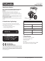
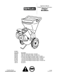
Operator’s Manual
Original Operating Instructions
Chipper/Shredders
Includes:
Model No.
14267
14268
9060300
9060140
9070300
9010400
12547
1692327
1692210
Get parts online at
www.getearthquake.com
Description
212cc Viper Earthquake Chipper / Shredder
212cc Viper Earthquake Chipper / Shredder (CE)
GAS/OIL
8.50 Torque Rated Briggs Earthquake Chipper / Shredder
RATIO
8.25 Torque Rated Briggs Earthquake Chipper / Shredder
(CE)
11.50 Torque Rated Briggs Earthquake Chipper / Shredder
14.50 Torque Rated Briggs Earthquake Chipper / Shredder
14.50 Torque Rated Briggs Earthquake Chipper / Shredder (CE)
Tow Bar Kit
Vacuum Kit
50:1
P/N: 14306
ECN: 9496
REV2: 01/03/13
© 2013 Ardisam, Inc.
All Rights Reserved
Operator’s Manual
Chipper/Shredders
INTRODUCTION
Congratulations on your investment in quality. Thank you for purchasing a Chipper/Shredder from Earthquake™. We have worked to
ensure that your product meets the highest standards for usability and durability. With proper care, your Chipper/Shredder will provide
many years of service.
Please read this entire manual before installation and use. Earthquake reserves the right to change, alter or improve the product
and this document at any time without prior notice.
CONTENTS
Registration.........................................................................................................................................................................................................................................2
Warnings & Safety Precautions.................................................................................................................................................................................................3-8
Assembly........................................................................................................................................................................................................................................9-11
Features & Controls.........................................................................................................................................................................................................................12
Operation & Storage................................................................................................................................................................................................................ 13-14
Recommendations & Maintenance................................................................................................................................................................................... 15-19
Troubleshooting & Repair..................................................................................................................................................................................................... 20-22
Specifications....................................................................................................................................................................................................................................23
Parts & Accessories.........................................................................................................................................................................................................................23
Parts Breakdown....................................................................................................................................................................................................................... 24-30
Certificates of Conformity..................................................................................................................................................................................................... 31-35
Warranty...................................................................................................................................................................................................................................... 36-37
FEDERAL EMISSIONS INFORMATION
Earthquake warrants to the retail purchaser, that this small, off-road engine
was designed, built and equipped to conform at the time of initial sale to all
applicable regulations of the U.S. Environmental Protection Agency (EPA).
Serial
Number
REGISTRATION AND SERVICE
Record the engine model number and serial number in the space provided for easy reference when ordering parts or requesting
technical support. Excluding emissions-related warranty items, the warranty is valid only if the completed registration is received by
Ardisam within 30 days of purchase. (SEE WARRANTY SECTION FOR MORE INFORMATION.) You can register your warranty online
by visiting www.getearthquake.com, or by mailing it to: Ardisam, 1160 Eighth Avenue, Cumberland, WI 54829. If you do not have a
computer, call our customer service department at (800) 345-6007 Mondays through Fridays from 8 a.m. to 5 p.m. CST.
OWNERSHIP RECORDS
Owner’s Name:
Owner’s Address:
City:
Model Number:
Date of Purchase:
Notes:
State/Province:
Serial Number:
Zip Code/Postal Code:
This manual may contain information for several models. Read and keep this manual for future reference. This manual contains
important information on SAFETY, ASSEMBLY, OPERATION, AND MAINTENANCE. The owner must be certain that all the product
information is included with the unit. This information includes the MANUAL, the REPLACEMENT PARTS and the WARRANTIES.
This information must be included to make sure state laws and other laws are followed. This manual should remain with the
engine even if it is resold.
2
Check for parts online at www.getearthquake.com or call 800-345-6007 M-F 8-5
Operator’s Manual
Chipper/Shredders
SAFETY
OWNER’S RESPONSIBILITY
Accurate assembly, and safe and effective use of the chipper/
shredder is the owner’s responsibility.
• Read and follow all safety instructions.
• Carefully follow all assembly instructions.
• Maintain the chipper/shredder according to directions and
schedule included in this Earthquake operator’s manual.
• Ensure that anyone who uses the chipper/shredder is
familiar with all controls and safety precautions.
SPECIAL MESSAGES
Your manual contains special messages to bring attention to
potential safety concerns, machine damage as well as helpful
operating and servicing information. Please read all the information carefully to avoid injury and machine damage.
NOTE: General information is given throughout the manual
that may help the operator in the operation or service of
the machine.
IMPORTANT SAFETY PRECAUTIONS
Please read this section carefully. Operate the chipper/shredder according to the safety instructions and recommendations
outlined here and inserted throughout the text. Anyone who
uses this chipper/shredder must read the instructions and be
familiar with the controls. Learn how to control the chipper/
shredder at all times.
This symbol points out important safety instructions
which if not followed could endanger your personal
safety. Read and follow all instructions in this manual
before attempting to operate this equipment.
• Do not allow children to operate this chipper/shredder. Keep small
children away from the area being tilled. Do not allow adults to
operate the chipper/shredder without proper instruction.
PREPARATION
• Dress appropriately when operating the chipper/shredder.
Always wear sturdy footwear and safety goggles. Never
wear sandals, sneakers or open shoes, and never operate the
chipper/shredder with bare feet. Do not wear loose clothing
that might get caught in moving parts.
• Make sure chipper/shredder is free of debris before starting
the engine.
• Do not allow anyone near the equipment while it is running.
• Do not operate without the debris bag in place because this
unit discharges debris at high speeds.
DANGER
DANGER INDICATES A SERIOUS INJURY OR FATALITY
WILL RESULT IF THE SAFETY INSTRUCTIONS THAT
FOLLOW THIS SIGNAL WORD ARE NOT OBEYED.
WARNING
WARNING INDICATES A SERIOUS INJURY OR FATALITY
COULD RESULT IF THE SAFETY INSTRUCTIONS THAT
FOLLOW THIS SIGNAL WORD ARE NOT OBEYED.
CAUTION
CAUTION INDICATES YOU CAN OR YOUR EQUIPMENT
CAN BE HURT IF THE SAFETY INSTRUCTIONS THAT
FOLLOW THIS SIGNAL WORD ARE NOT OBEYED.
IMPORTANT
IMPORTANT INDICATES HELPFUL INFORMATION FOR
PROPER ASSEMBLY, OPERATION, OR MAINTENANCE
OF YOUR EQUIPMENT.
WARNING
YOU MUST READ, UNDERSTAND AND COMPLY WITH
ALL SAFETY AND OPERATING INSTRUCTIONS IN
THIS MANUAL BEFORE ATTEMPTING TO SETUP AND
OPERATE YOUR ROTOTILLER.
FAILURE TO COMPLY WITH ALL SAFETY AND
OPERATING INSTRUCTIONS CAN RESULT IN LOSS OF
MACHINE CONTROL, SERIOUS PERSONAL INJURY TO
YOU AND/OR BYSTANDERS, AND RISK OF EQUIPMENT
AND PROPERTY DAMAGE. THE TRIANGLE IN THE TEXT
SIGNIFIES IMPORTANT CAUTIONS OR WARNINGS
WHICH MUST BE FOLLOWED.
CALIFORNIA PROPOSITION 65 WARNING
ENGINE EXHAUST FROM THIS PRODUCT CONTAINS
CHEMICALS KNOWN TO THE STATE OF CALIFORNIA
TO CAUSE CANCER, BIRTH DEFECTS, OR OTHER
REPRODUCTIVE HARM.
• Handle fuel with care; it is highly flammable.
a. Use an approved fuel container.
b. Never add fuel to a running engine or hot engine.
c. Fill fuel tank outdoors with extreme care. Never fill fuel tank indoors.
d. Replace gasoline cap securely and clean up spilled fuel before restarting.
• Never attempt to make any adjustments while the engine is
running.
Check for parts online at www.getearthquake.com or call 800-345-6007 M-F 8-5
3
Operator’s Manual
Chipper/Shredders
TRAINING
1. Read the operating and service instructions carefully. Be
thoroughly familiar with the controls and the proper use of
the equipment. Know how to stop the unit and disengage
the control quickly.
2. Keep the area of operation clear of all persons, particularly
small children, and pets.
IMPORTANT
THE RIGHT AND LEFT SIDES OF YOUR CHIPPER/
SHREDDER ARE DETERMINED FROM THE OPERATING
POSITION, STANDING AND FACING THE UNIT.
ENGINE IS SHIPPED FROM FACTORY WITHOUT OIL. YOU
MUST ADD ENGINE OIL BEFORE STARTING ENGINE.
GENERAL OPERATION
1. Read, understand, and follow all instructions in the manual
and on the unit before starting.
2. Do not put hands or feet near rotating parts or under the
machine. Keep clear of the discharge opening at all times.
3. Only allow responsible adults, who are familiar with the
instructions, to operate the unit (local regulations can
restrict operator age).
4. Be sure the area is clear of other people before operating.
Stop the unit if anyone enters the area.
5. Never direct discharge material toward anyone. Avoid
discharging material against a wall or obstruction.
Material may ricochet back toward the operator.
6. Operate the machine only in daylight or good artificial
light.
7. Do not operate the unit while under the influence of
alcohol or drugs.
8. Always wear eye and hearing protection when operating
this unit.
9. Keep in mind the operator is responsible for accidents
occurring to other people or property.
10.It is a violation of California Public Resource Code Section
4442 to use or operate the engine on or near any forestcovered, brush-covered, or grass-covered land unless the
exhaust system is equipped with a spark arrester meeting
any applicable local or state laws. Other states or federal
areas may have similar laws.
11.Always operate the chipper/shredder outdoors, on a firm,
level, earthen or grassy surface where the unit will be
stable and stay in position. Never attempt to operate
the unit on a slope, or on a wet or slippery surface where
you could slip and fall toward the chipper cone or hopper
openings.
12.Never operate the chipper/shredder on asphalt, concrete,
or other hard surfaces as material being ejected out of the
discharge chute could ricochet, causing injury to you or
bystanders.
13.Always obey the size limitations for tree limbs and
branches stated in the Waste Materials Guide portion of
this manual.
14.Never leave the machine running unattended. Always turn
off the engine, wait for the rotor to come to a complete
stop, and disconnect the spark plug before leaving the
area. Always move the unit to a safe storage area when not
in use.
4
DANGER
THE CHIPPER/SHREDDER HAS SPINNING BLADES
THAT CAN AMPUTATE HANDS AND FEET. DO NOT
PLACE HANDS OR FEET IN THE HOPPER OR CHIPPER
CONE, OR DISCHARGE CHUTE.
WARNING
THIS UNIT DISCHARGES DEBRIS AT HIGH SPEEDS.
ALWAYS WEAR PROTECTIVE GOGGLES AND DO NOT
OPERATE WITHOUT THE DEBRIS BAG IN PLACE.
DO NOT ALLOW ANYONE IN THE AREA WHILE THE
UNIT IS RUNNING. IF SOMEONE DOES ENTER THE
AREA, SHUT THE UNIT OFF IMMEDIATELY UNTIL
THEY LEAVE. ORGANIZE THE WORK AREA PRIOR TO
STARTING WORK.
15.Always maintain secure footing and solid balance while
starting or operating the chipper/shredder. Never lean
directly over the machine.
16.Always stand to the side of the chipper cone when feeding
tree limbs and branches into the unit, as tree limbs,
branches, and harder woods may kick back while being
chipped.
17.Always keep hands out of the chipper cone and shredder
hopper when feeding materials. Never wrap fingers tightly
around branches as you are feeding them into the unit,
as a sudden inward surge could pull your hands and arms
into the unit.
18.Never allow material to build up in the discharge area or
shredding chamber, as this may cause new material being
fed into the machine to kickback with sufficient force to
injure you or other bystanders.
19.Never allow material to build up around the engine during
chipper/shredder operation. This could result in a fire, or
overheating of the engine.
20.Never attempt to reposition or move the chipper/shredder
unit while it is running. Doing so could cause the machine
to tip over, and reaching to steady the unit could result in
accidental insertion of your hands into the chipper cone or
shredder hopper areas.
Check for parts online at www.getearthquake.com or call 800-345-6007 M-F 8-5
Operator’s Manual
Chipper/Shredders
21.Never continue to operate the machine if it starts
making unusual noise or vibration. Shut the engine off
immediately, allow the rotor to stop, disconnect the
spark plug wire and secure the wire away from the spark
plug. Inspect the unit for any signs of damage or foreign
material in the chipping or shredding areas. Remove
any solid material that may be preventing the unit from
operating properly.
22.Never attempt to clear clogs from the chipper cone,
shredder hopper or discharge chute while the unit is
running. Always shut the engine off, allow the rotor to
come to a complete stop, and remove the spark plug wire
from the spark plug before removing excess materials.
23.Never attempt to perform any maintenance, repairs,
or attachment of accessories while the unit is running.
Always shut the unit off, allow the rotor to come to a
complete stop, and remove the spark plug wire from the
spark plug before beginning these activities.
24.Always make sure that the shredding chamber, shredder
hopper, and chipper cone are empty before starting the
unit after it has been idle. Attempting to start the unit with
material in these areas could cause the engine starting
cord to stop suddenly, injuring your hand and fingers, or
toppling the unit over. Vibration is generally a warning
sign of trouble.
25.Before cleaning, repairing, or inspecting, shut off the
engine and make certain that all moving parts have come
to a complete stop. Disconnect the spark plug wire and
secure the wire away from the spark plug to prevent
accidental starting.
26. Do not operate the engine in a confined space where
dangerous carbon monoxide fumes can collect.
27.Never operate the machine without proper guards, plates,
or other safety protective devices in place.
28.Use only attachments and accessories approved of by the
manufacturer of the machine.
TRANSPORTING AND STORAGE
1. Always observe safe refueling and fuel handling practices
when refueling the unit after transportation or storage.
2. Never store the unit (with fuel) in an enclosed poorly
ventilated structure. Fuel vapors can travel to an ignition
source (such as a furnace, water heater, etc.) and cause an
explosion. Fuel vapor is also toxic to humans and animals.
3. Always use the hopper handle and built-in wheels to
move the chipper/shredder. Never lift the unit using the
fuel tank for support. If the unit must be lifted , always
use at least two people, and always grip the unit securely
using the front leg and hopper handle.
4. Always follow the engine manual instructions for storage
preparations before storing the unit for both short and
long term periods.
5. Always follow the engine manual instructions for proper
start-up procedures when returning the unit to service.
6. Never store the unit or fuel container inside where there
is an open flame or pilot light, such as in a water heater.
Allow unit to cool before storing.
CHILDREN
Tragic accidents can occur if the operator is not alert to the
presence of children. Children are often attracted to the unit and
the operating activity. Never assume that children will remain
where you last saw them.
1. Keep children out of the work area and under the watchful
care of another responsible adult.
2. Be alert and turn unit off if children enter the area.
3. Never allow children to operate the unit.
EMISSIONS
1. Engine exhaust from this product contains chemicals
known, in certain quantities, to cause cancer, birth defects,
or other reproductive harm.
2. Look for the relevant Emissions Durability Period and Air
Index information on the engine emissions label.
IGNITION SYSTEM
1. This spark ignition system complies with Canadian ICES002.
SERVICE AND MAINTENANCE
Safe Handling of Gasoline
1. Extinguish all cigarettes, cigars, pipes, and other sources of
ignition.
2. Use only approved gasoline containers.
3. Never remove the gas cap or add fuel with the engine
running. Allow the engine to cool before refueling.
4. Never fuel the machine indoors.
5. Never store the machine or fuel container where there is
an open flame, spark, or pilot light such as near a water
heater or other appliance.
6. Never fill containers inside a vehicle or on a truck bed with
a plastic bed liner. Always place containers on the ground
away from your vehicle before filling.
7. Remove gas-powered equipment from the truck or
trailer and refuel it on the ground. If this is not possible,
then refuel such equipment on a trailer with a portable
container, rather than from a gasoline dispenser nozzle.
Check for parts online at www.getearthquake.com or call 800-345-6007 M-F 8-5
5
Operator’s Manual
Chipper/Shredders
Safety Decals
This unit has been designed and manufactured to provide you with the safety and reliability you would expect from an industry
leader in outdoor power equipment manufacturing.
Although reading this manual and the safety instructions it contains will provide you with the necessary basic knowledge to
operate this equipment safely and effectively, we have placed several safety labels on the unit to remind you of this important
information while you are operating your unit.
All DANGER, WARNING, CAUTION and instructional messages on your unit should be carefully read and obeyed. Personal bodily
injury can result when these instructions are not followed. The information is for your safety and it is important! The safety decals
below are on your unit.
If any of these decals are lost or damaged, replace them at once. See your local dealer for replacements.
These labels are easily applied and will act as a constant visual reminder to you, and others who may use the equipment, to follow
the safety instructions necessary for safe, effective operation.
Decal - Operating Instructions,
North American Models
DANGER
WARNING
To avoid serious
personal injury from
rotating cutting
blades, keep hands
out of inlet while
machine is running.
Avoid Serious Injury or Death
• Read and follow the operating instructions.
• Know the location and function of all controls.
• Wear proper safety goggles and hearing
protection.
• Never wear loose clothing.
• Keep hands and clothing clear of material
being pulled into the unit.
• Keep hands and feet away from the discharge
chute area.
NO HANDS BELOW THIS LINE
Decal - Danger,
Rotating Cutting Blades,
North American Models
• Keep safety devices (guards & shields)
in place and working.
• Do not operate when children or others
are present.
• Be sure all moving parts have stopped
before placing hands near the cutting
blades.
• When leaving the machine, shut off the
engine.
1731918
1731919
Decal - Danger,
Rotating Cutting Blades, Warning, Debris,
North American Models
DANGER
DANGER
Amputation Hazard
To avoid serious personal injury from rotating
cutting blades, keep hands out of inlet while
machine is running.
1732039
1731920
Decal - Danger,
Rotating Cutting Blades,
CE Models
Amputation
Hazard
WARNING
Thrown Objects
Hazard
To avoid serious personal injury from
To avoid serious personal injury from
rotating cutting blades, keep hands out discharged debris, never operate
of discharge while machine is running. without the discharge bag installed.
1732181
Amputation Hazard
6
Decal - Operating Instructions, CE
Models
1731921
Decal - Danger,
Thrown Objects, Do Not Operate
Without Collection Bag,
CE Models
Check for parts online at www.getearthquake.com or call 800-345-6007 M-F 8-5
Operator’s Manual
Chipper/Shredders
Safety Icons (European Models)
Warning: Read Operator’s Manual.
Danger: Thrown Objects.
Read and understand the Operator’s
Manual before using this machine.
This machine is capable of throwing
objects and debris. Keep bystanders
away.
Danger: Amputation Hazard.
Danger: Thrown Objects.
To avoid serious personal injury from
rotating cutting blades, keep hands out
of inlet while machine is running.
This machine is capable of throwing
objects and debris. Keep bystanders
and children away when engine is
running.
1731919
1731919
Danger: Wear Appropriate Safety
Equipment.
Danger: Do Not Place Hands in
the Machine.
This machine is capable of throwing
objects and debris. Always wear safety
goggles while operating.
To avoid serious personal injury from
rotating cutting blades, keep hands
out of inlet while machine is running.
Do not place hands in areas where this
symbol is present.
This machine’s operating sound power
level is 109 dB(A) or more. Wear
hearing protection while operating.
1731919
1731919
Warning: Disconnect the Spark Plug
Wire Before Servicing.
Disconnect the spark plug wire, and
secure it away from the spark plug
before servicing the unit.
1731919
1731919
Check for parts online at www.getearthquake.com or call 800-345-6007 M-F 8-5
7
Operator’s Manual
Chipper/Shredders
Identification Numbers
When contacting your authorized dealer for replacement
parts, service, or information you MUST have these
numbers.
Record your model name/number, manufacturer’s
identification numbers, and engine serial numbers in the
space provided for easy access. These numbers can be found
in the locations shown.
NOTE: For location of engine identification numbers, refer to
the engine owner’s manual.
CE Models: Place the extra copy of the identification tag in the
manual.
CE Identification Tag Markings
ID Tag
PRODUCT REFERENCE DATA
Model Description Name/Number
This unit complies with European Harmonized Lawn Mower
Standard EN 836, European Machinery Directive 98/37/EC, and
European EMC Directive 89/336/EC
Unit PART Number
Unit SERIAL Number
* Tested according to EN836:1997/A2:2001
Dealer Name
Date Purchased
** Tested according to 2000/14/EC
ENGINE REFERENCE DATA
ARDISAM, INC.
1160 8th Avenue | Cumberland, WI 54829 | USA
Engine Make
Engine Model
Engine Type/Spec
Engine Code/Serial Number
Serial No.
LBLINFOXXXXXX
CE Specifications
Model: XXXXXXX Year: XXXX
Type: Chipper Shredder Mass: XX kg
Max. Operating Speed: XXXX rpm
LPA (dBA): XXX LWA (dBA): XXX
Model Number: 9060140 / 9010140
Engine Maximum RPMs: 3700
Power Rating: 4 kW
Mass: 52kg
Noise Guaranteed Sound Power (LwA): 109 dB(A)
Intended Use /
Foreseeable Misuse
Noise Sound Pressure Level (LpA): 96 dB(A)
This is a petrol engine-powered chipper/shredder that breaks
up leaves and wooded pieces such as tree branches, brush and
limbs into smaller volume via a high-speed rotor containing
chipping blades and shredding hammers. It shall not be used
for any other purpose.
8
Check for parts online at www.getearthquake.com or call 800-345-6007 M-F 8-5
Operator’s Manual
Chipper/Shredders
Assembly
Install Chipper Cone - All Models
1. Position the chipper cone (A) over the three 5/16-18
threaded studs protruding from the engine plate, and
attach using three 5/16-18 flange nuts (B). SEE FIGURE 1
A
2. Rotate cone and cone base away from engine so cone
does not contact engine.
3. Tighten the flange nuts securely.
Install the Hopper - All Models
1. Attach the hopper to the rotor housing. Make sure
to engage the metal lip of the hopper liner inside the
housing.
2. Secure the hopper to the rotor housing using two 5/16 x
1/2 hex head bolts, two 5/16 flat washers. Do not tighten
hardware at this time. SEE FIGURE 2
3. From the inside of the hopper install one 5/16-18 flange
nut on each 5/16 weld stud. Finger tighten only at this
time.
B
FIGURE 1 - Installing the Chipper Cone
A. Metal Cone Assembly
B. 5/18-18 Flange Nut
4. Check that the hopper is seated correctly and tighten all
hardware.
Install the Handle - All Models
1. Lift the hopper handle up until the outer holes in the
handle align with the holes in the shredder hopper and
secure with 1/4-20 x 3/4 screws, washers, and nuts (A).
Insert the screws from the outside of the shredder hopper.
SEE FIGURE 3
FIGURE 2 - Attaching the Hopper
A
FIGURE 3 - Installing the Hopper Handle
A. 1/4-20 x 3/4 Screw & Nut
Check for parts online at www.getearthquake.com or call 800-345-6007 M-F 8-5
9
Operator’s Manual
Chipper/Shredders
ATTACHING HOPPER EXTENSION TO HOPPER
For European models only (14268, 9060140, and 12547)
Tools Required:
5/32” Hex drive wrench (i.e: allen wrench)
hopper extension
7/16” Wrench for 1/4-20 flange nut
hopper extension
NOTE: Assemble extension before adding fuel or engine oil.
To attach the hopper extension:
1) Before bolting the handle into position, slide one hopperflange
ex- nut
tension half (1709470) over the rim of the hopper. The groove
around the inside bottom of the hopper extension should fitflat washer
bolt the top of the
BALLOON #over thePrim
A R T1/4-20
#around
D Ehopper.
SC R IP TIO N SEE FIGURE 4
1
1960507
the
22)Ensuring
1930642
3
flange nut
CE/QTY.
B O LT 1 / 4 -2 0 X 3 / 4 SB H B LK ZN
hopper and NUT
hopper
extension
1/4-20 HFLTPLK
BLK ZN holes are now
aligned 1along
the top rimE Xof
the hopper, place a 1/4-20 x 3/4
709470
TE N SIO N C H IP P E R H O P P E R C E
bolts (1960507) through each of the four holes in the extension
and hopper. Secure bolts in place with the included 17/64 x 5/8
flat washers (1921319) and 1/4-20 flange nuts (1930642). DO
NOT fully tighten hardware at this point. SEE FIGURE 4
flat washer
16
16
2
1/4-20 bolt
FIGURE 5
3) Bolt handle into position using appropriate hardware. Lay the
unit down, resting the handle on a piece of cardboard to prevent scratching.
4) Follow Step 1 to install the second extension half to the opposite
side of the hopper. Again, the bottom groove of the hopper
extension should fit over the rim at the top of the hopper. Align
the bolt holes between the top of the hopper and bottom of the
hopper extension and insert hardware. SEE FIGURE 5
1/4-20 bolt
5) Place a 1/4-20 x 3/4 bolt (1960507) in each of the three holes
along the two seams of the joined hopper extension halves.
Secure each bolt with a flat washer and flange nut. DO NOT
fully tighten. SEE FIGURE 6
1/4-20 bolt
6) Place bolt through each of the two holes on top of the joined hopper
extension. Secure with flat washer and flange nut. SEE FIGURE 7
7) Once all hardware has been inserted, use 5/32” allen wrench and
7/16” wrench to fully tighten all hardware, including those around
hopper rim and along the hopper extension seams.
1/4-20 bolt
FIGURE 6
1/4-20 bolt
hopper extension
hopper extension
1/4-20 bolt
flange nut
flat washer
1/4-20 bolt
flange nut
flat washer
3
FIGURE 7
3
1/4-20 bolt
1/4-20 bolt
2
FIGURE 4
1/4-20 bolt
10
1
Check for parts online at www.getearthquake.com or call 800-345-6007 M-F 8-5
Operator’s Manual
Chipper/Shredders
Slide bag over discharge chute.
Make sure bag
noose fits over top
of discharge chute
and notch in chute
bottom.
Slide bag over dis-
Lift discharge
charge
chute
andchute.
slide
Make
bag
bag
oversure
chute.
noose
fits
over top
Make
sure
bag
of discharge
noose
fits over chute
and
notch in chute
top
of discharge
chute
and notch
bottom.
in chute bottom.
Pull drawstring tight.
Pull drawstring tight.
FIGURE 8 - Discharge Bag (North American Models)
Install Discharge Bag
This product comes with a discharge bag for collection
of debris as it exits the discharge chute. Install the bag as
shown in FIGURE 8 or 9.
Add Engine Oil
Refer to “Engine Oil Type and Capacity” in the Regular
Maintenance section for oil type and fill procedures.
FIGURE 9 - Discharge Bag (CE Models)
Add Fuel
Refer to “Adding Fuel” in the Operation section for fuel
specifications and filling procedures.
Check for parts online at www.getearthquake.com or call 800-345-6007 M-F 8-5
11
Operator’s Manual
Chipper/Shredders
Features & Controls
Control Functions
The information below briefly describes the function of individual controls. Operating requires the combined use of several controls
applied in specific sequences. To learn what combination and sequence of controls to use for various tasks see the OPERATION
section.
Engine Stop / Throttle Control
The engine stop / throttle control lever controls turn the
engine off and controls the engine speed. Move the throttle
right to increase engine speed and left to decrease engine
speed. Moving the lever all the way to the left stops the
engine. Always operate at FULL throttle (lever fully right).
Recoil Starter
The recoil starter is used to turn the engine over for starting.
Fuel Shut-Off Valve
The fuel shut-off valve is located below the air cleaner
housing. Always close the valve when the unit is not in use.
Fuel Tank
To remove the cap, turn counterclockwise.
Chipper Cone / Shredder Hopper
Chipper Cone: The chipper cone is located on the front of
the unit next to the engine. Insert branches and tree limbs
up to approximately 3” (7.6 cm) in diameter into the chipper
cone. NEVER insert hands past the mouth of the cone.
Shredder Hopper: The shredder hopper is on top of the
unit. Leaves and other light waste can be loaded into the
shredder hopper. NEVER insert hands into the hopper .
Debris Bag: Use the debris bag to collect the material
discharged from the unit. Do not operate the unit without
the debris bag in place.
Choke
Close the choke for cold starting. Open the choke once the
engine starts. A warm engine may not require choking. Move
the lever right to close the choke.
12
Check for parts online at www.getearthquake.com or call 800-345-6007 M-F 8-5
Operator’s Manual
Chipper/Shredders
General Operating Safety
Be sure to read all information in the Safety and Operation
sections before attempting to operate this unit. Become
familiar with all of the controls and how to stop the unit.
Upon start-up and shut-down, you may hear the metalto-metal sound of the triangular hammers and J-hammers
positioning themselves on the rotor. This is normal. If
this sound continues after the machine has reached full
speed, contact your dealer for an inspection of the unit.
Overloading the equipment will shorten its life, and can
cause mechanical failures.
Chipper Operation
The chipper is designed to handle tree limbs and branches
up to approximately 3” (7,6 cm) in diameter. The chipping
knives also permit the processing of course organic matter
like corn stalks. Tree branches must be inserted large-end
first into the chipper cone. Since occasional kick-backs may
occur, always stand off to the side of the unit. Allow the selffeeding action of the unit to draw the sticks in.
Shredder Operation
The shredder is designed to shred light brush, leaves, and
other soft but bulky organic waste. As material is loaded
into the shredder hopper it is pulled into the path of the
triangular and J-hammers by air flow.
Vacuum Attachment (Optional)
In addition to the chipper cone and hopper, loose debris
may be processed by the Vacuum hose adapter kit. Leaves
may be raked directly into the leaf tray where vacuum action
will draw them into the shredder. For hard-to-reach areas,
the nozzle and hose assembly may be used. The strength of
the Vacuum may be changed using the rotating sleeve on
the nozzle. (See Vacuum Kit parts explosion on page 28.)
Operating Location
Select an area with firm, level ground, covered by dirt or
grass. Do not operate on wet or slick surfaces, or near
bystanders. Locate and organize the materials to be
processed so that you don’t have to walk in front of the inlet
or discharge openings, and so you have adequate room to
work safely.
Adding Fuel
To add fuel:
1. Remove the fuel cap (see Figure 1).
2. Fill the tank. Do not overfill. Leave room in the tank for
fuel expansion. Refer to your engine manual for specific
fuel recommendations.
3. Install and hand tighten the fuel cap.
DANGER
THE EXHAUST FROM THIS PRODUCT CONTAINS
CARBON MONOXIDE GAS. CARBON MONOXIDE IS A
COLORLESS, ORDERLESS AND TASTELESS GAS THAT
CAN CAUSE DIZZINESS, NAUSEA, UNCONSCIOUSNESS
OR EVEN BRAIN DAMAGE AND DEATH IF INHALED
FOR PROLONGED PERIODS.
OPERATE THE UNIT OUTDOORS IN A WELL
VENTILATED LOCATION ONLY. KEEP CHILDREN, PETS
AND BYSTANDERS AWAY.
FAILURE TO FOLLOW THESE INSTRUCTIONS MAY
RESULT IN SERIOUS INJURY OR DEATH
WARNING
TO AVOID SERIOUS PERSONAL INJURY FROM
ROTATING CUTTING BLADES, KEEP HANDS OUT OF
INLET WHILE MACHINE IS RUNNING.
WARNING
GASOLINE IS HIGHLY FLAMMABLE AND MUST BE
HANDLED WITH CARE. NEVER FILL THE TANK WHEN
THE ENGINE IS STILL HOT FROM RECENT OPERATION.
DO NOT ALLOW OPEN FLAME, SMOKING OR MATCHES
IN THE AREA. AVOID OVER-FILLING AND WIPE UP ANY
SPILLS.
WARNING
DO NOT USE GASOLINE CONTAINING METHANOL,
GASOHOL CONTAINING MORE THAN 10% ETHANOL,
GASOLINE ADDITIVES OR WHITE GAS BECAUSE
ENGINE/FUEL SYSTEM DAMAGE COULD RESULT.
Starting the Engine
1. Set the throttle to FULL.
2. Close the choke.
NOTE: A warm engine may not require choking.
3. Place one foot on the front support leg to hold the unit
firmly in place.
4. Pull the starting rope out to begin turning the engine over.
Pull slowly at first and increase speed with each successive
pull.
5. After the engine starts, open the choke and move the
engine throttle control to SLOW. Warm up the engine by
running it for at least a minute.
6. Set throttle to FULL and begin chipping/shredding.
Check for parts online at www.getearthquake.com or call 800-345-6007 M-F 8-5
13
Operator’s Manual
Chipper/Shredders
Stopping the Engine
Storage
NOTE: In the event of an emergency the engine can be stopped by
setting the throttle control to STOP.
Before you store your unit for the off-season, read the
Maintenance and Storage instructions in the Safety Rules
section, then perform the following steps:
1. Slide the throttle control fully left to the STOP position.
NOTE: Upon start-up and shut-down, you may hear the metalto-metal sound of the triangular hammers and J-hammers
positioning themselves on the rotor. This is normal.
2. After the engine has stopped moving, remove the spark
plug wire and remove any debris from the unit and
engine.
• Perform engine maintenance and storage measures listed
in the engine owner’s manual. This includes draining the
fuel system, or adding stabilizer to the fuel (do not store a
fueled unit in an enclosed structure - see warning).
Before starting the unit after it has been stored:
• Check all fluid levels. Check all maintenance items.
Processing Materials
• Perform all recommended checks and procedures found
in the engine owner’s manual.
Most materials to be processed can be handled more
efficiently by following these tips.
• Allow the engine to warm up for several minutes before
use.
Chipping Tips:
• Prune branches down close to the main branch to make
feeding them into the chipper cone easier.
• Large, hard, dried tree branches that resist chipping can
be processed by rotating them as you alternately insert
and retract them.
• If the material to be chipped is extremely hard, kicks back
forcefully when being fed into the chipper cone, or cannot
be easily controlled, remove the material immediately and
set it aside.
• If additional force is required to insert materials into the
chipper, the blades probably need to be sharpened.
Consult the Troubleshooting and Repair section of this
manual, or see your authorized dealer.
• Maintain control of the materials you are feeding to
prevent them from whipping around.
• Do not insert short pieces of material into the chipper
cone by hand. Use a larger piece of material to force them
into the chipper cone.
Shredding Tips
• Don’t overload the shredder by dumping large volumes of
material into the hopper opening.
• Alternate loads of wet and dry material to prevent the
discharge from becoming plugged.
• Never use any object to force material into the shredding
chamber. It could get caught in the shredding hammers
and damage the unit.
14
Check for parts online at www.getearthquake.com or call 800-345-6007 M-F 8-5
Operator’s Manual
Chipper/Shredders
Chipping & Shredding Recommendations
Operation
Type of Waste Permitted Size Limitations
Notes
Shredding
Dry or moist organic material
including leaves, plants,
flowers, fruits, or vegetables.
Alternately chip or shred moist green waste
with dry waste to avoid plugging of the
discharge chute.
Branches and twigs up to 1/2”
diameter and 18” long.
Process at a feeding rate that allows the
rotor to keep up and maintain a high rate of
speed.
Chipping
Long, thicker tree limbs or
small bunches of smaller sticks
grouped together for ease of
handling.
Tree limbs and branches,
or bundles of small sticks
grouped for easier handling.
Maximum diameter of
approximately 3” (7,6 cm).
Bulky tree limbs should be pruned close to
the main stem. Always use a shorter piece
of wood to push end pieces into the chipper
cone. Never place hands in the chipper
cone.
Never chip very hard or dry materials such as
kiln dried dimensional lumber (2x4’s etc.) or
other building materials.
Never use the chipper to process pressuretreated wood products.
Vacuum
Attachment
Light, loose, dry waste such
as leaves, grass clippings, or
sawdust.
Small materials that will not
obstruct the vacuum hose.
Check for parts online at www.getearthquake.com or call 800-345-6007 M-F 8-5
The vacuum is engineered for small, loose
waste and for cleaning around decorative
landscaping and flower beds. Twigs, wet
leaves, and other bulky materials will clog
the hose or obstruct the shredding chamber.
15
Operator’s Manual
Chipper/Shredders
Maintenance
Schedule & Procedures
The following schedule should be followed for normal care of your unit.
SAFETY ITEMS
Before Every 5 Every 25 Every 100 Every
Each
Hours Hours
Hours
250
Use
Hours
Check for loose hardware
Spring &
Fall
X
X
Check all safety labels
X
Inspect cone, hopper, and guards.
X
CHIPPER MAINTENANCE ITEMS
Clean debris from engine and chipper. **
Before Every 5 Every 25 Every 100 Every
Each
Hours Hours
Hours
250
Use
Hours
X
X
Inspect/Rotate Shredding Hammers
X
Inspect/Rotate Chipping Knives
ENGINE MAINTENANCE ITEMS
Check Engine Oil Level *
Spring &
Fall
X
Before Every 8 Every 25 Every 50 Every
Each
Hours Hours
Hours
100
Use
Hours
X
Spring &
Fall
X
Change Engine Oil * **
X
Check / Change Engine Air Filter * **
X
Replace Spark Plug *
X
* Refer to engine owner’s manual. Change original engine oil after initial break-in period of 5-8 hours.
** More often in hot (over 85° F: 30° C) weather or dusty operating conditions.
Check for Loose Hardware
Inspect Cone, Hopper, & Guards
Service Interval: Every 5 hours; every spring and fall.
Service Interval: Every spring and fall.
Inspect the unit, checking for loose hardware or components.
Pay special attention to the hardware attaching the chipper
cone, hopper, axle, and front leg.
Check that the chipper cone, shredder hopper, and discharge
guards are in place, undamaged, and secure. Replace any
damaged or missing parts.
Check Safety Labels
Service Interval: Every spring and fall.
Check that the safety labels are in place and undamaged.
Sample illustrations and part numbers of the decals can be
found on page 6. Replace any damaged or missing decals.
16
Check for parts online at www.getearthquake.com or call 800-345-6007 M-F 8-5
Operator’s Manual
Chipper/Shredders
A
fins
B
FIGURE 10 - Clean Debris from Engine Cooling Fins
Clean Debris from Engine & Chipper
Service Interval: Before each use and every 100 hours.
The engine requires air flow to cool itself and for
combustion. Before each use, clean any debris from the
unit especially from around the air shroud intake, air filter,
and muffler. Every 100 hours, remove the engine air shroud
and clean out any debris from the engine cooling fins (SEE
FIGURE 10). We recommend having this service performed
by an authorized dealer.
FIGURE 11
A. J-Hammer Wear Area
B. Access Panel
A
Inspect / Rotate Shredding Hammers
Service Interval: Every 25 Hours, or As Necessary
The shredding hammers of this unit can be rotated to
provide a new cutting surface as required. The triangular
hammers can be rotated twice, then flipped over for a total
of 6 sharp cutting surfaces. The J-hammers can be flipped
over once. To inspect the shredding hammers:
FIGURE 12
A. Triangular Hammer Wear Area
1. Disconnect the spark plug wire and secure it away from
the spark plug.
2. Remove the small circular access panel (B) from the back
of the shredder housing. SEE FIGURE 11
3. Inspect the cutting edges of the triangular hammers (A)
and J-hammers (A). SEE FIGURES 11 AND 12
To rotate or replace the shredding hammers, see the
Troubleshooting and Repair section.
WARNING
AMPUTATION HAZARD. TO AVOID SERIOUS INJURY
FROM ACCIDENTAL STARTING, ALWAYS DISCONNECT
THE SPARK PLUG WIRE AND SECURE IT AWAY FROM
THE SPARK PLUG WHEN SERVICING THE UNIT.
WARNING
TO AVOID SERIOUS INJURY FROM ACCIDENTAL
STARTING, ALWAYS DISCONNECT THE SPARK PLUG
WIRE AND SECURE IT AWAY FROM THE SPARK PLUG
WHEN SERVICING THE UNIT.
Check for parts online at www.getearthquake.com or call 800-345-6007 M-F 8-5
17
Operator’s Manual
Chipper/Shredders
Inspect Chipping Knives
Service Interval: Every 25 Hours, or As Necessary
The chipping knives of this unit can be rotated or sharpened
to provide a new cutting surface as required. When
inspecting the knives be careful to avoid touching the
sharpened edges. To inspect the chipping knives:
1. Disconnect the spark plug wire and secure it away from
the spark plug.
2. Remove the nuts securing the chipper cone to the front
of the chipper. Remove the chipper cone (A) to access the
knives. SEE FIGURE 13
3. Using the recoil starter, slowly pull the starter rope to
rotate the rotor into position so the blades can be seen.
To sharpen or replace the chipper knives, see the
Troubleshooting and Repair section.
Check / Change Engine Air Cleaner
A
FIGURE 13 - Inspect Chipper Knives
A. Chipper Cone
Service Interval: Every 25 Hours
The engine air cleaner assembly should be opened, inspected,
and the filter element replaced every 25 hours, or as required if
debris has built up in the assembly.
B
C
D
E
To replace the air filter and pre-cleaner assembly:
1. Loosen the screw (A) and remove the filter cover (B). SEE FIGURE 14
2. Inspect the pre-cleaner (C) and air filter element (D). If
either are soiled, then replace.
3. Insert the new pre-cleaner (C) and air filter element (D)
inside the filter cover (B). Make sure the arrows on the
filter element are pointed up, and the lip of the precleaner covers the bottom filter pleats.
4. Insert the cover tabs (F) into the filter base slots.
5. Tilt the cover up into place and tighten the screw (A).
Replace Spark Plug
Please contact your authorized dealer to perform this service.
18
A
F
FIGURE 14 - Change Air Filter.
NOTE: This illustration is for general reference only. Some
engine models may appear different. Refer to the engine
manual for more detailed instruction.
A.Screw
B. Filter Cover
C. Pre-Cleaner (Not included in some engine models)
D. Air Filter Element
E. Air Filter Base
F. Slots and Tabs
Check for parts online at www.getearthquake.com or call 800-345-6007 M-F 8-5
Operator’s Manual
Chipper/Shredders
Engine Oil Type & Capacity
Select a quality engine oil using the chart in Figure 15. 8.5
torque rated models require 5/8 quart (0.6L) of oil.
Use oil classified API Service Class SF,
SG, SH, SJ or better with SAE Viscosity:
30 Conventional**
Check Engine Oil Level
Service Interval: Before Each Use
Check the engine oil level at the oil fill and level check plug
(A). SEE FIGURE 16
5W-30
10W-30
Conventional*
1. Stop the engine and wait for all moving parts to stop.
2. Remove the oil fill and level check plug (A) by twisting
it counter-clockwise. The oil should be filled up to the
mouth of the filler opening as shown in the FIGURE 16
inset.
Change Engine Oil
Service Interval: Every 50 Hours
1. Stop the engine and wait for all moving parts to stop.
Allow the unit to cool before changing the oil.
2. Remove the oil fill and level check plug (A) by twisting it
counter-clockwise. SEE FIGURE 16
3. Place an oil drain pan below the engine and remove the
oil drain plug (B). Allow the oil to drain completely. SEE FIGURE 16
5W-30, 10W-30 Synthetic
°F
-20
0
20 32 40
60
80
100
16
27
38
0 4
*CAUTION: Air cooled engines run hotter than automotive engines.
The use of non-synthetic multi-viscosity oils (5W-30, 10W-30, etc.)
in temperatures above 40º F (4ºC) will result in higher than normal
oil consumption. When using a multi-viscosity oil, check oil level
more frequently.
°C
-30
-18
-7
**CAUTION: SAE 30 oil, if used below 40º F (4ºC), will result in hard
starting and possible engine bore damage due to inadequate
lubrication.
FIGURE 15 - Oil Recommendations
4. Reinstall the oil drain plug (B). Tighten the plug to 125
inch pounds (14 Nm)
A
5. Add oil to the oil fill hole (A) until the oil level is even
with the bottom edge of the oil fill hole. SEE FIGURE 16
B
FIGURE 16 - Oil Fill and Oil Drain
A. Oil Fill & Level Check Plug
B. Oil Drain Plug
Check for parts online at www.getearthquake.com or call 800-345-6007 M-F 8-5
19
Operator’s Manual
Chipper/Shredders
Troubleshooting Chart
While normal care and regular maintenance will extend
the life of your equipment, prolonged or constant use may
eventually require that service be performed to allow it to
continue operating properly.
The troubleshooting guide below lists the most common
problems, their causes, and remedies.
See the information on the following pages for instructions on
how to perform most of these minor adjustments and service
repairs yourself. If you prefer, all of these procedures can be
performed for you by your local authorized dealer.
PROBLEM
WARNING
TO AVOID SERIOUS INJURY, PERFORM MAINTENANCE
ON THE UNIT ONLY WHEN THE ENGINE IS STOPPED.
ALWAYS DISCONNECT THE SPARK PLUG WIRE AND
FASTEN IT AWAY FROM THE PLUG BEFORE BEGINNING
THE MAINTENANCE, TO PREVENT ACCIDENTAL
STARTING OF THE ENGINE.
CAUSE
Engine will not start.
1.
2.
3.
4.
5.
6.
7.
Out of fuel.
Spark plug wire disconnected.
Engine controls not set correctly.
Spark plug fouled.
No compression. Recoil starter pulls with no resistance.
No spark. Ignition problem.
Old or stale fuel.
REMEDY
Add fuel.
Reconnect spark plug wire.
Refer to Starting in the Operation section.
Remove the spark plug, clean or replace.
See your authorized dealer.
See your authorized dealer.
See your authorized dealer.
Engine exhaust is black.
1. Dirty air filter. 2. Choke closed.
Replace air filter. See engine manual.
Open choke.
Engine runs but no material is discharged. 1. Discharge chute clogged. 2. Engine not running at full speed.
Clean out debris. Set throttle control to FAST.
Excessive branch vibration when
1. Chipper knives dull.
chipping materials.
2. Tree limbs are extremely hard or dried out.
Sharpen or replace chipper knives.
Material is not suitable for chipping.
Unusual noise or vibration when.
1. Rotor overloaded with material.
processing material.
2. Hammers are broken, bent, or loose.
3. Hammers frozen in place.
Allow unit to clear itself before adding more material to the hopper.
Check assembly. Tighten or replace as
required.
Check for obstructions and debris. Repair as necessary.
Vacuum not working.
Install lid.
Allow material to dry.
Attach hose per instructions (see hose kit).
Clear blockage or replace.
Set throttle control to FAST.
20
1.
2.
3.
4.
5.
Hopper lid not in place. Material too wet.
Hose not attached properly.
Hose obstructed or damaged.
Engine not running at full RPM.
Check for parts online at www.getearthquake.com or call 800-345-6007 M-F 8-5
Operator’s Manual
Chipper/Shredders
FIGURE 18 - Removing the Rotor Housing
FIGURE 17 - Removing the Shredder Hopper
E
F
Repair
G
Shredding Hammer Rotation and Replacement
The cutting edges of the shredding hammers may eventually
wear out requiring rotation of the hammer or replacement if
all cutting edges have been dulled.
Triangular hammers can be rotated twice after the first edge
dulls, then flipped over once and rotated again for a total of 6
edges. J-hammers can be flipped over once for a total of two
cutting edges.
To rotate the shredding hammers:
1. Turn the engine off and wait for all moving parts to stop.
2. Disconnect the spark plug wire and secure it away from
the spark plug.
D
C
3. Detach the shredder hopper from the rotor housing. SEE FIGURE 17
B
4. Remove the rotor cover by removing the hardware that
secures it to the main housing. SEE FIGURE 18
5. Note the assembly sequence of the hardware used to
secure the hammers. Using a 5/16” allen wrench remove
the socket head cap screw (A) and related hardware. SEE FIGURE 19
D
C
6. Inspect the hammers (G, H), spacer tubes (D, E), and
hardware. If the spacer tube (D, E) shows signs of wear,
replace it. Inspect and flip, or replace the hammers (G, H).
7. Reassemble the hammers, spacers, washers, and cap
screws. Torque the socket head cap screws (A) to 30-35
ft. lbs. (41-47 N.m.)Refer to Figure 14 for assembly. The
J-hammer (G) on the opposite side of the rotor faces
outward for balanced rotation.
8. Repeat for all the hammers.
A
B
F
A
H
E
FIGURE 19 - Rotor Housing
A.
B.
C.
D.
Socket Hd. Cap Screw
Lock Washer, 3/8
Washer, 7/8
Spacer, Long
Check for parts online at www.getearthquake.com or call 800-345-6007 M-F 8-5
E.
F.
G.
H.
Spacer, Short
Washer, 3/8 (9070300, 9010400, 9010140 only)
J-Hammer
Triangular Hammer
21
Operator’s Manual
Chipper/Shredders
Chipping Knives Sharpening and Replacement
The chipping knives should be sharpened or replaced when
tree limbs require extra force to feed into the chipper cone.
The chipping knives may be sharpened at a 30 degree angle
until the distance between the edge of the blade bevel and
the mounting hole is less than 1/16” (1.6mm). SEE FIGURE 22
WARNING
AMPUTATION HAZARD. TO AVOID SERIOUS INJURY
FROM ACCIDENTAL STARTING, ALWAYS DISCONNECT
THE SPARK PLUG WIRE AND SECURE IT AWAY FROM
THE PLUG WHEN SERVICING THE UNIT.
To inspect, sharpen, or replace the chipping knives:
1. Turn the engine off and wait for all moving parts to stop.
2. Disconnect the spark plug wire and secure it away from
the spark plug.
3. Detach the shredder hopper from the rotor housing. SEE FIGURE 17 (previous page)
WARNING
CUTTING HAZARD. TO AVOID SERIOUS INJURY, AVOID
CONTACTING THE SHARP CUTTING EDGES OF THE
CHIPPING KNIVES.
4. Remove the rotor housing by removing the hardware that
secures it to the main housing. SEE FIGURE 18
5. Remove the chipper cone base. Rotate the rotor such that
one of the chipper knives is visible through the cone hole.
SEE FIGURE 20
6. Using a 1/4” hex wrench, reach into the main housing
and remove the two socket head cap screws and the
chipper knife (SEE FIGURE 21). Make sure to hold onto
the chipper knife through the cone hole, be aware of the
sharp cutting edge. SEE FIGURE 20
7. Inspect, rotate, sharpen, or replace the chipper knife. SEE FIGURE 22
8. Reinstall the chipper knife and tighten the socket head
cap screws to 18-20 ft-lb (24-27 N.m.). We recommend the
use of high strength threadlocker on screws.
9. Rotate the rotor 180 degrees and repeat with the other
chipper knife. Reinstall the rotor cover and shredder
hopper when completed.
cone
hole
chipper
cone base
chipper
knife
socket head
cap screw
FIGURE 21 - Removing the Chipper Knives
Top View
Side View
1/16”
Min
30°
FIGURE 22 - Chipper Knife Minimum Cutting Edge
chipper
knife
FIGURE 20 - Removing the Chipper Cone
22
Check for parts online at www.getearthquake.com or call 800-345-6007 M-F 8-5
Operator’s Manual
Chipper/Shredders
Specifications
NOTE: Specifications are correct at time of printing and are subject to
change without notice.
* Actual sustained equipment horsepower will likely be lower due to
operating limitations and environmental factors.
CHASSIS:
All Models
Chipping CapacityApproximately 3” (7.6 cm)
Shredding Capacity 1/2” x 18” Long
Chipping Knives2
Shredding Hammers 2 J-hammers,
2 triangular hammers
Serial
Number
Waste Reduction Ratio Approximately 20:1
Weight Model 14267 212cc 110 lbs.
Model 14268 212cc 118 lbs.
Model 9060300 8.50 Torque Rating 107 lbs.
Model 9060140 8.25 Torque Rating 115 lbs.
Model 9070300 11.50 Torque Rating 120 lbs.
Model 12547 14.50 Torque Rating 129 lbs.
Model 9010140 14.50 Torque Rating 137 lbs.
Parts & Accessories
Replacement Parts
Replacement parts are available from your authorized dealer.
Always use genuine Earthquake Service Parts.
Optional Accessories
Vacuum Kit Model No. 1692327
Tow Bar Kit Model No. 1692210
Check for parts online at www.getearthquake.com or call 800-345-6007 M-F 8-5
23
Operator’s Manual
Chipper/Shredders
HOPPER & ENGINE GROUP PARTS EXPLOSION
27
23
2
11
3
22A
5
6
1
10
7
4
7
25
4
12
14
22
18
21
24
26
19
8
13
17
28
29
30
20
31
8
8
16
15
32
Optional CE metal cone assembly
P/N 3550842
9
33
24
Check for parts online at www.getearthquake.com or call 800-345-6007 M-F 8-5
Operator’s Manual
Chipper/Shredders
HOPPER & ENGINE GROUP PARTS LIST
KEY #
PART #
DESCRIPTION
QTY.
KEY #
PART #
DESCRIPTION
QTY.
23
-
ENGINE, 14.50 TORQUE RATED
BRIGGS INTEK (9010400)
1
-
ENGINE, 212CC VIPER (14267 &
14268)
1
1
1960507 BOLT, SOCKET BUTTON HD, 1/4-20
X 3/4
10
2
1098100 RETAINER, HOPPER GUARD
1
3
1095100 GUARD, HOPPER
1
4
1930642 NUT, FLANGE, 2-WAY LOCK, 1/4-20
14
5
1709603 SUPPORT, HOPPER GUARD
1
6
3621100 HANDLE
1
7
1919326 WASHER, PLAIN,
17/64 X 5/8 X 3/64
8
8
1931277 NUT, WHIZ, 5/18-18
18
9
3550841 CHIPPER CONE ASSEMBLY, METAL
(OPTIONAL)
1
10
1709469 HOPPER, RED
1
29
3550813 PANEL, CONE TOP FLANGE
1
11
2005612 SAFETY GOGGLES
1
30
3550840 COVER, CONE FLAP
1
31
3550815 WELDMENT, CONE
1
12
1926106 CAP SCREW, HEX,
5/16-18 X 3-1/4 GR5
1
13
3685100 DEFLECTOR
1
14
1709556 DEFLECTOR, FIXED
(EUROPEAN MODELS)
1
15
1960519 NUT, PUSH, 1/2
2
16
1714252 WHEEL & TIRE ASSEMBLY,
11 X 1.75
2
24
1709403 COLLECTION BAG, 24" X 36"
1
25
1713203 PLATE, ENGINE KICKSTAND
1
26
1921515 CAP SCREW, HEX HD,
5/16-24 X 3/4
4
27
1960506 BOLT, SOCKET BUTTON HD, 1/4-20
X 7/8
4
METAL CONE ASSEMBLY PARTS
28
32
33
8930B BOLT, 1/4X3/4 HH GR5 BLK ZN
48752B NUT, FLANGED, TOP LOCK 1/4-20
3550814 PANEL CONE TOP EURO
EUROPEAN MODELS ONLY
4
4
1
ADDITIONAL PARTS (NOT SHOWN)
-
1709480 BASE PLATE, ENGINE
1
-
1713200 SPACER, BRIGGS ENGINE
1
-
1713201 PLATE, KICKSTAND, BRIGGS ENGINE
1
1713203 PLATE, KICKSTAND, BRIGGS ENGINE,
14.50 TORQUE RATED
1
-
1732039 DECAL, DANGER (U.S. VERSION)
CONE
1
17
1924361 WASHER, PLAIN,
17/32 X 1-1/4 X 5/64
2
18
1928635 SCREW, TAPTITE,
3/8-16 X 1-1/4
4
19
1713099 KICKSTAND ROD
1
20
1925205 CAP SCREW, HEX,
5/16-18 X 5/8
1
-
1
21
1917356 LOCK WASHER, 5/16
10
1731920 DECAL, DANGER (CE EUROPEAN
VERSION) CONE
22
1713281 ENGINE PLATE ASSEMBLY (ROTOR
HOUSING)
1
-
1732181 DECAL, DANGER (U.S. VERSION)
1
-
1731921 DECAL, DANGER (CE EUROPEAN)
1
22A
23
4321 ADAPTER PLATE (9050300 & 9050140
ONLY)
1
-
ENGINE, 8.25 TORQUE RATED BRIGGS
CE (9060140)
1
-
ENGINE, 8.50 TORQUE RATED BRIGGS
INTEK HORZ SHAFT (9060300)
1
-
ENGINE, 11.50 TORQUE RATED
BRIGGS (9070300)
1
-
ENGINE, 14.50 TORQUE RATED
BRIGGS CE (12547)
1
-
LBL200201 DECAL, EARTHQUAKE DASH
Check for parts online at www.getearthquake.com or call 800-345-6007 M-F 8-5
1
25
Operator’s Manual
Chipper/Shredders
HOUSING & ROTOR GROUP EXPLOSION
1
10
5
6
4
7
9
8
28
11
13
29
17
14
16
30
10
12
2
2
18
2
15
12
12
3
19
26
20
19
21
31
23
31
22
27
19
25
22
27
19
24
23
25
The J-Hammer (not shown) on the opposite side of the rotor faces outward
for balanced rotation. There is also a second Chipper Knife and Tri-Hammer
(not shown) opposite the ones in the explosion above.
26
Check for parts online at www.getearthquake.com or call 800-345-6007 M-F 8-5
Operator’s Manual
Chipper/Shredders
HOUSING & ROTOR GROUP PARTS LIST
KEY #
PART #
DESCRIPTION
QTY.
KEY #
PART #
DESCRIPTION
QTY.
21
1916950 NUT, HEX 3/8-16
2
1
3525100 LINER, HOPPER
1
2
1917356 LOCK WASHER, SPLIT 5/16
10
22
1709614 SPACER, TUBE
4
3
6518100 CAP SCREW, SOCKET HD 3/8-16 X 5/8
2
23*
4
4
1930642 NUT, 2-WAY LOCK 1/4-20
2
1709616 SPACER, 3/4" O.D. X 3/4" LONG
(9070300, 9010400, 9010140)
5
1919326 WASHER, FLAT 1/4
2
4
6
1960507 BOLT, SOCKET BUTTON HD,
1/4-20 X 3/4
2
1713207 SPACER, 1" O.D. X 33/64" LONG
(9060300, 9060140, 14267, 14268)
24
3307612 HAMMER, TRIANGULAR
2
7
1731918 DECAL, CAUTION (U.S VERSION)
1
25
1960508 CAP SCREW, HEX SOCKET HD W/PATCH
3/8-16 X 2 GR8
4
26
3307100 J HAMMER
2
27
1924940 WASHER, FLAT 7/8" O.D.
4
28
3521100 HOUSING, ROTOR
1
29
3501100 HOUSING, FAN
1
30
3505100 AXLE ASSEMBLY
1
31
1731919 DECAL, CAUTION (CE, EUROPEAN)
8
6005100 CAP SCREW, SOCKET HD 5/16-28 X 1/2
2
9
1919438 NUT, NYLOCK 5/16-18
2
10
1931277 NUT, HEX FLANGE 5/16-18
7
11
3520100 COVER, ROTOR HOUSING
1
12
1920787 CAP SCREW, HEX HD 5/16-18 X 1/2
8
13
3315612 CHIPPER KNIFE
2
14
15*
905100 KEY 1/4 SQ. X 1-7/8
1
3299100 SPACER, ROTOR, .822" LONG (9060300,
9060140, 14267, 14268)
1
1713206 SPACER, ROTOR, .72" LONG (9070300,
9010400, 9010140)
1
16
1924874 WASHER, FLAT 5/16
2
17
1660071 ROTOR HAMMERS & KNIVES ASMY
5/14 CS (9060300, 9060140, 14267,
14268)
1
1660092 ROTOR HAMMERS & KNIVES ASMY
8/14 CS (9070300, 9010400, 9010140)
1
18
6005612 CAP SCREW, SOCKET HD 5/16-24 X 5/8
4
19
1916965 LOCK WASHER, SPLIT 3/8
7
20
6516100 CAP SCREW, SOCKET HD 3/8-24 X 2
1
1676435 WASHER, PLAIN 1/2 X 1-1/4 X 3/16
4
-
1921333 BOLT, HEX HD CAP SCREW, 5/16-18 X
1 GR5
1
-
1714177 ROTOR ASSEMBLY
1
-
1685698 ROTOR KIT (INCLUDES KEY #'S:
2, 17, 22, 23, 26, 29)
1
-
1660071 ROTOR HAMMERS & KNIVES ASSEMBLY (14267, 14268, 9060300, 9060140
MODELS)
1
-
1660092 ROTOR HAMMERS & KNIVES ASSEMBLY
(9070300, 9010400, 9010140 MODELS)
1
* Measure length to determine which spacer to use.
Check for parts online at www.getearthquake.com or call 800-345-6007 M-F 8-5
27
Operator’s Manual
Chipper/Shredders
12727 VACUUM KIT (OPTIONAL ACCESSORY)
14
13
1
3
12
15
11
2
7
4
5
10
9
9
6
KEY #
PART # DESCRIPTION
QTY.
1
1021100 ADAPTER
1
2
1023100 COUPLER
1
3
1025100 PLUG, CAP
1
4
1035100 HOSE, 4" DIA. X 10' LONG
1
5
1027100 LEAF TRAY
1
6
1030100 NOZZLE
1
7
1024100 RING, NOTCHED, 5" DIA. X 3" LONG
1
8
1960294 NUT, HEX FLANGE, 1/4-20
1
9
1921319 WASHER, 1/4
2
10
6041612 BOLT, PHILLIPS TRUSS HD, 1/4-20 X 1-1/2
1
11
1026100 HANDLE
1
12
1028100 GRIP, HANDLE
1
13
5001612 DECAL, DANGER
1
14
12664 HOPPER LID, BLACK
1
15
1919326 WASHER, FLAT, 5/16
3
1732039 DECAL, DANGER
1
-
28
8
Check for parts online at www.getearthquake.com or call 800-345-6007 M-F 8-5
Operator’s Manual
Chipper/Shredders
1692327 TOW BAR KIT (OPTIONAL ACCESSORY)
3
9
6
8
4
5
2
7
5
5
1
KEY #
PART # DESCRIPTION
QTY.
1
1713352 BENT ARM ASSEMBLY
1
2
1713414 ROD ASSEMBLY
1
3
1713357 ROD HOLDER ASSEMBLY
1
4
1710726 PIN, CLEVIS, 5/16 X 1-1/2
4
5
1918196 PIN, QUICK, 3/32 X 1-7/8
5
6
1925205 BOLT, HEX HD CAP SCREW, 5/16-18 X 5/8 GR5
1
7
1423B BOLT, HEX HD CAP SCREW, 5/16-18 X 2 GR5
1
8
1919438 NUT, HEX LOCK, 5/16-18
1
9
118053 PIN, ROUND HD, 3/8 X 2
1
Check for parts online at www.getearthquake.com or call 800-345-6007 M-F 8-5
29
Operator’s Manual
Chipper/Shredders
HOPPER EXTENSION PARTS EXPLOSION, PARTS LIST AND FULL ASSEMBLY
(CE EUROPEAN MODELS ONLY)
KEY #
30
PART NO.
DESCRIPTION
QTY.
1
1960507
BOLT 1/4-20 X 3/4 SBH BLK ZN
16
2
1930642
NUT 1/4-20 HFLTPLK BLK ZN
16
3
179470
EXTENSION CHIPPER HOPPER CE
2
4
1921319
WASHER, PLAIN 17/64 X 5/8 X 3/64 (NOT SHOWN)
16
Check for parts online at www.getearthquake.com or call 800-345-6007 M-F 8-5
Operator’s Manual
Chipper/Shredders
Check for parts online at www.getearthquake.com or call 800-345-6007 M-F 8-5
31
Operator’s Manual
Chipper/Shredders
32
Check for parts online at www.getearthquake.com or call 800-345-6007 M-F 8-5
Operator’s Manual
Chipper/Shredders
Check for parts online at www.getearthquake.com or call 800-345-6007 M-F 8-5
33
Operator’s Manual
Chipper/Shredders
34
Check for parts online at www.getearthquake.com or call 800-345-6007 M-F 8-5
Operator’s Manual
Chipper/Shredders
Check for parts online at www.getearthquake.com or call 800-345-6007 M-F 8-5
35
Operator’s Manual
Chipper/Shredders
CHIPPER/SHREDDERS
Warranty Terms and Conditions
PRODUCT WARRANTY: 1-YEAR LIMITED WARRANTY
Ardisam, Inc., a manufacturing company, warrants this EARTHQUAKE™ CHIPPER/SHREDDER to be free from
defects in the material or workmanship for a period of one year from the date of purchase. During the one-year
warranty of this product, Ardisam will furnish, at their discretion, parts and labor to correct any defect caused by
faulty material or workmanship. Any unit used in a commercial application is covered for a period of 90 days after
purchase. This warranty applies to the original owner with a proof of purchase and is not transferable. For the
warranty to be valid, the product must be registered online, or the warranty card must be filled out and received
by Ardisam, Inc., within 30 days of purchase.
14267 AND 14268 ENGINE WARRANTY: 2-YEAR LIMITED EMISSIONS CONTROL WARRANTY
(SEE EXPLANATION OF EMISSIONS CONTROL WARRANTY PROVISIONS FOR DETAILS)
Ardisam, Inc., a manufacturing company warrants its Viper® Engines under a two-year limited emissions control
warranty to be free from defects in materials and workmanship for the service life of the product not to exceed
twenty-four consecutive months from the date of purchase for consumer applications.
*These warranties apply only to products which have not been subjected to negligent use, misuse, alteration, accident, unauthorized parts, failure to use proper fuel and oil, or if repairs have been performed at non-authorized
service centers. These warranties supersede all other warranties either expressed or implied and all other obligations
or liabilities on our part. Ardisam, does not assume, and does not authorize any other person to assume for us, any
liability in connection with the sale of our products. To be at “No Charge,” warranty work must be sent directly
to Ardisam, Inc. or one of our authorized service centers and performed by them. To obtain warranty service
and/or replacement instructions, contact our customer service department. If you choose to ship your product
to Ardisam for warranty repair, you must first have prior approval from Ardisam by calling our customer service
department for a return material authorization number (RMA#). Under these circumstances, all items must be
shipped prepaid. Ardisam will at no charge, repair or replace, at their discretion, any defective part which falls under
the conditions stated above. Ardisam retains the right to change models, specifications and price without notice.
Earthquake™, Division of Ardisam, Inc.
1160 Eighth Avenue; P.O. Box 666
Cumberland, Wisconsin 54829
800-345-6007 · Fax (715) 822-4180
E-mail: [email protected]
36
Check for parts online at www.getearthquake.com or call 800-345-6007 M-F 8-5
Operator’s Manual
Chipper/Shredders
EXPLANATION OF EMISSIONS CONTROL
WARRANTY PROVISIONS
The United States Environmental Protection Agency, the California Air
Resources Board and Ardisam, Inc., are pleased to explain the emission
control system warranty on your small off-road engine/equipment. In the
United States and California, new small off-road engine/equipment must
be designed, built and equipped to meet the State’s stringent anti smog
standards. Ardisam must warrant the emission control system on your
small off-road engine/equipment for the periods of time listed below provided there has been no abuse, neglect or improper maintenance of your
small off-road engine/equipment.
b) Replacement of parts and other services and adjustments necessary for
required maintenance at or after the first scheduled replacement point;
Viper Engines are designed, built and equipped to meet all EPA and
CARB requirements. It warrants that it is free from defects in material
and workmanship that could cause failure to the warranted part; and
that it is identical in all material respects to the engine described in the
manufacturer's application for certification. When a warrantable condition
exists, Ardisam will repair your engine at no cost to you, including parts and
labor. The engine emissions label will indicate certification information. If
the purchaser is in need of a warrantable repair and is not within 100 miles
distance from an Viper authorized repair center, Ardisam will pay for shipping
costs to and from an authorized Viper repair center.
These items will be covered for a period of two years from the date of the
original purchase. Ardisam warrants that: the components are designed,
built and equipped so as to conform with all applicable regulations adopted
by the EPA; that they are free from defects in material and workmanship
that could cause failure to the engine or other; and that the components
used are identical in all material respects to the engine described in the
manufacturer's application for certification. The warranty period begins
on the date the engine is originally purchased.
Listed below are the parts covered by the emissions control systems
warranty. Some parts listed below may require scheduled maintenance
and are warranted up to the first scheduled replacement point for that
part. Coverage under this warranty includes only the parts listed below (the
emission and evaporation control systems) if so equipped:
The owner is responsible for the proper use and maintenance of the engine.
Viper recommends that all receipts and records covering the performance
of regular maintenance be retained in case questions arise. If the engine
is resold during the warranty period, the maintenance records should be
transferred to each subsequent owner. Ardisam reserves the right to deny
warranty coverage if the engine has not been properly maintained; however,
Ardisam may not deny warranty repairs solely because of the lack of repair
maintenance or failure to keep maintenance records.
•
Air Filter Assembly (only to the first scheduled replacement point)
•
Fuel Filter (only to the first scheduled replacement point)
•
Carburetor
•
Fuel Lines, Fuel Line Fittings and Clamps
•
Fuel Metering Valve (if equipped)
•
Evaporative System (if equipped)
- Canister (if equipped)
- Canister filter (if equipped)
- Vapor hose (if equipped)
- Orifice connector (if equipped)
-Fuel tank
-Fuel cap
-Primer bulb canister (if equipped)
•
Spark Plugs
•
Magneto Ignition System
•
Muffler Assembly
c) Consequential damages such as loss of time, inconvenience, loss of use
of the engine or equipment, etc.
d) Diagnosis and inspection fees that do not result in eligible warranty
service being performed; and
e) Any add-on or modified part, or malfunction of authorized parts due to
the use of add-on or modified parts.
MAINTENANCE AND REPAIR REQUIREMENTS
Normal maintenance replacement or repair of emission control devices
and systems may be performed by any repair establishment or individuals; however, warranty repairs must be performed by an Viper authorized service
center. Any replacement parts or service that is equivalent in performance
and durability may be used in non-warranty maintenance or repairs, and
shall not reduce the warranty obligations of the engine manufacturer.
The warranty on emissions-related parts is as follows:
•
Any warranted part that is not scheduled for replacement as required
maintenance in the owner's manual supplied, is warranted for the
warranty period stated above. If any such part fails during the period
of warranty coverage, that part will be repaired or replaced at no charge
to the owner. Any such part repaired or replaced under the warranty
will be warranted for the remaining warranty period.
•
Any warranted part that is scheduled only for regular inspection in the
owner's manual supplied, is warranted for the warranty period. Any
such part repaired or replaced under warranty will be warranted for the
remaining warranty period.
•
Any warranted part that is scheduled for replacement as required
maintenance in the owner's manual supplied, is warranted for the period
of time prior to the first scheduled replacement point for that part. If
the part fails prior to the first scheduled replacement, the part will be
repaired or replaced at no charge to the owner. Any such part repaired
or replaced under warranty will be warranted for the remainder of the
period prior to the first scheduled replacement point for the part.
•
Add on or modified parts that are not exempted by the Air Resources
Board may not be used. The use of any non-exempted add on or
modified parts by the owner will be grounds for disallowing a warranty
claim. The manufacturer will not be liable to warrant failures of warranted
parts caused by the use of a non-exempted add on or modified part.
For engines less than or equal to 80cc, only the fuel tank is subject to the
evaporative emission control warranty requirements.
LIMITATIONS
The Emission Control Systems Warranty shall not cover any of the following:
a) Repair or replacement required because of misuse or neglect, improper
maintenance, repairs improperly performed or replacements not
conforming to Ardisam specifications that adversely affect performance
and/or durability and alterations or modifications not recommended or
approved in writing by Ardisam.
Check for parts online at www.getearthquake.com or call 800-345-6007 M-F 8-5
37
Operator’s Manual
Chipper/Shredders
NOTES
_______________________________________________________________________________________________________
_______________________________________________________________________________________________________
_______________________________________________________________________________________________________
_______________________________________________________________________________________________________
_______________________________________________________________________________________________________
_______________________________________________________________________________________________________
_______________________________________________________________________________________________________
_______________________________________________________________________________________________________
_______________________________________________________________________________________________________
_______________________________________________________________________________________________________
_______________________________________________________________________________________________________
_______________________________________________________________________________________________________
_______________________________________________________________________________________________________
_______________________________________________________________________________________________________
_______________________________________________________________________________________________________
_______________________________________________________________________________________________________
_______________________________________________________________________________________________________
_______________________________________________________________________________________________________
_______________________________________________________________________________________________________
_______________________________________________________________________________________________________
_______________________________________________________________________________________________________
_______________________________________________________________________________________________________
_______________________________________________________________________________________________________
_______________________________________________________________________________________________________
_______________________________________________________________________________________________________
_______________________________________________________________________________________________________
_______________________________________________________________________________________________________
_______________________________________________________________________________________________________
38
Check for parts online at www.getearthquake.com or call 800-345-6007 M-F 8-5
Operator’s Manual
Chipper/Shredders
NOTES
_______________________________________________________________________________________________________
_______________________________________________________________________________________________________
_______________________________________________________________________________________________________
_______________________________________________________________________________________________________
_______________________________________________________________________________________________________
_______________________________________________________________________________________________________
_______________________________________________________________________________________________________
_______________________________________________________________________________________________________
_______________________________________________________________________________________________________
_______________________________________________________________________________________________________
_______________________________________________________________________________________________________
_______________________________________________________________________________________________________
_______________________________________________________________________________________________________
_______________________________________________________________________________________________________
_______________________________________________________________________________________________________
_______________________________________________________________________________________________________
_______________________________________________________________________________________________________
_______________________________________________________________________________________________________
_______________________________________________________________________________________________________
_______________________________________________________________________________________________________
_______________________________________________________________________________________________________
_______________________________________________________________________________________________________
_______________________________________________________________________________________________________
_______________________________________________________________________________________________________
_______________________________________________________________________________________________________
_______________________________________________________________________________________________________
_______________________________________________________________________________________________________
_______________________________________________________________________________________________________
Check for parts online at www.getearthquake.com or call 800-345-6007 M-F 8-5
39
Earthquake™, Division of Ardisam, Inc.
1160 8th Avenue, PO Box 666
Cumberland, WI 54829
800-345-6007 | Fax 715-822-2223
E-mail: [email protected]
All weights, specifications and features are approximate and are subject to change without notice. Due to continuous product
improvements, product images may not be exact. Items used for props not included. Some assembly may be required.
Check for parts online at www.getearthquake.com or call 800-345-6007 M-F 8-5