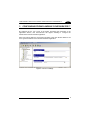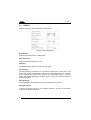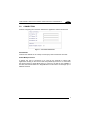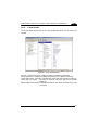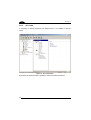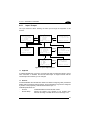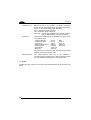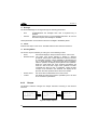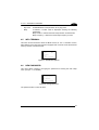
1
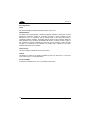
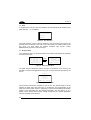
DL TCL™
User’s Manual
DL TCL™
USER'S MANUAL
DATALOGIC S.p.A.
Via Candini 2
40012 - Lippo di Calderara di Reno
Bologna - Italy
DL TCL™
This manual refers to software version 4.0 and later.
Ed.: 04/2004
ALL RIGHTS RESERVED
Datalogic reserves the right to make modifications or improvements without prior notification.
Datalogic shall not be liable for technical or editorial errors or omissions contained herein, nor for incidental or
consequential damages resulting from the use of this material.
Product names mentioned herein are for identification purposes only and may be trademarks and or
registered trademarks of their respective companies.
© Datalogic S.p.A. 2004
19/04/04
CONTENTS
1
1.1
1.1.1
GENERAL INFORMATION .......................................................................... 1
DL TCL™ ...................................................................................................... 1
DL TCL™ Operating Modes.......................................................................... 2
2
2.1
2.1.1
INSTALLATION............................................................................................ 3
Installing DL TCL™ onto the Terminal .......................................................... 3
DL TCL™ Installation Tree............................................................................ 4
3
3.1
3.2
3.3
3.4
3.5
3.6
3.6.1
3.7
3.8
3.8.1
3.8.2
3.8.3
3.9
3.9.1
CONFIGURING FROM DL MOBILE CONFIGURATOR™................................. 5
Device ........................................................................................................... 6
Connection.................................................................................................... 7
Emulation ...................................................................................................... 8
Advanced .................................................................................................... 10
Display ........................................................................................................ 11
Barcode Data Entry..................................................................................... 13
Barcode Formatting .................................................................................... 14
Printer ......................................................................................................... 16
Barcode....................................................................................................... 17
General Parameters.................................................................................... 18
Linear Codes............................................................................................... 21
2D Codes .................................................................................................... 22
Hosts........................................................................................................... 23
Key Mapper................................................................................................. 25
Mapping the Terminal Keys ........................................................................ 26
Changing Existing Sequences .................................................................... 27
Setting the Exit Emulation Key.................................................................... 28
4
4.1
4.2
4.2.1
4.2.2
4.2.3
4.3
4.3.1
4.3.2
4.3.3
4.4
4.4.1
4.4.2
4.4.3
4.5
CONFIGURING FROM TERMINAL............................................................ 29
Main Setup Menu........................................................................................ 30
Network Menu............................................................................................. 31
TCP/IP ........................................................................................................ 32
Radio........................................................................................................... 35
Connection.................................................................................................. 39
Emulation Menu .......................................................................................... 42
General Parameters.................................................................................... 42
Emulation VT100/VT220 ............................................................................. 43
Emulation 5250/3270 .................................................................................. 45
Device Menu ............................................................................................... 46
Input / Output .............................................................................................. 47
Display ........................................................................................................ 49
Beeper ........................................................................................................ 50
Info Terminal ............................................................................................... 51
iii
4.6
4.7
NEW Password........................................................................................... 51
FTP Server.................................................................................................. 52
5
5.1
DL TCL™ EXTENDED COMMANDS......................................................... 53
Proprietary Commands ............................................................................... 53
6
TERMINAL ERROR MESSAGES .............................................................. 55
iv
GENERAL INFORMATION
1
1.1
1
GENERAL INFORMATION
DL TCL™
Datalogic Terminal Emulation Client (DL TCL™) is a software providing VT100,
VT220 and IBM5250/3270 Telnet terminal emulation on Datalogic RF portable
terminals having an hardware architecture based on the DOS operating system.
If some parameters of the DL TCL™ configuration, defined and downloaded through
the DL Mobile Configurator™ Enterprise 2 (see DL Mobile Configurator™ Enterprise
2 User’s Manual for details), must be modified, it is possible to define their new
values directly from the terminal. In particular, a series of multi-setup menus allows:
- managing the scanner parameter;
- selecting 6 different fonts, plus one custom;
- managing beeper and backlight;
- logging events;
- autologin;
- relocating lines;
- managing different scrolling modes;
- managing the printer through electrical or IrDA interface;
- managing the connection to specific Hosts.
In addition, the user may also configure the main parameters of the following radio
types:
- Cisco 340 / 350 (IEEE 802.11b)
- Lucent / Artem (IEEE 802.11b)
- Symbol 11 Mb (IEEE 802.11b)
- Symbol 2 Mb (IEEE 802.11)
- Proxim 7400 (Open Air), available only for F7400 terminals
DL TCL™ satisfies all the connection modes required by your application.
It supports the Multi-Host functionality through which it may connect to a Host chosen
from a list, generated by the DL Mobile Configurator™ Enterprise program, of up to 5
Hosts.
Furthermore, in association with the DL Keep Connecting™ software package (see
the DL Keep Connecting™ User’s Manual for details), the terminal loading DL TCL™
can try a connection up to 4 PCs communicating with a remote Host. Once
connected to one of these PCs (Keep Connecting PC), the terminal can manage
multiple sessions and define a complete configuration through the multi-level setup
menu. In addition, the configuration can be set from the remote host and saved to
one or more files to be transmitted to the terminals via radio by using the FTP
protocol.
1
DL TCL™
1
1.1.1
DL TCL™ Operating Modes
DL TCL™ can be used for radio transmission with an Host or with a "Keep
Connecting" PC which is connected to a remote Host through a network connection:
-
Direct Host Mode
Keep Connecting (KC) Mode
In "Direct Host Mode" DL TCL™ runs on an RF terminal in VTxxx or IBM5250/3270
Telnet emulation which communicates via radio with a Host PC selected from a list of
up to 5 Hosts (Multi-Host functionality). If the list contains just a single Host, simply
press the terminal ENTER key to directly connect to it.
The terminal can be configured by setting the DL TCL™ configuration menus.
Figure 1 - Direct Host Mode
In "KC Mode" DL TCL™ interacts with the DL Keep Connecting™ installed in a
"Keep Connecting" Host PC communicating with a remote Host by means of a
network connection (refer to the related manual for details). The configuration files
can be saved and sent via radio to the terminal loading the FTP protocol. The
programs required for terminal remote configuration and its radio transmission are
provided within the DL Mobile Configurator™ Enterprise 2 package.
KC Host PC
Figure 2 - Keep Connecting Mode
2
INSTALLATION
2
2.1
2
INSTALLATION
INSTALLING DL TCL™ ONTO THE TERMINAL
Once the DL Mobile Configurator™ Enterprise 2 has been installed (see relevant
manual), it is possible to set and configure the DL TCL™ application and download
the related files onto your terminal.
Configuration Tree
Figure 3 – DL Mobile Configurator™ Enterprise 2 Main Window
For a correct and complete downloading, you must define the parameters available in
the configuration tree. In particular you must set the “Download Selection” parameter
to DL TCL™ for downloading this application.
Once you have set all the parameters required by your DL TCL™ application, it is
necessary to enable the communication between the DL Mobile Configurator™
Enterprise 2 and the terminal by following one of the procedures given below:
-
Connection through the RS232 port:
From the DOS prompt run the command DS [Bx], where x is one of the following
baud rate speeds:
5 = 9600 bps
6 = 19200 bps
7 = 38400 bps (default speed of the DTPS communication protocol)
8 = 57600 bps
9 = 115200 bps (default speed of the DL Mobile Configurator™ Enterprise 2)
-
Connection through Cradle:
Extract the terminal from its cradle, then, from the DOS prompt run the
command DC [Bx], where x is one of the following baud rate speeds:
5 = 9600 bps
6 = 19200 bps
7 = 38400 bps (default speed of the DTPS communication protocol)
8 = 57600 bps
9 = 115200 bps (default speed of the DL Mobile Configurator™ Enterprise 2)
After setting the required baud rate, insert the terminal back in the cradle and
the message “Start Server...” will appear on the display.
3
DL TCL™
2
Once the communication between the terminal and DL Mobile Configurator™
Enterprise 2 has been enabled, it is possible to start the downloading procedure by
clicking on the
2.1.1
icon available on the program toolbar.
DL TCL™ Installation Tree
Once the program has been installed correctly onto the terminal, all files dealing with
the program management will be placed into the following terminal directories:
C>
---+-|
+-|
+--
RF
TN
REMCONF
Figure 4 - Installation Tree
The RF directory contains all files dealing with the radio management. The file name
and dimension change according to the radio type installed on the terminal.
The TN directory contains the emulation program file Telxxxx.exe where:
xxxx = 9648 corresponds to Viper™ 48-key Models
9632 corresponds to Viper™ 32-key models
9700 corresponds to Rhino™ LCD
9700V corresponds to Rhino™ VFD
8600 corresponds to Kyman™
7400 corresponds to F7400
This directory also provides all configuration files:
-
HOST.ini: terminal parameters and address of the Hosts the terminal can be
connected to;
-
TCL.ini: terminal parameters (scanner, keyboard, font) and address of the KC PC
the terminal is connected to;
-
Socket.cfg: terminal TCP/IP parameters (IP address, subnet, gateway, dns);
Key.map: keyboard mapping parameters (optional).
The REMCONF directory contains all files defining the "KC Mode" (see the DL Keep
Connecting™ User's Manual for details).
To guarantee a correct remote configuration of the terminal, it is necessary to respect
the structure of the NEWAUTO.bat file installed on the terminal. The corruption or
omission of this structure may cause a wrong configuration downloading.
4
CONFIGURING THROUGH DL MOBILE CONFIGURATOR™ ENTERPRISE 2
3
3
CONFIGURING FROM DL MOBILE CONFIGURATOR™
By selecting the DL TCL™ item in the Select download type parameter of the
Application branch, new sub-branches will appear allowing to configure the
DATALOGIC terminal emulator application.
Each new branch within the work area (right side) of the main window allows to set
some general variables of the terminal emulation application.
Figure 5 – DL TCL™ Settings
5
DL TCL™
3
3.1
DEVICE
It allows defining the main parameters of the terminal:
Figure 6 – Device Parameters
Beep Duration
It defines the beep duration in milliseconds.
Beep Frequency
It defines the beep frequency in hertz.
Key Beep
It enables/disables a beep emission at any key press.
Out of Range
It allows signalling if a terminal is out of the area covered by the Access Point. If set
to Auto the terminal automatically signals if during data transmission it is out of the
area covered by the Access Point. If set to On no automatic control is enabled;
indeed, the terminal signals this condition only if the user tries to transmit data from
an uncovered area.
Auto Backlight
It enables/disables the backlight each time a keyboard key is pressed.
Backlight Timeout
It defines the timeout (secs.) for the backlight activation. As soon as the timeout
expires, the backlight is disabled.
6
CONFIGURING THROUGH DL MOBILE CONFIGURATOR™ ENTERPRISE 2
3.2
3
CONNECTION
It allows configuring the connection between the application and the remote host:
Figure 7 – Connection Parameters
KCn Name/IP
It defines the address for the 4 Keep Connect (KC) Host PCs listed in the mask.
Enable Multiple Session
It defines the type of connection to be used by the terminal to interact with
applications running on the remote Host and provided by the KC PC. If unchecked,
the terminal works in Single Mode trying to connect to the first KC PC available. If
checked, the terminal works as in Single Mode but in this case it can manage up to 4
different sessions.
7
DL TCL™
3
3.3
EMULATION
It allows defining the emulation parameters:
Figure 8 – Emulation Parameters
Device Name
It defines the name of the terminal performing the connection.
Password
It defines the password to type for entering the DL TCL™ setup.
Auto Run
It enables/disables the terminal automatic connection on startup of DL TCL™ or on
closure/connection failure.
Log File
It enables/disables the event log to track the events.
Upper Case
It enables/disables the conversion of all barcode data and keyboard digits to upper
case characters.
Add CR to LF
If checked, it adds the [CR] or [CR]+[LF] characters to the data format when pressing
the [Enter] key on the keyboard.
8
CONFIGURING THROUGH DL MOBILE CONFIGURATOR™ ENTERPRISE 2
3
Del to BS
It enables/disables the delete command when pressing the Backspace (BS) key on
the terminal keyboard.
Local Echo
It enables/disables the terminal Local Echo.
VT Answer Back
It defines the answer to be transmitted by the emulation program to the Host. It is
possible to customize a string of characters to be transmitted as answer; otherwise
you may send a part or the whole IP[n] or MAC[n] address.
Custom VT Answer Back
It allows defining the character string to be transmitted as answer when the VT
Answer Back parameter is set to Custom.
Reset Mode
It is available only for IBM terminal emulations. It defines the activation of the Reset
button when the data transmission from Host is blocked. If set to Manual the Reset
button has to be manually pressed, while setting to Auto the program will
automatically activate the Reset.
9
DL TCL™
3
3.4
ADVANCED
It allows to configure the advanced configuration features:
Figure 9 – Advanced Parameters
Start Row
It defines the line number (from 1 to 25) of the physical screen to be relocated on the
logical screen of the terminal.
Number of Rows
It defines the total number of rows to be relocated.
Destination Row
It defines the line number (from 1 to 25) of the terminal logical screen where the
relocated line(s) will be placed to.
Enable Keep Alive
If checked, it enables the Keep Alive functionality.
Keep Alive Timeout
It defines the time interval between the transmission of two Keep Alive packets.
10
CONFIGURING THROUGH DL MOBILE CONFIGURATOR™ ENTERPRISE 2
3.5
3
DISPLAY
It allows configuring the font type for the application.
Figure 10 – Display Parameters
Font Selection
A list of 7 font types is available, where six font types are fixed and one can be
customized by the user. For each font type is reported the maximum number of
characters (columns x lines). The defined font will be adopted as soon as the
terminal emulation is started. Once the emulation session is closed, the font selection
is restored to the default value. In the following table all fonts are listed according to
the terminal model:
Rhino™ LCD
Rhino™ VFD
Viper™
Kyman™
F7400 / F7400-E
Normal (64x12)
Small (80x25)
Medium (40x16)
Wide (40x12)
Bold (40x10)
Dbold (40x8)
Custom
Normal (25x8)
Small (32x16)
Medium (25x16)
Wide (16x12)
Bold (16x10)
Dbold (16x8)
Custom
Normal (24x20)
Small (30x20)
Dbold (15x13)
Double (15x16)
Xsmall (30x34)
Thin (24x26)
Custom
Normal (20x20)
Double (10x12)
Dbold (10x10)
Medium (16x15)
Xsmall (20x26)
Thin (16x20)
Custom
Normal (13x6)
Small (16x8)
Double (9x5)
Dbold (8x4)
Xsmall (24x8)
Thin (12x8)
Custom
Cursor Shape
It defines the shape of the cursor. Possible selections are Underline and Block.
11
3
DL TCL™
Scrolling Modes
Fixed
The terminal display is always locked at column 0 and row 0.
Quadrant Mode
The entire host screen (80x25) is divided in different quadrants, where each of them
defines the maximum number of characters (columns X lines) available for the
defined font set. In connection with an AS400 Host, if the active input field is
completely inside a quadrant, the display will be placed to this quadrant. While the
input fields that cross quadrant boundaries will result in a shift to the left or right of
the quadrant to include completely the field. For the VT emulation, where the field
concept is not included in the standard, the display will be placed in the same
quadrant where the cursor resides.
Center Cursor
The cursor will be maintained in the screen center.
Locked
The display is locked at the position specified by the Lock Row (from 1 to 25) and
Lock Column (from 1 to 80) parameters.
TCL Scroll Mode
If checked, it enables the DL TCL™ proprietary scroll mode.
12
CONFIGURING THROUGH DL MOBILE CONFIGURATOR™ ENTERPRISE 2
3.6
3
BARCODE DATA ENTRY
It allows configuring the entry of barcode data.
Figure 11 – Barcode Data Entry Definition
Laser Enable
It enables/disables the terminal laser for barcode reading. If disabled, the Barcode
branch (see par. 3.8) will not appear within the Configuration tree.
Barcode Termination Key
None
It means that no terminator is added to the data string
Enter
By selecting Enter, the terminator with ASCII value = 13 will be included in the output
data format.
Tab
By selecting Tab, the terminator with ASCII value = 08 will be included in the output
data format.
Field Exit
This special key is only available in connection with an AS400 Host. If selected, it is
included as terminator character in the output data format.
13
DL TCL™
3
Clear Before Scan
This special key is only available in connection with an AS400 host. If checked, it
clears the input field before sending the barcode read.
Baud Rate (available only for Rhino™)
This parameter is available only when the Rhino™ Barcode Input parameter is set to
Scanner (COM2/Scanner), Cordless-Card or Serial (COM1). Refer to DL Mobile
Configurator™ Enterprise 2 User’s Manual for further details.
It defines the baud rate.
Parity (available only for Rhino™)
This parameter is available only when the Rhino™ Barcode Input parameter is set to
Scanner (COM2/Scanner), Cordless-Card or Serial (COM1). Refer to DL Mobile
Configurator™ Enterprise 2 User’s Manual for further details.
It indicates the presence of a control bit in the communication protocol frame.
Data Bits (available only for Rhino™)
This parameter is available only when the Rhino™ Barcode Input parameter is set to
Scanner (COM2/Scanner), Cordless-Card or Serial (COM1). Refer to DL Mobile
Configurator™ Enterprise 2 User’s Manual for further details.
It indicates the number of bits composing the data packet of the communication
protocol frame.
Stop Bits (available only for Rhino™)
This parameter is available only when the Rhino™ Barcode Input parameter is set to
Scanner (COM2/Scanner), Cordless-Card or Serial (COM1). Refer to DL Mobile
Configurator™ Enterprise 2 User’s Manual for further details.
It indicates the number of stop bits the data packet of the communication protocol
frame.
3.6.1
Barcode Formatting
The Barcode Formatting area allows either selecting the codes to be read through an
input filtering mask or defining the output format of the code to be transmitted,
including possible code division into fields.
14
CONFIGURING THROUGH DL MOBILE CONFIGURATOR™ ENTERPRISE 2
3
Mode
If set to Recognition Only, it allows editing a single input filtering mask to select the
codes to be read. Click on the Edit button to open the following dialog box:
Figure 12 – Input Filtering Mask
Digit the matching string in the edit box by using the given syntax. The edited string
must have the same length as the one of the code to be formatted.
If set to Recognition and Transform, it allows editing up to 5 output filtering masks to
define the output format of the codes to be transmitted. Click on the New or Edit
button to open the following dialog box:
Figure 13 – Output Filtering Mask
In the first dialog box digit the matching string of the input filtering mask (see Figure
12), while in the second one define the string to be transmitted as output message.
The input and output strings must share the same length.
15
DL TCL™
3
3.7
PRINTER
It allows configuring the printer.
Figure 14 – Printer Setting
Communication
It defines the port to be used to send data from the terminal to the printer. The RS232
port indicates the electrical port, while IrDA indicates the optical port. The only
communication speed allowed for both ports is 38400 baud.
IBM AS400 Printer
It defines the parameters for the IBM AS400 printer. Unlikely the VT emulation, in
connection with an AS400 Host there is no protocol standard command to start the
printing process and it requires defining a byte for this purpose. The screen position
of the byte can be defined through the Printer Start Row (from 1 to 25) and Printer
Start Column (from 1 to 80) parameters, while its ASCII value has to be inserted in
the Flag Byte edit box (0 = disable IBM AS400 Printer).
Baud Rate
It sets the baud rate to communicate with the printer through the RS232 interface.
Parity
It indicates the presence of a control bit in the communication protocol frame.
Data Bits
It indicates the number of bits composing the data packet of the communication
protocol frame.
16
CONFIGURING THROUGH DL MOBILE CONFIGURATOR™ ENTERPRISE 2
3
Stop Bits
It indicates the number of stop bits the data packet of the communication protocol
frame.
3.8
BARCODE
The parameters available in the Barcode branch allow to configure the laser driver
parameters (SE 1200, SE122x and SE2223).
It is possible to select an item in left part of the screen and to set its proper
parameters on the right part.
Figure 15 – Barcode
17
DL TCL™
3
3.8.1
General Parameters
Code Length
It defines the minimum and maximum length of the code to be read.
Figure 16 – Code Length
Reading Security
By setting these parameters it is possible to guarantee a more precise code reading.
Figure 17 – Reading Security
Severity : 0 defines a more aggressive decoding, while 2 a more severe decoding
Redundancy : defines the number of times (plus 1) the code will be read before being
accepted
Quiet Zone: defines a standard or a narrow quiet zone. Do not enable this parameter,
if code symbologies other than EAN/UPC, Code 39 and Codabar are
enabled
Output Format
It defines the message format and transmission mode.
Figure 18 – Output Format
Code ID Type : selects the type of code identifier or no code identifier.
Send no Decode Character: if checked, it sends the “NR” after the laser timeout or
when releasing the scanner trigger.
Strip A from Code 32 : if checked, it allows stripping preamble A from each read
Code 32.
18
CONFIGURING THROUGH DL MOBILE CONFIGURATOR™ ENTERPRISE 2
3
Preamble/Postamble
It defines the preamble and postamble characters using the ASCII decimal value.
Figure 19 – Preamble/Postamble
For all parameters possible values are in the range 0-128, where 128 corresponds to
disabled.
Reading Feedback
It defines the type of indicator signaling that the code has been decoded.
Figure 20 – Reading Feedback
Decode Beep Tone : defines the beep tone.
Good Reading LED : if checked, it enables the green LED on successful decoding.
Laser Control
It defines the management of the terminal laser.
Figure 21 – Laser Control
Laser Time Out : defines the laser timeout in steps of 0.5 seconds (for ex., 0 = 0.5 s;
7 =4 s).
Aiming Time : defines the aiming time in steps of 0.25 seconds (for ex., 7 = 1.75 s);
0 = disabled.
19
DL TCL™
3
Always On : if checked, it allows the scanner to read even if the DS function has not
been called (for diagnostic purpose only).
SW Control : if checked, it allows the scanner to read even if the trigger is not
pressed (for diagnostic purpose only).
Keyboard Emulation : if checked, it enables the keyboard emulation (for diagnostic
purpose only).
Booklet Menu : if checked, it enables the scanner programming through the Booklet
menu.
Booklet Menu Supported : if checked, it causes the driver to transmit unknown
booklet commands to the application for processing.
EAN/UPC Supplementals
It defines the supplemental 2 digits or 5 digits for the EAN/UPC symbology.
Figure 22 – EAN/UPC Supplemental
2 Digits : if checked, it adds 2 digits to the EAN/UPC code symbology.
5 Digits : if checked, it adds 5 digits to the EAN/UPC code symbology.
Auto-discriminate : if checked, it allows reading all EAN/UPC codes including those
with supplementals.
Supplemental Redundancy: if some of the EAN/UPC supplementals has been
enabled, it defines the number of times (plus 1) that an
EAN/UPC code without supplementals must be read
and decoded before being accepted. This ensures that
the defined supplementals will be not lost/ignored as
soon as the standard EAN/UPC code is read.
20
CONFIGURING THROUGH DL MOBILE CONFIGURATOR™ ENTERPRISE 2
3.8.2
3
Linear Codes
The Linear Codes branch lists all the code symbologies which can be read by the
terminal.
Figure 23 – Linear Code Selection
For each code symbology it is possible to define the following parameters:
Decoding Enable: if checked, it enables the decoding of the specific symbology.
Check Digit Enable : if checked, it enables the check digit for the specific symbology.
Check Digit TX Enable : if checked, it transmits the check digit for the specific
symbology.
Minimum/Maximum Length : it defines the minimum and maximum length of the code
to be read.
21
DL TCL™
3
3.8.3
2D Codes
If configuring a terminal supporting the SE2223 driver, it is possible to read 2D
codes.
Figure 24 – 2D Code Selection
By selecting the desired code it is possible to select the related parameters.
22
CONFIGURING THROUGH DL MOBILE CONFIGURATOR™ ENTERPRISE 2
3.9
3
HOSTS
It allows defining the configuration of up to 5 Hosts to which DL TC™ can be
connected.
Figure 25 – Hosts
By clicking on the
button from the program Tool bar, it is possible to add a
new Host to the list and configure its parameters:
Figure 26 – Host Configuration
23
3
DL TCL™
Host Profile
It defines the logical name to be assigned to the current Host.
Host Name / IP
It defines the address to be used by the terminal when connecting to the Host PC.
Host Port
It defines the TCP/IP port to be used by the terminal for connection to the Host PC.
Emulation Type
It defines the type of emulation to be run on the terminal.
Enable Custom
If checked, it allows defining the Negotiation String.
Negotiation String
It defines the string transmitted to the Host to communicate the emulation supported
by the terminal.
Login Prompt
It defines the login prompt received from the Host.
Login Answer
It defines the value of the login.
Password Prompt
It defines the password prompt received from the Host.
Password Answer
It defines the value of the password.
Login Termination Key
It defines the character sent as terminator of the login field.
Command Prompt
It defines the command prompt received from the Host.
Command Answer
It defines the value of the command.
24
CONFIGURING THROUGH DL MOBILE CONFIGURATOR™ ENTERPRISE 2
3
The
button available on the program Tool bar allows deleting the selected
Host from the list.
3.9.1
Key Mapper
For each defined Host it is possible to use the “key mapper” utility to reconfigure the
terminal keyboard.
In this way, it is possible to map the most frequently used character combinations
into single key clicks.
The keyboard simulator shown in the work area (right side) of the main window
displays the keyboard layout of the terminal being configured.
The following example shows the Viper™ 48 keys using the 5250 emulation type:
Figure 27 – Keyboard Mapper
The keyboard simulator is displayed according to the choices made so far in terms of
Device Type and Emulation type. The terminal emulation parameter is available in
the Host branch (see par. 3.9), while the Device Type one can be defined in the
Terminal Configuration\Device Type branch (see DL Mobile Configurator™
Enterprise 2 User’s Manual for details).
25
DL TCL™
3
The table next to the keyboard graphical layout list all the defined key mappings.
In particular, the “Virtual Sequence” column shows the key sequence to be mapped,
while the “Physical Key” column displays the terminal physical key mapping the key
sequence.
The Key Mapping can be managed through the New, Edit and Delete buttons.
The Exit Emulation Key edit box shows (if defined) the mapped terminal key and can
be managed through the Map and Restore buttons.
Mapping the Terminal Keys
The key mapping process is very easy. Click on the New button to display the
following mask:
Figure 28 – Mapping a Virtual Sequence
First create the key sequence to be mapped by clicking on the button(s) of the
keyboard simulator. Whenever the mouse passes over a button this is
yellow-highlighted. Once selected, its borders turn to yellow and the corresponding
key is stored in the General Virtual Sequence edit box positioned in the right part of
the screen. The Additional virtual keys drop-down window under the Keypad
Simulator allows selecting additional virtual function keys (for VT emulation only) and
characters to be used for creating escape sequences.
26
CONFIGURING THROUGH DL MOBILE CONFIGURATOR™ ENTERPRISE 2
3
Then, click on the Next button to define the mapping terminal key. In this case,
whenever the mouse passes over a button this is red-highlighted. Once selected, its
borders turn to red and the corresponding key is stored in the Physical Key to Press
edit box.
The Clear button available in the mask deletes all characters defined within the
Generated Virtual Sequence edit box, while the Undo button restores the previously
defined sequence , if any, in both the edit boxes.
Finally, save the defined key mapping. It will be then listed in the Virtual
Sequence/Physical Key columns and the program is ready to start a new mapping
procedure.
Examples
The following mapping examples refer to the keyboard of the Viper™ 48 Key terminal
using the 5250 emulation type.
Function
Key/Sequence to Map
Mapping Key/Sequence
(yellow highlighted)
(red highlighted)
A
FUNC + SPACE
CTRL + T
0x1B + 4F + 50
B
SPACE
ESC
Q
Map “A” key to “B” key
Map “Tab” to “Space” key
Map “Field Exit” to “Esc” key
Map “F1” to “Q” using
escape sequence
Changing Existing Sequences
To change or delete an existing key sequence, click over a sequence listed within the
table and click on the
or
button.
The Edit button opens the mask (see Figure 28) where changing the key mapping
specifications.
The Delete button deletes the selected sequence from the list within the table.
27
DL TCL™
3
Setting the Exit Emulation Key
The Exit Emulation Key is a special key allowing to exit the terminal emulation
application. For this reason a special command has been introduced to map this key.
By default the used function key is F10.
To configure the Exit Termination key, position the cursor in the lower part of the
screen labelled “Exit Emulation Key” and click on the
button.
The following mask will be displayed:
Figure 29 – Mapping the Exit Emulation Key
Click on the desired button of the keyboard simulator. Whenever the mouse passes
over a button this is green-highlighted. Once selected, its borders turn to green and
the corresponding key is stored in the Physical Key to Press edit box.
Then, save the defined key mapping. It will be then listed in the Exit Emulation Key
edit box. To delete the current Exit Emulation key press the
28
button.
DL TCL™ EXTENDED COMMANDS
4
4
CONFIGURING FROM TERMINAL
Once the DL TCL™ application and configuration files have been downloaded onto
the terminal by using the DL Mobile Configurator™ Enterprise 2 program, it is
possible to change the value for most of the defined parameters directly from the
terminal. This operation is suggested when modifying a few parameters. If you need
to change most of the downloaded configuration, we advise to use the DL Mobile
Configurator™ Enterprise 2 program (refer to the relevant manual for further details).
To change the configuration from the terminal, a series of configuration menus is
available.
The main setup menu may be entered by following one of the given procedure:
-
when launching the DL TCL™ program for the first time, after terminal rebooting,
the program opening mask appears. By pressing the [ESC] key and inserting the
password (see Figure 31), the main setup menu will be displayed (see
Figure 32);
-
by pressing the “Exit Emulation Key” ([F10] is the default value) it is possible to
quit the terminal emulation at any time and display the opening mask and then
the main setup menu. This procedure requires exiting all sessions (see par.
4.2.3);
-
if no Host PC or KC PC is available for radio communication, the program
automatically displays the opening mask and then the main setup menu.
The following keys allow navigating within the configuration menus:
if pressed, it validates the selection. When navigating through
- [Enter]:
the menus it jumps to an upper level within the same page, or
jumps to another mask if the selection is displayed in several
pages.
-
[Numeric Keys]: if pressing the key corresponding to the number next to each
option, it is possible to select its value. If the selection is
exclusive or multiple, the defined option will be displayed in
reverse video. In case of more complex options, the numeric
key press opens another mask showing options belonging to
a lower level.
-
Arrow Keys:
if pressed, they increase / decrease a numeric value within a
defined range or scroll all available values of non-numeric
parameters.
The main setup menu is shared by all Datalogic RF portable terminals. Different
parameters will be signaled.
29
DL TCL™
4
4.1
MAIN SETUP MENU
At terminal boot, the following opening mask is displayed:
Datalogic Spa
DL - TCL
Terminal Emulation
ESC to Setup
ENTER to Connect
Figure 30 - Opening Mask
By pressing the [Enter] key it is possible to proceed with the connection to the Host
PC. The [ESC] key enters the main setup menu:
Datalogic SETUP
Terminal Emulation
Password Request
Password
Figure 31 - Entering Password
A password must be typed and the [Enter] key pressed to display the main setup
menu. The password can be modified after entering the main setup menu for the first
time. Its default value is "ls" (lower case characters).
Datalogic-MAIN
1/2
1) Network
2) Emulation
3) Device
4) Info Terminal
ENTER to Continue
Datalogic-MAIN
2/2
5) New Password
6) FTP-Server
7) Exit Setup
8) Exit to DOS
ENTER to Continue
Figure 32 - Configuration Menus
Two different masks display all configuration menus. It is possible to jump from the
first mask to the second one by pressing the [Enter] key.
30
DL TCL™ EXTENDED COMMANDS
4
As described in the introduction of this chapter, press the numeric key corresponding
to the number next to each option to select the desired menu:
1) Network:
2) Emulation:
3) Device:
4) Info Terminal:
5) New Password:
6) FTP-Server:
7) Exit Setup:
8) Exit to DOS:
4.2
allows configuring the TCP/IP parameters of the terminal,
Host PC, Keep Connecting PC and radio;
allows configuring the specific parameters of the
VT100/VT220 and IBM5250/3270 emulation and the debug
procedure;
allows configuring the parameters managing the terminal
peripherals, such as scanner, keyboard, display and
beeper;
returns information about the terminal and the DL TCL™
software, such as Bios version, DL TCL™ emulation
version, MAC address of the radio card;
allows setting a personalized password to enter the main
setup menu;
activates the terminal for loading the FTP protocol. Thus,
the terminal works as an FTP server;
allows exiting the main setup menu and jumping to the
opening mask;
allows exiting the program and returning to the DOS
prompt.
NETWORK MENU
This menu allows configuring the terminal TCP/IP and radio parameters and setting
the terminal connection to either the first Host PC of the Multi-Host list (see par. 1.1)
or a KC PC (see the DL Keep Connecting™ User's Manual for details).
Datalogic - SETUP
Network Settings
1) TCP/IP
2) Radio
3) Connection
ENTER to Continue
Figure 33 - Network Menu
31
DL TCL™
4
4.2.1
TCP/IP
If selecting this submenu, the following masks appear allowing to define the IP
parameters related to the terminal.
Datalogic - SETUP
Network Settings
1) TCP/IP
2) Radio
3) Connection
ENTER to Continue
"1"
Datalogic - SETUP
Network TCP/IP 1/2
1) IP Address
2) Subnet Mask
3) Gateway Address
ENTER to Continue
[ENTER]
[ENTER]
Datalogic - SETUP
Network TCP/IP 2/2
4) DNS Address
5) Device Name
ENTER to Continue
Figure 34 - TCP/IP Diagram
IP Address
The IP Address may be defined either manually (static), through DHCP (Dynamic
Host Configuration Protocol) or through BOOTP (Bootstrap Loader):
Datalogic - SETUP
Network IP Address
1) Static
2) Enable DHCP
3) Enable BOOTP
ENTER to Continue
Figure 35 - ID Address Selection
When defining the address manually (Static selection), the following mask appears:
Datalogic - SETUP
Network IP Address
- Static IP Address:
ENTER to Continue
Figure 36 – Defining Static IP Address
32
DL TCL™ EXTENDED COMMANDS
4
The IP Address value must respect the xxx.yyy.www.zzz structure, where x, y, w and
z value is in the range 0-255. After address selection and validation through the
[Enter] key, you will return to the first TCP/IP mask where the Static option is
displayed in reverse video. In case of wrong address definition, the terminal will not
proceed with the configuration.
Since the DHCP and BOOTP option have an exclusive selection, they do not open a
further mask.
Subnet Mask
The terminal subnet mask is to be set when a fixed address has been defined. Its
value must respect the xxx.yyy.www.zzz structure, where x, y, w and z are in the
range 0-255.
Datalogic - SETUP
Network TCP/IP
- Subnet Mask:
ENTER to Continue
Figure 37 - Subnet Mask
Gateway
The definition of the Gateway IP address must respect the xxx.yyy.www.zzz
structure, where x, y, w and z are in the range 0-255:
Datalogic - SETUP
Network TCP/IP
- Gateway Address:
ENTER to Continue
Figure 38 - Gateway Mask
33
DL TCL™
4
DNS
The definition of the DNS IP address must respect the xxx.yyy.www.zzz structure,
where x, y, w and z are in the range 0-255:
Datalogic - SETUP
Network TCP/IP
- DNS Address:
ENTER to Continue
Figure 39 - DNS Mask
Once the DNS has been configured, logical names substituting the IP address may
be used by the Host PC to identify the devices.
Device Name
This parameter allows assigning a name to the terminal performing the connection.
By inserting an (*) asterisk before the name (i.e.: "*Name"), the device name will
indicate the device name in the AS400 protocol (Variable: Device Name).
Datalogic - SETUP
Network TCP/IP
- Device Name:
ENTER to Continue
Figure 40 - Device Name Mask
This parameter can be used also for identification purpose when the terminal
communicates in KC Mode (see the DL Keep Connecting™ User's Manual for
details).
If the DNS parameter has been already set, it is not possible to define the Device
Name.
34
DL TCL™ EXTENDED COMMANDS
4.2.2
4
Radio
This submenu allows selecting the radio network the terminal belongs to. The
selected parameter acts upon the configuration files of the radio driver.
It is required to know the radio type installed on the terminal before
configuring these parameters.
NOTE
Datalogic - SETUP
Network Settings
1) TCP/IP
2) Radio
3) Connection
ENTER to Continue
"2"
[ENTER]
Datalogic - SETUP
Network Radio
1) Open Air
2) IEEE 802.11b
3) IEEE 802.11
ENTER to Continue
Figure 41 - Radio Menu
For each type of radio you can select the related radio card. Thus, modifying the
configuration file in the radio driver.
35
DL TCL™
4
Open Air Radio
Datalogic - SETUP
Network Radio
1) Open Air
2) IEEE 802.11b
3) IEEE 802.11
ENTER to Continue
"1"
[ENTER]
Datalogic - SETUP
Open Air Radio
1) Domain
2) Power Options
ENTER to Continue
"1"
Datalogic - SETUP
Open Air Radio
- Domain
[ENTER]
ENTER to Continue
"2"
Datalogic - SETUP
Open Air Radio
- Inactivity Minutes:
- Inactivity Seconds:
Figure 42 – Open Air Radio Settings
Radio
Card Model
Open Air
Settings
-
Proxim 7000
-
36
Domain = sets the network domain; this must match the
domain of the server or Access Point to be connected to.
It is a number in the range 0-15
Inactivity Seconds = sets the amount of inactivity time in
seconds after which the driver puts the station to sleep
Inactivity Minutes = sets the amount of inactivity time in
minutes after which the driver puts the station to sleep
DL TCL™ EXTENDED COMMANDS
4
IEEE802.11b Radio
Datalogic - SETUP
Network Radio
1) Open Air
2) IEEE 802.11b
3) IEEE 802.11
ENTER to Continue
"2"
[ENTER]
IEEE802.11b
1) Cisco
2) Lucent/Artem
3) Symbol
4) Out of Range ON
ENTER to Continue
"2"
Datalogic - SETUP
Lucent Wcard Radio
"1"
Datalogic - SETUP
Cisco Aironet Radio
1) SSID
2) Power Options
[ENTER]
ENTER to Continue
"3"
"1"
"2"
"ENTER"
Datalogic - SETUP
Cisco Aironet Radio
Datalogic - SETUP
Lucent Artem Radio
"1"
- Wireless Network Name
"ENTER"
- SSID Net Name:
1) W-Card-11
2) ComCard-11
ENTER to Continue
ENTER to Continue
ENTER to Continue
"2"
"ENTER"
Datalogic - SETUP
Lucent Wcard Radio
1) Enable Std Pwr
2) Enable Enh Pwr
3) Disable Pwr Save
ENTER to Continue
Datalogic - SETUP
Cisco Power Options
1) PSP mode
2) CAM mode
3) FASTPSP mode
ENTER to Continue
Datalogic - SETUP
Artem ComCard Radio
- ComPoint Net Name:
"ENTER"
ENTER to Continue
"ENTER"
[ENTER]
Datalogic - SETUP
Artem ComCard Radio
1) Enable Pwr Save
2) Disable Pwr Save
ENTER to Continue
Datalogic - SETUP
Symbol 802.11b 11Mb
"1"
- ESS_ID Network Name:
ENTER to Continue
[ENTER]
Datalogic - SETUP
Symbol 802.11b 11Mb
1) ESS_ID
2) Power Options
ENTER to Continue
"2"
[ENTER]
"ENTER"
Datalogic - SETUP
Symbol 802.11b 11Mb
- Performance Index:
ENTER to Continue
Figure 43 – IEEE802.11b Radio Settings
37
DL TCL™
4
When configuring the radio, the "Out of Range" option (set [AUTO]) allows DL TCL™
to automatically signal if during data transmission a terminal is out of the area
covered by the Access Point. For all terminals this condition will be signaled by the
LED activation, while for Rhino™ terminal the signal is emitted by the beeper. If set
to [ON], it is possible to verify this condition only if trying to transmit from the terminal.
In all these cases, the following message is displayed:
OUT OF RANGE
Retry? ( Y/N )
Radio
Card Model
IEEE 802.11b Wi-Fi
Cisco 340/350
Settings
-
IEEE 802.11b Wi-Fi Lucent/ARTEM
W-Card 11 ComCard 11
-
IEEE 802.11b Wi-Fi
Symbol Spectrum
24 High Rate
38
-
SSID = sets the Service Set Identifier of the specific
wireless network
Power Options = specifies the Power Save Mode,
where CAM corresponds to Constant Awake Mode,
PSP to Power Save Mode and FASTPSP to Fast Power
Save Mode
Wireless Network Name = sets the Service Set
Identifier of a specific wireless network. When this
parameter is omitted, or is specified as an empty string
or as “ANY”, the station may connect to any network
Card Power Management = enables or disables the
terminal use of the Power Management. Specifying 2
enables Enhanced Power Management, specifying 1
enables the Standard Power Management, while
specifying 3 disables the Power Management
ESS ID = sets the Service Set Identifier of a specific
wireless network
Performance Index = selects the power saving mode by
inserting a number between 0 and 5, where 0 sets the
consumption of most power at maximum speed, and 5
sets the consumption of least power at minimum speed.
DL TCL™ EXTENDED COMMANDS
4
IEEE802.11 Radio
Datalogic - SETUP
Symbol 802.11 2Mb
Datalogic - SETUP
Network Radio
1) Open Air
2) IEEE 802.11b
3) IEEE 802.11
ENTER to Continue
"3"
[ENTER]
Datalogic - SETUP
Symbol 802.11 2Mb
"1"
1) ESS_ID
2) Power Options
ENTER to Continue
"2"
- ESS_ID Network Name:
[ENTER]
ENTER to Continue
[ENTER]
Datalogic - SETUP
Symbol 802.11 2Mb
1) Enable Pwr Save
2) Disable Pwr Save
ENTER to Continue
Figure 44 – IEEE802.11 Radio Settings
Radio
Card Model
Settings
IEEE 802.11
Symbol Spectrum 24
-
4.2.3
ESS ID = sets the Service Set Identifier or the specific
wireless network
Power Options = turns on or off the Power Management
Connection
The Connection submenu allows defining the address of Host PC or Keep
Connecting PC communicating with the terminal.
The communication can be performed with the first Host PC of the Multi-Host list (see
par. 1.1) or up to 4 different Keep Connecting PCs.
Datalogic - SETUP
Network Settings
1) TCP/IP
2) Radio
3) Connection
ENTER to Continue
Datalogic - SETUP
Network - Connection
"3"
[ENTER]
1) Host
2) Keep Connecting
ENTER to Continue
Figure 45 – Connection Settings
39
DL TCL™
4
Host
If configuring the Host PC, the communication will automatically enter the Direct Host
Mode (see par. 1.1.1 for details).
Datalogic - SETUP
- Host Name/IP Address:
- Host Port:
- Emulation:
Figure 46 - Host Selection
This mask requires to set the Host IP address or the Host name to be used by the
terminal when connecting to the Host PC and the TCP/IP port (default value is port
23). Then, you must select the desired emulation type (VT100, VT220,
IBM5250/3270) by means of the arrow keys.
Keep Connect
An IP address for the 4 KC Host PCs listed in this mask can be defined to guarantee
a terminal connection.
Datalogic - SETUP
Keep Connecting 1/2
1) KC1 Name / IP
2) KC2 Name / IP
3) KC3 Name / IP
ENTER to Continue
[ENTER]
Datalogic - SETUP
Network Radio
4) KC4 Name / IP
5) Multi Session OFF
[ENTER]
ENTER to Continue
Figure 47 - Keep Connect Menu
The Multi Session parameter selects the type of connection to be used by the
terminal to interact with applications running on a remote Host and provided by the
KC PC:
KC1 MODE 1
- SESSIONS a) Session 1
b) Session 2
c) Session 3
d) Session 4
ENTER: select ESC: Exit
Figure 48 - Applications Mask
This mask lists all sessions available on the KC PC. The desired session can be
selected by either using the arrow keys or pressing the key corresponding to the
letter next to each option. "Mode 1" appearing on top of this mask defines the session
number to be associated with the selected application. For this reason, up to 4
Modes can be defined. Each session usually corresponds to a specific application
which is emulated on the terminal.
40
DL TCL™ EXTENDED COMMANDS
4
The management of this feature depends on the selection of the Multi-Session
parameter:
-
Single Session:
-
Multiple Session: the Multi-Session option is set to on. The terminal works as in
Single Session but in this case it can manage up to 4 different
sessions (Mode 1, Mode2, Mode 3 and Mode 4) at the same
time. It is possible to switch from one application to another by
pressing the following keys in sequence:
[ALT][1] = Mode 1
[ALT][2] = Mode 2
[ALT][3] = Mode 3
[ALT][4] = Mode 4
By pressing [ALT][0] in sequence the program returns to the
Applications mask as in Single Session. In this case, the
selection of a new session causes the closure of the
substituted one while the other sessions remain active.
For Viper™ 48-Key Models and Rhino™ the key sequence
switching from one application to another is the following:
[ALT][B] = Mode 1
[ALT][C] = Mode 2
[ALT][D] = Mode 3
[ALT][E] = Mode 4
[ALT][A] = Returns to Application Mask as in Single Mode
the Multi-Session parameter is set to off and the terminal tries
to connect to the first KC PC available. First, it tries to connect
to KC HOST 1 and, if not available, to KC HOST 2..4. In case
of failure, the terminal will try to connect to the Host PC by
entering automatically the Direct Host Mode (see par. 1.1.1
for details). If even the Host PC cannot be found, the terminal
displays the opening mask allowing to start the configuration
or configuration again.
Once a KC PC is found, the terminal enters Mode 1 (only one
session is allowed) and starts working within the desired
application running on the remote Host the KC PC is
connected to.
By pressing the [ALT][0] keys in sequence the program
returns to the Applications mask allowing to change the
session the terminal is connected to. The current session is
signaled in reverse video within the list. Once a new session
is set, the current one is automatically disabled and the
terminal starts emulating a new application/application
session. If no change has been made, press [Enter] to return
to the current session.
41
DL TCL™
4
4.3
EMULATION MENU
This menu allows setting the parameters managing the terminal emulation:
Datalogic - SETUP
Emulation
1) General
2) VT100/VT220
3) 3270/5250
ENTER to Continue
Figure 49 - Emulation Menu
4.3.1
General Parameters
Datalogic - SETUP
Emulation
1) General
2) VT100/VT220
3) 3270/5250
ENTER to Continue
"1"
[ENTER]
Datalogic - SETUP
1) AutoRun OFF
2) TCP KeepAlive
3) DL-TCL Scroll ON
4) Log Enable OFF
ENTER to Continue
"2"
[ENTER]
Datalogic - SETUP
TCP KeepAlive
1) TCP KeepAlive OFF
2) Timeout
ENTER to Continue
"2"
[ENTER]
Datalogic - SETUP
KeepAlive Timeout
- Timeout:
ENTER to Continue
Figure 50 – General Settings
AutoRun
It enables/disables the terminal automatic connection at program startup or on
closure/connection failure. If enabled, the program enters the opening mask and after
3 seconds tries to connect to the PC automatically. Once connected, it is possible to
enter the main setup menu by pressing the [ESC] key before a 3 sec. timeout
expires.
TCL KeepAlive
It enables/disables TCL KeepAlive function. This function allows the terminal to send
a NOP (no operation) packet to the Host at regular intervals in order to maintain the
radio connection.
Even if the terminal goes into suspend mode it automatically wakes up after
the timeout interval to send the NOP packet.
42
DL TCL™ EXTENDED COMMANDS
4
KeepAlive Timeout
It defines the time interval (in seconds) between the transmission of two NOP
packets.
DL TCL Scroll
It enables/disables the DL TCL™ proprietary scroll mode. In particular,
the CTRL + Arrow sequence allows scrolling up, down, left and right; otherwise, it is
possible to activate other commands through the CTRL + key sequence (ex. for
DL 9600 Viper™ 48-key model: CTRL + C = break).
Log Enable
It enables/disables the event log to track the events. All data received and sent from
the Host PC are saved to the DLLOG.TXT file positioned in "C:\". In addition, a
snapshot feature has been provided to capture the terminal screen to be logged.
During connection it is always possible to capture screens by pressing the [FUNC][P]
keys in sequence (for Viper™ 32-key models the key sequence is [FUNC][2]). Each
captured screen is saved to the DLLOG1.TXT file positioned in "C:\".
4.3.2
Emulation VT100/VT220
Datalogic - SETUP
Emulation
1) General
2) VT100/VT220
3) 3270/5250
ENTER to Continue
"2"
[ENTER]
Datalogic - SETUP
Emulation VT 1/2
1) Local Echo OFF
2) Del to BS OFF
3) Enter CR + LF
ENTER to Continue
[ENTER]
Datalogic - SETUP
- Login Prompt:
"4"
- Login Answer:
ENTER to continue
[ENTER]
[ENTER]
[ENTER]
[ENTER]
Datalogic - SETUP
4) Host Login
5) Login Termination
6) Command Execution
7) Relocation Row
ENTER to continue
“6”
Datalogic - SETUP
Login Termination
1) ENTER
2) TAB
[ENTER]
ENTER to continue
[ENTER]
Datalogic - SETUP
- Password Prompt:
Datalogic - SETUP
- Command Prompt:
- Password Answer:
- Command Answer:
ENTER to continue
“5”
ENTER to continue
“7”
[ENTER]
Datalogic - SETUP
Rows Relocation
- Start Row:
- Number of Rows:
- Destin. Rows:
ENTER to continue
Figure 51 – VT100/VT220 Emulation Settings
43
4
DL TCL™
Local Echo
It enables/disables the terminal Local Echo.
Del to BS
It enables/disables the delete command when pressing the Backspace (BS) key on
the terminal keyboard.
Enter CR + LF
It selects the CR or CR+LF characters to be added to the data format when pressing
the [Enter] key on the keyboard.
Host Login
It enables/disables the automatic login. In VT emulation, for the login and the
password request the user must specify the prompt received from the host and insert
the value of the login and password answer in the corresponding fields. It is also
required to specify the character sent as terminator of the Login field.
Login Termination
It selects the character to be sent as terminator of the login field.
Command Execution
It enables/disables the automatic execution of a command. In VT emulation, for the
command request the user must specify the prompt received from the host and insert
the value of the command answer in the corresponding fields.
Relocation Row
It enables/disables the relocation of one or more rows. The user can relocate one or
more lines from the physical screen of the host application to the logical screen of the
terminal. The parameters requested to activate this feature are:
Start Row: line number of the physical screen from which the relocation starts;
Number of Rows: the total number of rows to be relocated;
Destination Row: line number of the terminal logical screen where the relocated
lines will be placed.
44
DL TCL™ EXTENDED COMMANDS
4.3.3
4
Emulation 5250/3270
Datalogic - SETUP
Emulation
1) General
2) VT100/VT220
3) 3270/5250
ENTER to Continue
“2”
"3"
[ENTER]
[
Datalogic - SETUP
5250/3270 1/2
1) Host Login
2) Command Execution
3) Relocation Rows
ENTER to Continue
“1”
[ENTER]
[ENTER]
[ENTER]
Datalogic - SETUP
- Command Prompt:
Datalogic - SETUP
- User:
- Command Answer:
- Password:
ENTER to continue
[ENTER]
ENTER to continue
“3”
Datalogic - SETUP
5250/3270 2/2
AS400 Printer
Reset Mode MANUAL
4)
5)
ENTER to Continue
“4”
[ENTER]
Datalogic - SETUP
AS400 Printer
- Row Position:
- Col Position:
- Flag Byte:
ENTER to continue
[ENTER]
Datalogic - SETUP
Rows Relocation
- Start Row:
- Number of Rows:
- Destin. Rows:
ENTER to continue
Figure 52 – 5250/3270 Emulation Settings
Host Login
It enables/disables the automatic login. The user must specify a value for both the
user and the password answer fields.
Command Execution
It enables/disables the automatic execution of a command. In VT emulation, for the
command request the user must specify the prompt received from the host and insert
the value of the command answer in the corresponding fields.
Relocation Row
It enables/disables the relocation of one or more rows. In this option the user can
relocate one or more lines from the physical screen of the host application to the
logical screen of the terminal. The parameters requested to activate this feature are:
Start Row: line number of the physical screen from which the relocation starts;
Number of Rows: the total number of rows to be relocated;
Destination Row: line number of the terminal logical screen where the relocated
lines will be placed.
45
DL TCL™
4
AS400 Printer
It defines the parameters for the IBM AS400 printer. Unlikely the VT emulation, the
AS400 emulation has no protocol standard command to start the printing process
and it requires defining a byte for this purpose. Specify the screen position of the byte
through “Row Position” and “Col Position”, and its ASCII value in “Flag Byte”.
Reset Mode
It enables/disables the activation of the Reset button when the data transmission
from Host is blocked. If set to Manual the Reset button has to be manually pressed,
while setting it to Auto the program will automatically activate the Reset.
4.4
DEVICE MENU
This menu allows setting the parameters managing the terminal display, scanner,
keyboard and beeper.
Datalogic - SETUP
Device Settings
1) Input/Output
2) Display
3) Beeper
ENTER to Continue
Figure 53 - Device Menu
46
DL TCL™ EXTENDED COMMANDS
4.4.1
4
Input / Output
The Input submenu allows defining the data input through the keyboard or the
scanner.
Datalogic - SETUP
Device Settings
1) Input/Output
2) Display
3) Beeper
ENTER to Continue
“3”
[ENTER]
Datalogic - SETUP
Printer Settings
1) RS232 Port
2) IRDA Port
ENTER to continue
"1"
[ENTER]
[
Datalogic - SETUP
Input/Output Options
1) Keyboard
2) Scanner
3) Printer
ENTER to Continue
“1”
[ENTER]
Datalogic - SETUP
Keyboard Options
1) Uppercase OFF
ENTER to Continue
“2”
[ENTER]
Datalogic - SETUP
Scanner Options 1/2
1) Scanner ON
2) Decode Beep
3) Term Key
ENTER to continue
[ENTER]
ENTER to continue
“3”
Datalogic - SETUP
Term. Key 1/2
1) NONE
2) ENTER
3) TAB
ENTER to continue
Datalogic - SETUP
Scanner Options 2/2
4) Code Type
5) Clrbefore SCAN OFF
[ENTER]
[ENTER]
Datalogic - SETUP
Term. Key 2/2
4) FIELD EXIT
ENTER to continue
Figure 54 - Input / Output Options
Keyboard
It enables/disables the conversion of all barcode data and keyboard digits to upper
case characters. If disabled, the barcode data keeps its original format and the
normal keyboard functioning is not changed.
Scanner
It enables/disables the terminal laser reader and allows configuring other parameters
dealing with the terminal reading features. These parameters may be also configured
by means of the proprietary commands described in par. 5.1.
Available parameters are:
-
Scanner
enables/disables the terminal laser reader.
Decode Beep:
defines the beeper tone duration to be emitted upon
barcode decoding. Possible values are in the range 0-31.
47
4
DL TCL™
-
Terminator key:
defines the key to be pressed to include a terminator
character in the output data format. Possible selections are:
None = no terminator added to the data string
Enter = terminator ASCII value is 13
Tab = terminator ASCII value is 08
Field Exit = special key available in the AS400 emulation
(only for IBM5250/3270 terminal emulation).
-
Code Type:
opens further masks listing all available code types for the
connected terminal:
Code 39 standard
UPC-A
MSI
Code 39 full ASCII
UPC-E
Code 11
Code 39 CIP
EAN-8
Code 93
Italian Pharmaceutical
EAN-13
PDF-417
Interleaved 2/5
Codabar
Micro PDF
Industrial 2/5
Code 128
Matrix 2/5
EAN-128
The selection of a code type within the mask is signaled by
displaying the code in reverse video.
-
Clrbefore SCAN:
This “Clears Before Scan” key is only available in
connection with an AS400 Host. It defines whether clearing
the input field before sending the code barcode read.
Printer
It defines the type of printer port through which sending data from the terminal to the
printer.
48
DL TCL™ EXTENDED COMMANDS
4.4.2
4
Display
The Display submenu allows defining the font dimension to be used for terminal
emulation and the backlight management.
Datalogic - SETUP
Device Settings
1) Input/Output
2) Display
3) Beeper
ENTER to Continue
"2"
[ENTER]
[
Datalogic - SETUP
1) Font Selection
2) Backlight
3) Cursor
4) Scrolling Modes
ENTER to Continue
“1”
Datalogic - SETUP
Display Fonts 1/2
1) Normal (64x12)
2) Small (80x25)
3) Medium (40x16)
ENTER to Continue
[ENTER]
“3”
“2”
[ENTER]
[ENTER]
[ENTER]
Datalogic - SETUP
Display Cursor
1) Block
2) Underline
Datalogic - SETUP
Display Backlight
1) Auto ON
2) Timeout
ENTER to continue
ENTER to continue
Datalogic - SETUP
4) Wide (40x12)
5) Bold (40x10)
6) DBold (40x08)
7) Custom Font
ENTER to continue
“4”
[ENTER]
Datalogic - SETUP
1) Fixed
2) Quadrant Mode
3) Center Cursor
4) Locked
ENTER to continue
Figure 55 - Display Diagram
Font
A list of 7 font types is available, where six font types are fixed and one can be
customized by the user. For each font type is reported the maximum number of
characters (columns x lines). The defined font will be adopted as soon as the
terminal emulation is started. Once the emulation session is closed, the font selection
is restored to the default value. In the following table all fonts are listed according to
the terminal model:
Rhino™ LCD
Rhino™ VFD
Viper™
Kyman™
F7400 / F7400-E
Normal (64x12)
Small (80x25)
Medium (40x16)
Wide (40x12)
Bold (40x10)
Dbold (40x8)
Custom
Normal (25x8)
Small (32x16)
Medium (25x16)
Wide (16x12)
Bold (16x10)
Dbold (16x8)
Custom
Normal (24x20)
Small (30x20)
Dbold (15x13)
Double (15x16)
Xsmall (30x34)
Thin (24x26)
Custom
Normal (20x20)
Double (10x12)
Dbold (10x10)
Medium (16x15)
Xsmall (20x26)
Thin (16x20)
Custom
Normal (13x6)
Small (16x8)
Double (9x5)
Dbold (8x4)
Xsmall (24x8)
Thin (12x8)
Custom
49
DL TCL™
4
Backlight
The terminal Backlight is managed through the following parameters:
-
Auto:
enables/disables the backlight each time a keyboard key is
pressed.
-
Timeout:
defines the timeout (secs.) for the backlight activation. As soon as
the timeout expires, the backlight is disabled.
These parameters are not effective when the backlight is disabled by BIOS.
Cursor
It defines the shape of the cursor. Possible selections are Underline and Block.
Scrolling Modes
The screen may be scrolled by choosing one of the following modes:
-
Fixed:
-
Center Cursor:
the cursor will be maintained in the screen center.
Locked:
the display is locked at the position specified by the Lock Row
and Lock Column parameters.
the terminal display is always locked at column 0 and row 0.
Quadrant mode: The entire host screen (80x25) is divided in different
quadrants, where each of them defines the maximum number
of characters (columns X lines) available for the defined font
set. In AS400 emulation, if the active input field is completely
inside a quadrant, the display will be placed to this quadrant.
While the input fields that cross quadrant boundaries will
result in a shift to the left or right of the quadrant to include
completely the field. For the VT emulation, where the field
concept is not included in the standard, the display will be
placed in the same quadrant where the cursor resides.
4.4.3
Beeper
The Beeper submenu manages the beeper activation according to the terminal
functions.
Datalogic - SETUP
Device Settings
1) Input/Output
2) Display
3) Beeper
ENTER to Continue
Datalogic - SETUP
Beeper Options
1) Key Click OFF
2) Beep
"1"
Datalogic - SETUP
Beeper Options
- Beep Duration:
- Beep Frequency:
[ENTER]
ENTER to Continue
Figure 56 - Beeper Options
50
"2"
[ENTER]
DL TCL™ EXTENDED COMMANDS
-
4.5
4
Key Click:
enables/disables a beep emission at any key press.
Beep:
if selected, a further mask is displayed showing the following
parameters:
Beep Duration = defines the alarm beep duration in milliseconds.
Beep Frequency = defines the alarm beep frequency in hertz.
INFO TERMINAL
This menu shows information about the BIOS version, DL TCL™ emulation version,
MAC address of the radio the terminal is equipped with. It also show the terminal free
memory and the connected socket :
Bios:
DL-TCL V.
Rev.
Mac:
Free Memory:
Socket:
Enter to continue
Figure 57 - Info Machine Options
4.6
NEW PASSWORD
This menu allows creating or changing the password for entering the main setup
menu (see par. 4.1 for details).
Datalogic SETUP
Change Password
- New Password:
Enter to continue
Figure 58 - Change Password
The password value is case sensitive.
51
DL TCL™
4
4.7
FTP SERVER
The FTP server is supported by each terminal and allows both the KC mode
connection and file upload/download.
When the terminal works as an FTP server the following mask appears:
Datalogic FTP SERVER
Version:
Server IP Address:
You’re on Remote..
Figure 59 - FTP Server
An FTP client can be connected to the FTP server through the IP address displayed
on the terminal as showed in the figure above.
The FTP client connection is allowed if the "User" and "Password" parameters are
set as follows:
-
User = "Datalogic"
Password = "dlftp"
By pressing the [ESC] key the connection will be interrupted.
52
DL TCL™ EXTENDED COMMANDS
5
5.1
5
DL TCL™ EXTENDED COMMANDS
PROPRIETARY COMMANDS
The proprietary commands allows exploiting standard features performed by the
Datalogic portable terminals.
The following table lists all commands managing the barcode reading by
enabling/disabling the terminal laser reader or by selecting the barcode symbology to
be read:
Symbology
Codabar
Code 11
Code 128
Code 39
Code 39 CIP
Code 93
Interleaved 2/5
Italian pharmaceutical
EAN-13
EAN-8
EAN-128
MSI
UPC-A
UPC-E
Enable All
Disable All
Command
ESC$<0/1>a&
ESC$<0/1>b&
ESC$<0/1>c&
ESC$<0/1>d&
ESC$<0/1>e&
ESC$<0/1>f&
ESC$<0/1>g&
ESC$<0/1>h&
ESC$<0/1>i&
ESC$<0/1>l&
ESC$<0/1>m&
ESC$<0/1>n&
ESC$<0/1>o&
ESC$<0/1>p&
ESC$<0/1>x&
ESC$<0/1>y&
The <0/1> string indicates the two possible values, where 0 disables the option and 1
enables it.
Other commands are provided in the following table for the scanner and keyboard
management:
Function
Command
Enable keyboard only
Enable scanner only
Enable scanner and keyboard
Enable alphabetic digit
Enable numeric digit
Enable alphanumeric digit
Enable keyboard default
ESC[d1I$
ESC[d2I$
ESC[d0I$
ESC[d1I&
ESC[d2I&
ESC[d3&
ESC[d0I&
53
DL TCL™
5
The following table lists commands managing different terminal functions:
Function
Change beeper frequency
(<FFFFF>)
and
duration
(<DDDDD>)
Enable barcode formatting, if
configured
Disable barcode formatting, if
configured
Enable a customized alarm for
the defined period of time
(<SS>). During this period the
terminal is locked while its
beeper, LED and backlight are
activated at regular intervals.
Command
ESC[d0<FFFFF><DDDDD>*
ESC[d1*
ESC[d2*
ESC[d0<SS>#
Other commands are provided to change the font type run-time. After changing the
font type a new send mask process is suggested.
Font
Command
Font Normal
Font Double
Font Double Bold
Font Thin
Font Small
Font XSmall
Font Custom
ESC#a
ESC#b
ESC#c
ESC#d
ESC#e
ESC#f
ESC#g
54
TERMINAL ERROR MESSAGES
6
6
TERMINAL ERROR MESSAGES
During the terminal normal functioning some error messages may appear on the
display.
The following table lists and explains all error messages:
Error Message
Description
Error on Password
Connecting KC1…
A wrong password has been inserted.
The terminal is trying to connect to KC HOST
1. A similar message is also displayed when
trying connection to other KC Hosts.
Error ConnectSocket (2)
A DOS error occurred
Error ConnectSocket (3)
No memory to perform function
Error ConnectSocket (4)
Connection does not exist
Error ConnectSocket (5)
Protocol or mode not supported
Error ConnectSocket (7)
No host address specified
Error ConnectSocket (13)
The function timed out
Error ConnectSocket (14)
Unknown host has been specified
Error ConnectSocket (18)
Bad arguments
Error ConnectSocket (19)
The connection has been closed by peer
Error ConnectSocket (20)
The connection has been reset by peer
Error ConnectSocket (21)
Operation would block
Error ConnectSocket (22)
The descriptor has not been assigned
Error ConnectSocket (23)
No socket is available
Error ConnectSocket (24)
Bad parameter in call
Error ConnectSocket (26)
The connection has not been established
NetSocket Error
Connection has been reset
NetSocket Error(5)
Peer has closed connection
NetSocket Error(6)
Connection has been closed
SOCKET CLOSED
The TCP/IP socket is closed. This error is sent
after the "Error ConnectSocket" or "NetSocket
Error" if no connection is active.
Reset and free memory.
An error has occurred during memory
allocation. It is advised to reset the terminal.
Are you sure to save New The terminal prompts for confirmation before
Password? (Y/N)
saving a new password.
55
DL TCL™
6
Error Message
Parameters
changed.
changes? (Y/N)
Description
Save If exiting the main setup menu after changing
some parameters, the terminal prompts for
confirmation before updating the values.
Wait…(saving changes)
The terminal asks to wait while saving the new
configuration values.
WARNING! Default Parameters The configuration of specific parameters, such
changed. If you save you need as IP Address and Radio parameters, requires
to reboot. Save changes? (Y/N) the terminal reboot to be activated. By saving
the changes, all the new configuration values
will be saved and the terminal rebooted.
Changed. System will be The terminal is saving new data and it will be
reboot…
rebooted.
Connection closed by remote The connection has been terminated by the
host. Warning! Session Closed remote host.
by Remote Host.
NOT AVAILABLE CONNECTION The connection is not available because it has
been terminated by the remote host.
This message appears only when working in
Multi-Mode connection with a session still
active.
Error on GetSocket. Emulation A fatal error has occurred in the TCP/IP
aborted…
management. It is necessary to reset the
terminal.
Warning! Machine not enabled At startup the program did not find the required
to open *.INI file. Press any key configuration files.
to Continue.
Warning! Error on *.cfg file. An error has occurred on reading the
Press any key to Continue.
configuration files. One or more parameters
might not be configured correctly.
Host Disconnected…
This message appears only when the Autorun
If you want Escape press ESC parameter (Emulation menu) is enabled. It
else the System tries to signals that the terminal has been
Reconnect in about 3 seconds... disconnected from the Host PC or the session
has been terminated. It will try to reconnect
within 3 seconds…
If a new connection attempt is not required, it
may be skipped by pressing the [ESC] key.
56