1
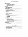
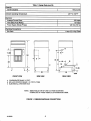
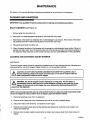
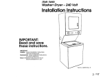
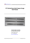
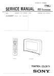
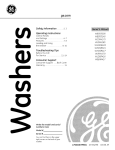
c
-
aSGD
lnstallation/service
Manual
ICE DISPENSER
DPP 230-Push-Button Operated
DPK 230-Key Operated (Optional)
DPC 230-Card Operated (Optional)
DPT 230-Token Operated (Optional)
Manual Part No. 161952801
OIMI Cornelius Inc.; 1995
January, 1995
Revised: October 25, 1995
TABLE OF CONTENTS
SAFETY INFORMATION
Page
....................................................
1
RECOGNIZE SAFETY INFORMATION ...............................
UNDERSTAND SIGNAL WORDS ....................................
FOLLOW SAFETY INSTRUCTIONS .................................
INTRODUCTION
...........................................................
1
3
SERVICE CORRESPONDENCE .........................................
GENERAL INFORMATION
3
5
TO THE USER OF THIS MANUAL .......................................
CLAIMS INSTRUCTIONS ..............................................
WARRANTY REFERENCE INFORMATION ...............................
DESIGN DATA ........................................................
INSTALLATION
5
5
5
5
7
SELECTING LOCATION ................................................
ELECTRICAL REQUIREMENTS .........................................
INSTALLATION ........................................................
INSTALLING ICE DISPENSER ......................................
FILLING DISPENSER ICE BIN HOPPER WITH ICE ....................
ADJUSTMENTS ...................................................
OPERATION ......................................................
MAINTENANCE
7
7
7
7
8
8
10
13
CLEANING AND SANITIZING ...........................................
DAILY CLEANING (SEE FIGURE 2) ..................................
CLEANING AND SANITIZING ICE BIN INTERIOR .....................
ADJUSTMENTS .......................................................
FILLING DISPENSER ICE BIN HOPPER ..................................
TROUBLESHOOTING
13
13
13
14
14
17.
NO ICE DISPENSED ...............................................
WARRANTY
17
24
1
1
..................................................
............................................................
...........................................................
......................................................
..............................................................
LIST OF FIGURES
FIGURE 1. DIMENSIONS/DRAIN CONNECTIONS .........................
FIGURE 2. DISPENSER COMPONENTS (PUSH-BUTTON MODEL SHOWN)
FIGURE 3.WIRING DIAGRAM ..........................................
FIGURE 4 . ICE DISPENSER ............................................
FIGURE 5. ELECTRICAL BOX ASS’Y ....................................
.
6
9
15
19
22
LIST OF TABLES
TABLE 1. DESIGN DATA ................................................
i
5
161952801
SAFETY INFORMATION
Recognize Safety Information
A
This is the safety-alert symbol. When you see this
symbol on our machine or in this manual, be alert to
the possibility of personal injury.
Follow recommended precautions and safe operating
practices.
Understand Signal Words
A signal word - DANGER, WARNING, OR CAUTION
is used with the safety-alert symbol. DANGER identifies the most serious hazards.
Safety signs with signal word DANGER or WARNING
are typically near specific hazards.
General precautions are listed on CAUTlON safety
signs. CAUTION also calls attention to safety messages in this manual.
A WARNING
A CAUTION
Follow Safety Instructions
Carefully read all safety messages in this manual and on your macnine safety signs. Keep safety signs in
good condition. Replace missing or damaged safety signs. Learn how to operate the machine and how to
use the controls properly. Do not let anyone operate the machine without instructions. Keep your machine in
proper working condition. Unauthorized modifications to the machine may impair function and/or safety and
affect the machine life.
1
161952801
Table 1. Design Data (cont’d)
Capacity:
I
Ice Bin Capacity
160 pounds
Ambient Operating Temperature
40’ F to 100’ F
Electrical:
Average Current Draw
Time Delay Fuse Rating
Power Supply (Single Phase)
~~
~~~~
2.5 Amps
15 Amps
120 VAC, 60 HZ
~~~~~
Plumbing Connections:
I
Bin Drain
1-inch O.D. Vinyl Tube
I
.
1
11.OE
T
41.13
24
I
A@
b f6
FRONT VIEW
V
-30-1
-30
-
9.56
REAR VIEW
SIDE VIEW
A CONDENSATE DRAIN 1/2 F.P.T.
B BIN AND STATION DRAIN 1 IN.VINYL TUBE
C ELECTRICAL JUNCTION BOX
NOTE: REMOVABLE TOP OF UNIT CUT FOR MOUNTING
CORNELIUS 30” WIDE VERTICAL EVAPORATOR CUBER.
FIGURE 1. DIMENSIONS/DRAINCONNECTIONS
161952801
6
11.25
GENERAL INFORMATION
TO THE USER OF THIS MANUAL
This Manual is a guide for installing and operating this equipment. Refer to Table of Contents for page location
of detailed information pertaining to questions that may arise during installation or operation of this equipment.
CLAlMS INSTRUCTIONS
Claims: In the event of shortage, notify the carrier as well as IMI Cornelius immediately. In the event of damage, not fy the carrier. IMI Cornelius is not responslble for damage occurring in transit, but will gladly
render ssistance necessary to pursue your claim. Merchandise must be inspected for concealed damage within 15 days of receipt.
b
WARRANTY REFERENCE INFORMATION
Warranty Registration Date
(to be filled out by customer)
,.
I
Unit Part Number:
Serial Number:
Install Date:
Local Authorized
Service Center:
DESIGN DATA
~~
~
Table 1. Design Data
Unit Model Numbers:
DPP 230 Push-Button Operated
DPK 230 Key-Operated (Optional), 161467-001
DPC 230 Card Operated (Optional), 161467-002
DPT 230 Token Operated (Optional), 1614671-000
I
Overall Dimensions:
I
Heiaht
Width
Depth
59-318 inches
30 inches
30 inches
Weights:
Dry Weight (No ice in ice bin Bin)
ShiDDina Weiaht
I
170 pounds
200 Dounds
5
161952901
INSTALLATION
This section of the manual covers installing the dispenser, preparing the dispenser for operation, and operating
the dispenser.
SELECTING LOCATION
1. Locate the Ice Dispenser in a cool shaded area close to a properly grounded and fused electrical outlet
with proper electrical requirements (see Table 1 Design Data).
2. Provide a suitable trapped open drain as close as possible to the area where the Ice Dispenser will be
installed. This may be an existing floor drain or a 1 1/4-inchtrapped open drain. All plumbing must be
installed according to National and local plumbing codes.
ELECTRICAL REQUIREMENTS
The electrical supply must be 120V 60 cycle, 1 phase and the unit must be properly grounded. ALL WIRING
MUST CONFORM TO NATIONAL AND LOCAL ELECTRICAL CODES. VOLTAGE MINIMUMS: 120V unit 103 volts minimum. REFER TO SERIAL PLATE FOR MINIMUM CIRCUIT AMPACITY AND MAXIMUM TIME
DELAY FUSE SIZE.
INSTALLATlON
INSTALLING ICE DISPENSER
1. To uncrate the Ice Dispenser, carefully remove the staples holding the crate to the bottom of the skid, then
lift the crate up off the Dispenser.
2.
Very carefully tip the Ice Dispenser over on it’s side and remove the four bolts holding the skid to the bottom of the Dispenser, then remove the skid.
NOTE: The leg kit, loose-shippedand found inside the Ice Dispenser, must be installed at this time.
3. Install the four legs in four corners of the Ice Dispenser base as shown in Figure 2.
4. Very carefullyset the Ice Dispenser in upright position on it’s legs in selected operating location. Make sure
the Ice Dispenser is leveled after placing in operating location.
5. Locate the ice storage bin drain hose (3/4-inch hose) located on back side of the Ice Dispenser
(see figure 1) and route it to to the open drain. The storage bin drains by gravity and the drain hose must
maintain a gradual slope to the drain for proper draining. The drain hose should be insulated to prevent
condensation from dripping from the hose. Condensation dripping from the drain hoses can cause serious
staining of carpeting or hardwood floors.
6. A separate drain line must be provided for the condensate drain (see figure 1). The parts bag inside the Ice
Dispenser contains a plastic 1/2- inch NPT to a 3/4-inch O.D. drain hose fitting that may be used to make
the condensate drain hose connection to the Ice Dispenser..
NOTE: Plumbing codes will not allow the ice storage bin drain hose and the condensate drain hose to
be tied together which could possibly cause water from the ice bin drain hose to “back up” Into the
condensate drain hose.
7
161952801
7. Using the condensate drain hose fitting referred to in preceding step 6, Install the fitting in the Ice
Dispenser.
8. Connect drain hose to the condensate drain hose fitting , then route drain hose to the open drain. The drain
hose should be insulated to prevent condensation from dripping from the hose. Condensation dripping from
the drain hoses can cause serious staining of carpeting or hardwood floors.
9. The ice bin hopper interior must be thoroughly cleaned prior to filling the ice bin hopper with ice in prepara-
tion for dispenser operation. Refer to CLEANING INSTRUCTIONS and thoroughly clean the ice bin hopper
interior.
FILLING DISPENSER ICE BIN HOPPER WITH ICE
WARNING: The ice bin hopper contains hazardous moving parts. The ice rotator is
automatically timed to start and move a short distance to break up ice in the ice bin. Do not
remove the ice bin hopper top cover without first disconnecting electrical power from the
dispenser.
IMPORTANT: The use of bagged ice, which has frozen into large chunks, can void the factory warrant&
The dispenser ice rotator is not designed to be an ice crusher. Use of large chunks of ice which may
“jam up” inside the ice bin hopper, may cause failure of the agitator motor and and may result in
damage to the inside of the ice bin hopper. If bagged ice will be used, it must be completely broken up
into small cube-sized pieces before being placed in the ice bin hopper.
Do not use hard-frozen ice. After ice has been removed from the freezer, allow ice to sit at room
temperature for approximately 1/2-hour before placing ice in the ice bin hopper. Ice to be used to fill
the ice bin hopper must be in the form of small cubes, chunklets, or cracked ice (DO NOT US€ FLAKE
OR CRUSHED ICE).
1. Make sure electrical power is disconnected from the dispenser.
2. Observing the preceding IMPORTANT note, fill ice bin hopper with small cubes, chunklets, or cracked ice.
3. Install ice bin hopper top cover.
ADJUSTMENTS
All adjustments require access to the inside of the electrical box assembly (see Figure 2). To gain entry to the
inside of the electrical box assembly, you must have the key to open the electrical box assembly front panel.
Unlock, then pull out and down on the electrical box assembly front panel to expose the MANUAUPORTION
CONTROL SWITCH the ICE PORTION SIZE ADJUSTMENT KNOB, and the time delay between dispensed ice
portions TIME DELAY ADJUSTMENT SCREW inside the electrical box assembly. Perform the following instructions to make pre-operation adjustments.
ual/Portion Control Switck
Inside the electrical box assembly, you will find a MANUAUPORTION CONTROL SWITCH. If it is
desired to dispense ice continuously when the dispenser is activated, place the MANUAUPORTION CONTROL
SWITCH in the “MANUAL” position.
If the MANUAUPORTION CONTROL SWITCH is placed in the “PORTION position, a set time of
approximately 1/2 to 20-seconds (adjustable) will be established for dispensing a portion of ice when the dispenser is activated (see Ice Portion Siire W t m e m .
Place the MANUAUPORTION CONTROL SWITCH in the desired mode of operation.
161952801
8
ELECTRICAL BOX
ASS'Y
FRONT PANEL
I
STATION TUB
.
GRILLE
\ /
a
FIGURE 2. DISPENSER COMPONENTS (PUSH-BUTTON MODEL SHOWN)
9
161952801
Ice Portion Size Adjustmeat
Located in the rear of the electrical box assembly, you will find the ICE PORTION SIZE ADJUSTMENT
KNOB. Turn the ICE PORTION SIZE ADJUSTMENT KNOB to the left (counterclockwise) for less ice
dispensed or turn the knob to the right (clockwise) for more ice dispensed.
Adjust the ice portion size as instructed in this paragraph.
Time Delav Retween Dispensed Ice Portions Adjustment
Inside the electrical control box assembly, you will find a time delay between dispensed ice portions TIME
DELAY ADJUSTMENT SCREW (blue plastic square box with screw driver slot in center) on the portion control
board. The time delay between dispensed ice portions may be adjusted from between 0 and 60-seconds. Turn
the TIME DELAY ADJUSTMENT SCREW for more or less time between dispensed ice portions as indicated by
adjustment marks on the control board next to the blue plastic square box. This makes it inconvenient to fill the
ice chest from the dispenser.
Adjust the time delay between ice portions as instructed in this paragraph.
OPERATION
NOTE: If the dispenser has not vended ice for two hours, an automatic agitation cycle will be initiated
by the solid-state portion control and will last approximately two seconds to stir up the ice in the ice
bln hopper.
1. Referring to ELECTRICAL REQUIREMENTS, connect electrical power to the dispenser.
I Dispense W e n s e L
With the MANUAUPORTION CONTROL SWITCH placed in the ”MANUAL“ position, pressing the Ice Dispense Switch on the electrical box assembly front panel will activate the dispenser and ice will be dispensed
continuously until the switch is released. If the MANUAUPORTIONCONTROL SWITCH is placed in the “PORTION” position, a set time of approximately 112 to 20-seconds (adjustable) will be established and pressing the
Ice Dispense Switch will dispense that pre-set portion of ice.
Kev Op-d
Dispensars,
A special key must be used to activate the dispenser to dispense ice. With the MANUAUPORTION CONTROL
SWITCH placed in the “MANUAL” position, activating the dispenser key switch on the electrical control box front
panel will dispense ice continuously until the key switch is released. If the MANUAUPORTIONCONTROL
SWITCH is placed in the “PORTION” position, a set time of approximately 1/2 to 20-seconds (adjustable) will
be established and activating the dispenser key switch will dispense that pre-set portion of ice.
Card Operated DiSpenseL
A special plastic card must be used to activate the dispenser to dispense ice. With the MANUAUPORTION
CONTROL SWITCH placed in the “MANUAL” position, activating the dispenser with the special plastic card will
dispense ice continuously until the card is removed. If the MANUAUPORTION CONTROL SWITCH is placed
in the “PORTION” position, a set time of approximately 1/2 to 20-seconds (adjustable) will be established and
activating the dispenser with the special plastic card will dispense that pre-set portion of ice.
161952801
10
Token ODerated OisDena
A special token must be used to activate the dispenser to dispense ice. With the MANUAUPORTION CONTROL SWITCH placed in the “MANUAL” position, activating the dispenser with the special token will dispense
ice. If the MANUAUPORTION CONTROL SWITCH SWITCH is placed in the “PORTION position, a set time
of approximately 1/2 to 20-seconds (adjustable) will be established and activating the dispenser with the special
token will dispense that pre-set portion of ice.
11
161952801
MAINTENANCE
This section of the manual describes maintenanceprocedures to be performed on the dispenser.
CLEANING AND SANITIZING
IMPORTANT Only qualified Personnel should perform cleaning and sanitizing procedures.
DAILY CLEANING (see Figure 2)
1. Remove grille from the station tub.
2. Wash grille in a water/detergent soap solution, then rinse with warm water.
3. Wash inside of the station tub assembly with a water/detergent soap solution. Rinse inside of the station
tub assembly with warm water allowing water to run down the drain hose.
4. Place grille back inside the station tub.
5. Clean all external surfaces of the dispenser with a sponge and wateddetergent soap solution. Rinse out
sponge with clean water, then wring excess water out of the sponge and wipe off all external surfaces of
the dispenser. Wipe dispenser dry with a clean soft cloth. DO NOT USE ABRASIVE-TYPE CLEANERS.
CLEANING AND SANITIZING ICE BIN INTERIOR
(see Figure 4)
The ice bin hopper interior should be cleaned and sanitized every 90-days following Sanitizer Manufacturer’s
recommendations. Use Chlor-Tergent (Oakite Products Inc.) or an equivalent sanitizer.
I
A
A
CAUTION: DO NOTUSE CHLORINE CLEANSING POWDERS FOR CLEANING. Use of
chlorine cleaning powders will cause corrosive action on the ice bin hopper walls and
metal components inside the ice bin hopper.
1
WARNING: The ice bin hopper contains hazardous moving parts. The ice rotator is
automatically timed to start and move a short distance to break up Ice inside the ice bin
hopper. Do not remove ice bin hopper top cover without first disconnecting electrical
power from the dispenser.
I
I
NOTE: Lime and scale deposits may be removed from the ice bin walls and metal components inside
the ice bin hopper by using a cleaner such as Calgon Liquid Ice Machine Cleaner.
1. Disconnect electrical power from the dispenser.
2. Remove ice bin hopper top cover. Dispense ice from ice bin until bin is basically empty.
3. Using warm water, melt remaining ice inside the ice bin hopper.
4. Remove four knurled screws securing the stainless steel breaker bar inside the ice bin hopper, then
remove the breaker bar.
5. Remove bolt and spacer washers securing the ice rotator, then remove rotator from inside the ice bin
hopper.
13
161952801
6. Remove drain screen from inside the ice bin.
7. Remove two screws securing the sink top, then remove sink top from the station tub.
8. Remove three screws securing the ice chute and the ice chute back from the upper bin section.
9. Remove grille from the station tub.
10. Using three clean five gallon pails, fill the first pail with approximately three gallons of warm potable water.
Fill the second pail with approximately three gallons of a water/detergent soap solution. Using the third pail,
prepare three gallons of sanitizing solution by using 70" F to 100" F (ma) potable water and one
ounce/gallon of sanitizer. This mixture will provide 300 ppm of chlorine.
11. Using a plastic bristle brush and the wateddetergent soap solution, scrub all parts removed in preceding
steps 1 through 8 (ice bin hopper top cover, stainless steel breaker bar, ice rotator, sink top, ice chute, ice
chute back, grille, and all screws), then rinse all parts in clean water and allow to air dry.
12. Scrub ice bin hopper top rim, ice bin hopper interior, ice bin hopper discharge opening outer surfaces, and
sink with the water/detergent soap solution, then rinse with clean water.
13. Clean all external surfaces of the dispenser with a sponge and wateddetergent soap solution. Rinse out
sponge with clean water, then wring excess water out of the sponge and wipe off all external surfaces of
the dispenser. Wipe dispenser dry with a clean soft cloth. DO NOT USE ABRASIVE-TYPECLEANERS.
14. Place all small removed parts in the sanitizing solution and allow them to soak for ten to fifteen minutes
(ice bin hopper top cover, stainless steel breaker bar, ice rotator, sink top, ice chute, ice chute back, grille,
and all screws).
15. Using a plastic bristle brush and the sanitizing solution, scrub the ice bin hopper top cover, stainless steel
breaker bar, ice rotator, sink top, ice chute, ice chute back, grille, and all screws and allow to air dry.
16. Install drain screen, stainless steel breaker bar, ice rotator, ice chute and ice chute back, sink top, and
grille on the dispenser by reversing removal procedures.
17. Fill the ice bin hopper with ice as instructed in FILLING DISPENSER ICE BIN HOPPER in the
INSTALLATION section of this manual.
18. Install ice bin hopper top cover.
19. Restore electrical power to the dispenser.
20. Test dispense the dispenser for proper operation.
ADJUSTMENTS
Refer to ADJUSTMENTS in INSTALLATION section of this manual for all adjustment instructions that may be
pedormed on the dispenser.
FILLING DISPENSER ICE BIN HOPPER
Refer to FILLING DISPENSER ICE BIN HOPPER in INSTALLATION section of this manual for instructions to
fill the ice bin hopper with ice.
161952801
14
115V 15 AMP 60HZ
POWER SUPPLY
PROVIDED BY INSTALLER
BLACK
I
I
\
MACHINE
OUTLET BOX
I
I
WHITE
I \ !
GREEN COLORED
GROUND SCREW
INSIDE BOX
I
FIGURE 3. WIRING DIAGRAM
15
161952801
Part # Corrections/Update Document
Unit Type/Model #
DPP230 ICE DISPENSER
(old name CD200)
Page Item Old Part
Desc.
New Part
20
19 44614
Motor Assy Gear 630901045
And
161628000
n/a
n/a
43168
n/a
n/a
161456004
n/a
n/a
161456017
n/a
n/a
161456007
n/a
n/a
42874
23
3
161297
23
6
23
7
161627
Relay
161627001
23
n/a
9
n/a
161165
Capacitor
161165000
42555
n/a
n/a
n/a
n/a
n/a
n/a
Coin Token
Mech
Switch
Manual #
161952801
Desc.
Gear Motor
Coin/Token Mech
Field Conversion
Kit
Key Control Field
Conversion Kit
Card Control Field
Conversion Kit
Push Button
Conversion Kit
Coin Token Mech
Agent Date
Notes
Jls
07/28/03 Order relay
161627001 when
ordering new motor
Jls
07/28/03
Jls
07/28/03
Jls
07/28/03
Jls
Jls
07/28/03 Also add 163269004
Push for Ice Label
07/28/03
Replacement
Switch Kit
Lock and Key,
Coin Box
Jls
07/28/03
Jls
Jls
Jls
Jls
07/28/03
07/28/03
630900128
Gearmotor Start
Relay
Start Capacitor
Gearmotor
Bracket
Screw
07/28/03 Key only not
available. Purchase
lock and key 26128
07/28/03
Jls
161189000
Bolt
Jls
Tokens
Jls
07/28/03 Screws that hold the
motor to bracket
#42555
07/28/03 Bolts that hold
bracket 42555 to the
bin. Also uses
164154000 washer
and 00239 lock
washer (4 each)
07/28/03 Customer can
purchase Tokens
from:
Van Brook of
Lexington 606-2317100
630901100
161456007
26128
25
20
10
12
10
-?
9
\36
\
j5
FIGURE 4. ICE DISPENSER
19
161952801
ICE DISPENSER ILLUSTRATED PARTS BREAKDOWN
tern
No.
1
Part No.
Name
164503-901
Ice Bin Ass'y, Lower and Upper
164874-013
Cover
163267-003
Electrical Box Ass'y, Push Button (See Figure 5)
1 63267-011
Electrical Box Ass'y, Key (See Figure 5)
163267-004
Electrical Box Ass'y, Card (See Figure 5)
163267-013
Electrical Box Ass'y, Token (See Figure 5)
161519-001
Panel, Front
164896-001
Grille
161270-002
Rotator
161265-003
Breaker
42569
Drain Hose Ass'y (Includes 10-13)
169189-004
Tube, .75 1.D. By 8-in. Long
169189-004
Tube, .75 I.D. By 24-In. Long
- 169189-004
Tube, .75 I.D. By 40-In. Long
-
3
~~
10
169225-017
Insulation, Tube, .88 I.D. By 6-In. Long
169225-017
Insulation, Tube, .88 I.D. By 22-In. Long
- 169225-017
Insulation, Tube, .88 I.D. By 36-In. Long
11
~~
45830
Clamp, Hose
13 42365
-
Tee, 3/4-Barb
164501-001
Chute, Transition, Back
15 164500-001
-
Chute, Transition, Front
12
14
16
08660
Leg (Not Shown)
17
25872
Handy Box (Not Shown)
18
27602
Cover, Handy Box (Not Shown)
_.
19
20
Motor Ass'y, Gear
38006
21 43708
-
(
Clamp, Hose
Clamp, Grille Support
~
23 43157
24
-
166042-001
Machine Screw, 1/4-20 By 1 1/4-ln. Long
25
41675
Fitting, Drain
26
-
42556
Plate, Support
165635-001
Bearing Shaft Ass'y
27
44604
28
161952801
_____
&y000
Screen, Drain
22
~
Nut, 1/4-20
I Sheet Metal Screw, Phil truss Hd., No. 10 Bv 1 1/4-ln. Lona
20
I
ICE DISPENSER ILLUSTRATED PARTS BREAKDOWN
j
29
PartNo.
42553
Name
Plate, Stop, Top
-
__
~
-
~~~
-
Washer, Lock
Washer. Flat
~
_
~~~
_
~
~~
32
161189
Machine Screw, 1/4-20 By 518-h. Long
33
161176
Washer, Flat
34
161173
Machine Screw, Knurled, No. 8-32 By 1/2-ln. Long
35
01470
Washer, Lock
36
161009
Machine Screw, Knurled, No. 10-32 By 1/2-ln. Long
37
08387
Machine Screw, Phil Truss Hd., No. 10-32 By 1/2-ln. Long
38
167305-001
Sheet Metal Screw, SI Hex Hd.,
39
38220
Machine Srcew, Knurled, 1/4-20 By 3/4-ln. Long
40
168833
Washer, Lock
41
165073-001
Washer, Flat
42
27103
Machine Screw, Hex Hd., 1/4-20 By 1/2-ln. long
43
43707
-~
~
IHex Nut, No. 14
~~
~
~~
~
21
~ _ _ _ ~ - ~
~
~ _ _
No. 14 By 5/8-ln. Long
~~~~~
~~~~~
~~
~
~~
~
~
1
161952801
j
E
17 11
11
8
9
10
15
13
card
4
coin
4
IQ
18
12
6
.-
23
21
5
8
20
8
15
key
13
push button
FIGURE 5. ELECTRICAL BOX ASS’Y
161952801
22
i
ELECTRICAL BOX ILLUSTRATED PARTS BREAKDOWN
item
No.
PartNo.
1
3607B
161080
Standoff
3
161297
Switch
w
161297-001
6 126128
I
I
7 1161627
1(P@n75@0(
Control Board \Portion Control
2
Name
\
I’
/
Thread Rolling Screw, Phil pan Hd., No. 6-32By 3/8-ln.
long
Push Button Kit
11
Lock and Key
IRelay
8
07578
Thread Cutting Srcew, Phil Pan Hd., No. 8-32By 3/8-ln.
long
9
161165
CaDacitor
10
161164
Strap, Capacitor
11
28220
PotentiometerAss’y
12
169071-002
Gasket (Push Button and Card)
29698
Gasket (Key and Token)
~~
13 42570
Conduit, Motor
14 42571
Conduit, Power
15 42572
Box. Electrical
16 42579
Cover, Electrical Box (Not Shown)
17 09939
Knob. Selector Switch
Insulation, Barrier
Button Plug (Push Button, Key and Card)
Snap Bushing (Token)
Washer. Star
Machine Screw, Phil Truss Hd., No. 6-32By 1/2-ln.
Long (Push Button)
Machine Screw, Hex Washer Hd., No. 8-32By 1/2-ln.
Long (Key and Token)
~~
Support, Push Button Kit (Push Button)
Switch, Key (Not Shown: Key)
~
~
~
~
~
_
_
25
163267-009
Card (Not Shown: Card)
26
167570-001
Switch, Lockout (Card)
27
163267-008
Shield. Cover (Card)
28
21632
Machine Screw, Rd Hd, No. 4-40 By 3/4-ln.
Long (Card)
29
21633
Hex Nut, No. 4-40(Card)
23
~
~
~
161952801