1
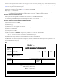
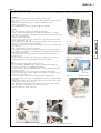
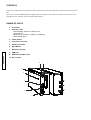
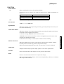
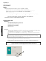
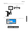
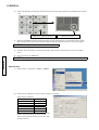
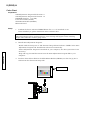
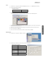
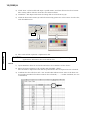
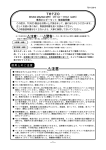
(2890)A 1
MINOLTA DiMAGE SCAN Elite 5400
(2890-100)
CODE
Scanner Type
35mm film scanner, moving film type
Usable Film Type
35mm film (Color / B&W, negative/positive)
Scanning Dimension
35mm film: 24.61 x 36.69 mm / 5,232 x 7,800pixels
Optical Resolution
5400dpi
Scanning method
Fixed sensor, moving film, single-pass scan
Image Sensor
3-line CCD with 5,300 pixels per line, RGB primary color filter
Scan Time (excluding the data transfer time to PC)
- Times listed above do not include data transfer time to the computer.
- Scan time varies with the film images and the scanner preferences and functions used.
- Scan time can be longer for negative film than positive film.
- Approximate time with 5400 dpi (maximum optical resolution), 8-bit color depth,
- No cropping, No auto exposure, No color matching, No Digital ICE processing, No image corrections, No
Grain Dissolver, No Multi-sample scanning
Setting
Mode
Index scan
Prescan
Scan
USB2.0
15 sec.
10 sec.
60 sec.
Scan time (Approx.)
Windows
IEEE1394
15 sec.
10 sec.
68 sec.
Macintosh
FireWire
16 sec.
12 sec.
69 sec.
Measuring condition
CPU
OS
RAM
Hard-disk space
Interface
Application
Memory allocated to
application
Windows
Pentium 4/ 2.53GHz
Windows XP Professional
1GB
60.9GB
USB2.0 built-in
IEEE 1394 Melco IFC-ILP4
Photoshop 7.0.1
80%
Macintosh
PowerPC G4
Mac OS X 10.2.1
1GB
70.72GB
FireWire built-in
Photoshop 7.0.1
739MB
CODE
2 (2889)A
AD Conversion
16bit (per color channel)
Output
8/ 16bit (per color channel)
Dynamic Range
3.8 (Tested value)
Light Source
3-wavelength cold-cathode fluorescent lamp
(Not user-replaceable)
Focus
Auto focus (Point AF available)
Manual focus (driver software/manual focus dial)
Others
Grain Dissolver, Auto Dust Brush, Digital ICE, Pixel Polish, Quick scan
button
Interface
IEEE1394 (FireWire)(One 6-pin receptacle connector)
USB 2.0 (Type-B connector), Compatible with USB1.1
Power Requirements
Scanner
AC Adapter
24V DC / 0.84A
Input: 100- 120 / 200 - 240V AC, 50/60Hz
Output: 24V DC / 0.84A
Power Consumption
Maximum 30W
Size
65mm (W) x 165mm (H) x 360mm (D)
Weight
Approx. 2.5kg
Standard Accessory
AC Adapter
35mm Film Holder FH-M10 <7890-240>
Slide Mount Holder SH-M10 <7890-241>
USB Cable UC-2 <7889-810>
IEEE1394 Cable FC-2 <7890-810>
Stand ST-M10 <7890-340>
Tool set RT-M10 <7890-341>
DiMAGE Scan <7310-002>
Photoshop Elements 2.0 <8700-532> (E/F/G/S/I)
Photoshop Elements 2.0 <8700-533> (Japanese)
AC-U22 <8700-715> (ME, MS)
200-240V AC, 50Hz for continental Europe, Oceania, and Asia
(except for Taiwan, Japan, Hong Kong, and China)
AC-U23 <8700-716> (ME/MGB, MK)
200-240V AC, 50Hz for England, Hong Kong, and China
AC-U24 <8700-717> (SMO)
200-240V AC, 50Hz for China.
AC-U25 <8700-718> (MC, MCI, MK, MSJ)
120V AC, 50/60Hz for North America, Taiwan, and Japan
Operating Environment
Temperature 10 to 35 degreesC, Humidity 15 - 85 %RH non-condensing
Storage Environment
Temperature -20 to 60 degreesC, Humidity 15 - 85 %RH non-condensing
(2890)A 3
System Requirements
IBM PC/AT compatible computers
OS
RAM(*1)
Pentium 166MHz or later processor
PowerPC G3 or later processor
USB: Mac OS 8.6 to 9.2.2, Mac OS X v10.1.3
USB: Windows98, 98 Second Edition, Me,
to v10.1.5, and v10.2.1 to 10.2.3
2000 Professional, or XP Professional
IEEE1394: Windows Me, 2000 Professional, FireWire: Mac OS 8.6 (*2)to 9.2.2, Mac OS X
v10.2.1 to 10.2.3
or XP Professional
128MB of RAM or more in addition to the
128MB of RAM or more
requirements for the Mac OS and
applications
Hard-disk
space(*1)
Monitor
Application
Interface
Application
600MB or more
1024x768 or greater is recommended.
A monitor with 640x480 pixels can be used.
A 16-bit or greater
32,000 colors or more
Adobe Photoshop 5.5, 6.0.1, 7.0,
The plug-in driver software has been tested
Adobe Photoshop Elements,
or use with Photoshop 5.5, 6.0.1, 7.0, and
P&A Paint Shop Pro 7.0,
Photoshop Elements.
Corel PHOTO-PAINT 10.0
USB port as standard interface,
Adaptec:
USB2connect 3100,
Standard USB port supplied by Apple
USB2connect 5100, DuoConnect.
Computer.
Belkin:
Hi-speed USB 2.0 5-Port PCI Card,
USB 2.0 Hi-Speed 2-Port PCI Card
The plug-in driver software has been tested
or use with Adobe Photoshop 6.0.1, 7.0.1,
The plug-in driver software has been tested
Adobe Photoshop Elements 2.0,
or use with Photoshop 6.0.1, 7.0.1, and
P&A Paint Shop Pro 7.0,
Photoshop Elements 2.0.
Corel PHOTO-PAINT 11.0
*1: See below for use of CPU, RAM, hard-disk space requirements with 16-bit color depth,
Pixel Polish :ON.
*2: FireWire 2.32 to 2.3.3 is necessary for use on Mac OS 8.6.
System Requirements with 16-bit color depth / Pixel Polish
Windows
CPU
RAM
Hard-disk space
16-bit color depth
Pentium II (Pentium 166MHz)
or later processor
256MB (128MB)
2GB (1.2GMB)
8-bit, Pixel Polish: ON
Pentium III (Pentium 166MHz)
or later processor
512MB (256MB)
2GB (1.2GB)
System Requirements with 16-bit color depth / Pixel Polish
Macintosh computers
CPU
RAM
Hard-disk space
16-bit color depth
8-bit, Pixel Polish: ON
PowerPC G4 (PowerPC G3) or later
PowerPC G4 (PowerPC G4) or later
processor
processor
256MB (128MB) of RAM in addition
to the requirements for the Mac OS and applications
2GB (1.2GMB)
To use the plug-in with Photoshop or Photoshop Elements on Mac OS 8.6 to 9.2.2, add the above
memory requirements to Photoshop’s suggested application memory allocation.
CODE
CPU(*1)
Macintosh computers
How to use a Parts List.
Product code and product name are shown on each page. You can close them by clicking the "[-]" on the left,if not necessary.
Parts list: Clicking [+] of bookmark displays the subordinate headings and clicking the number jumps to each page.
Blue for new parts No.by additional parts.
Red line for discontinued parts.
Illustration: Clicking the parts number "!/!" displays related PML.
Right page: * for amendments.
PML: Clicking the page number "*/*" displays related illustration page. Clicking [+] of bookmark displays the
subordinate headings and clicking number jumps to each page. (PML amendment advices)
About the written contents of a parts list.
Actual construction or shape of the parts may not be identical to the drawing in this Parts List.
Those parts are still applicable unless otherwise specified by a Parts Modification List.
The Parts Modification List will be issued if a modification causes incompatibility with original parts,
or results in greatly different parts from the original in shape or construction.
About the written contents of a PARTS MODIFICATION LIST.
Description for each item in PML.
(1) Code number of the model and page number.
(2) Reference No..
(3) Relevant page of Parts List.
(4) Reference No. of its creation post is shown.
(5) Number of relevant Supplementary Information if any.
(6) Reason of modification.
(7) Models in which the part is used in common.
(8) Previous parts number.
(9) New parts number.
(10) The part marked as " Previous " is no longer available as a service part. Use new Part.
(11) Arrow !", #$ show parts interchangeability.
! % !×$ : Previous part can be !cannot be$ replaced with new part.
× !%$ # : New part cannot be !can be$ replaced with previous part.
(12) Name of the newly added part. See Parts List for the name of current Parts.
(13) Description of the modification.
(14) When the part cannot be replaced as a single one, vertical colum shows the related parts to be replaced as a set.
Arrows !", #$ at base of table show interchangeability or parts as a set.
(15) Continued on the next page.
Ex.
(1234)A 1 (1)
(2)
"#No.
REF No.
QS FA 1234-P001
PARTS MODIFICATION LIST
Approved by
JK
$"%& "#$%&'
Divison
Camera CS Division
'()*+
Valid from August 1,2003
(3)
Parts List P.1
,-#.
REASON
Previous
(10)
(4)
Verified by
LM
Written by
NO
(5)
****-* SUPPLEMENTARY INFORMATION No. QS FA 1234-S01E
FGHI
COMMON
MODEL
(6)
(8)
BC(D) (C)DE
(11)
(7)
(9)
New
(12) Addeid./()
1234-5678-90 (Parts No.)
ABC ASSY (Part name)
ABC /01(%234)
(13)
New
(14) /0156789/ Interchangeability as a set. Previous BC(D) (C)DE
(15) Continued on the next page./:;<=>?@A
(2890)A 1
INDEX
PART NO.
PAGE
PART NO.
PAGE
2
2890-9001 ………………………
1
2890-0111 ………………………
1
2890-9002 ………………………
1
2890-0187 ………………………
1
2890-9003 ………………………
2
2890-0401 ………………………
2
2890-9004 ………………………
2
2890-0402 ………………………
2
2890-9005 ………………………
2
2890-0626
. . . . . . . . . . .
1
2890-0037
. . . . . . . . . . .
1
2890-9006 ………………………
2
2890-1002 ………………………
1
2890-9007 ………………………
2
2890-1003 ………………………
2
2890-9101 ………………………
2
2890-1004 ………………………
1
2890-9102 ………………………
2
2890-1005 ………………………
1
2890-1006 ………………………
1
9384-2191-00………………………
1,2
2890-1007 ………………………
1
9384-2191-01………………………
1
2890-1008 ………………………
1
9384-2792-00………………………
1,2
2890-1009 ………………………
1
2890-1102 ………………………
2
2890-1201 ………………………
1
2890-1301 ………………………
1
2890-1302 ………………………
1
2890-1303 ………………………
1
2890-0188 . . . . . . . . . . .
1
2890-4001 ………………………
2
2890-4002 ………………………
1
2890-4003 ………………………
1
2890-4004 ………………………
2
2890-4005 ………………………
2
2890-4006 ………………………
2
2890-4007 ………………………
1
2890-4101 ………………………
2
2890-4201 ………………………
2
2890-5851 ………………………
1
2890-0065
................
3
2890-0091
................
4
PARTS LIST
2890-0110 ………………………
2890-9001-01 (4)
PARTS LIST
2890-1002-01
2890-9001-01 (2)
2890-9001-01 (2)
2890-4007-01
2890-1008-01
2890-1004-01
9384-2191-01
(10x30mm)
2890-1007-01
2890-0626-01
2890-4003-01
2890-0187-01
2890-0188-01
See page 2.
9384-2191-00 (4)
(10x20mm)
9384-2792-00
(18x18mm)
2890-9002-01 (2)
(2890-1009-01)
2890-1201-01
2890-1006-01
2890-1302-01
2890-1303-01 (2)
2890-1005-01
2890-9001-01 (2)
2890-0037-01
2890-1301-01
(2890-4002-01)
2890-9002-01 (2)
2890-0111-01
2890-5851-01
2890-1303-01 (2)
2890-9001-01 (2)
2890-9001-01
5mm
2890-9002-01
7.5mm
8mm
M3
8mm
2.6mm
(2890)A 1
PART NO.
PART NAME
2890-0111-01
ASSY, FRONT HOUSING
QTY.
1
(2890-1009-01) POWER BUTTON
電源ボタン
1
(2890-4002-01) CABEL 6P
ケーブル6P
1
2890-0187-01
USB TERMINAL COVER
USBターミナルカバー
1
2890-1002-01
UPPER CASE
上ケース
1
2890-1004-01
PLATE SAFETY
定格ラベル
1
2890-1005-01
SERIAL NUMBER LABEL
ボディNO.ラベル
1
2890-1006-01
FOCUS DIAL
フォーカスダイアル
1
2890-1007-01
ARM
アーム
1
2890-1008-01
POWER SW. SP
電源SW SP
1
2890-1201-01
GEAR 12T
ギア12T
1
2890-1301-01
RUBBER HOLDER-A
ラバーホルダーA
1
2890-1302-01
RUBBER HOLDER-B
ラバーホルダーB
1
2890-1303-01
RUBBER STAND
ラバースタンド
4
2890-4003-01
FFC CABEL 18P
FFCケーブル18P
1
2890-4007-01
COIL
コイル
1
2890-5851-01
ICE STICKER
ICEシール
1
2890-9001-01
SCREW
ねじ
12
2890-9002-01
SCREW
ねじ
4
9384-2191-00
DOUBLE-FACED TAPE (PER ROLL)
両面テープ
4
9384-2191-01
DOUBLE-FACED TAPE (PER ROLL)
両面テープ
1
9384-2792-00
FILM TAPE-A (PER ROLL/BLACK)
フィルムテープA
1
2890-0626-01
SCREW
2890-0037-01
WASHER
2890-0188-01
IEEE CAP
PARTS LIST
前カバーセット
2890-4004-01
2890-0401-01
2890-9003-01 (2)
PARTS LIST
(2890-4101-01)
2890-4005-01
9384-2792-00
(8x20mm)
2890-0110-01
2890-9003-01 (2)
(2890-4006-01)
(9384-2191-00)
(10x10mm)
(9384-2191-00)
(10x20mm)
(2890-1102-01)
(2890-9007-01) (2)
Not available as a single part.
単品非供給
(2890-4201-01)
(2890-9102-01) (2)
(2890-4001-01)
2890-0091-01
2890-0065-01
(2890-9101-01) (2)
(2890-9006-01) (4)
2890-1003-01
2890-9005-01
5.5mm
2890-9005-01 (2)
8mm
2890-0402-01
M3
2890-9003-01
2890-9006-01
3.5mm
6mm
8mm
7mm
M3
2mm
2890-9004-01
2890-9007-01
3.2mm
5.8mm
5mm
10mm
2890-9004-01 (4)
3mm
M2
(2890)A 2
PART NO.
PART NAME
2890-0110-01
ASSY, SCAN UNIT
QTY.
1
(2890-1102-01) REFLECTION PLATE
反射板
1
(2890-4001-01) FLUORECSENT LIGHT
蛍光灯
1
(2890-4006-01) FFC CABEL 8P
FFCケーブル8P
1
(2890-4201-01) MOTOR
モーター
1
(2890-9006-01) SCREW
ねじ
4
(2890-9007-01) SCREW
ねじ
2
(2890-9101-01) PLATE WASHER
ワッシャ
2
(2890-9102-01) PLATE NUT
ナット
2
(9384-2191-00) DOUBLE-FACED TAPE (PER ROLL)
両面テープ
2
2890-0401-01
メイン基板セット
1
(2890-4101-01) MOTOR DRIVE IC
モーター駆動IC
1
2890-0402-01
IF16 PCB ASSY
IF16基板セット
1
2890-1003-01
LOWER CASE
下ケース
1
2890-4004-01
CABLE 4P
ケーブル4P
1
2890-4005-01
CABLE 30P
ケーブル30P
1
2890-9003-01
SCREW
ねじ
4
2890-9004-01
SCREW
ねじ
4
2890-9005-01
SCREW
ねじ
2
9384-2792-00
FILM TAPE-A (PER ROLL/BLACK)
フィルムテープA
1
2890-0065-01
GEAR 24
2890-0091-01
FOCUS MOTOR
MAIN PCB ASSY
PARTS LIST
撮像ユニット
(2890)A 1
REF No.
管理No.
PARTS MODIFICATION LIST
QS FA 2890-P001
DPCS Division
Division
DPCS部
主管部署
Valid from
March 17. 2003
施行年月日
Parts List P. 2
Approved by Verified by
Written by
承認
審査
作成
Tanizaki
Naruto
Ueno
Tozuka
仮-891
REASON サービス供給として設定する
変更理由 To supply as a spare part
2890-0110-01
Previous
Previous
――――――
COMMON
MODEL
共通機種
――
――
2890-100
2890-0110-01
(2890-4201-01)
――
――
New
New
(2890-4201-01)
MOTOR
モーター
A d d e d . / 新規手配
REF No.
管理No.
QS FA 2890-P002
DPCS Division
Division
DPCS部
主管部署
Valid from
March 17. 2003
施行年月日
Parts List P. 2
仮-891
REASON サービス供給として設定する
変更理由 To supply as a spare part
2890-0401-01
Previous
Previous
――――――
COMMON
MODEL
共通機種
――
――
――
――
2890-100
2890-0401-01
(2890-4101-01)
New
New
PML
(2890-4101-01)
MOTOR DRIVE IC
モーター駆動 I C
A d d e d . / 新規手配
■本案内状に従い、パーツリストへの転記等、メンテナンスを行なってください。
According to this list, correct “Parts List” in Service Manual for effective parts management.
KONICA MINOLTA CAMERA,INC.
(2890)A 2
REF No.
管理No.
PARTS MODIFICATION LIST
QS FA 2890-P003
CS Division
Division
CS部
主管部署
Valid from
April 27. 2004
施行年月日
Parts List P. 1
Approved by Verified by Written by
作成
Tanizaki
Naruto
Ueno
仮-897
――
――――――
審査
COMMON
MODEL
共通機種
REASON サービス供給として設定する
変更理由 To supply as a spare part
Previous
承認
――
2890-100
2890-0187-01
New
2890-0187-01
USB TERMINAL COVER
U S B ターミナルカバー
To suuply as a spare part.
サービス供給として設定
REF No.
管理No.
QS FA 2890-P004
CS Division
Division
CS部
主管部署
Valid from
April 27. 2004
施行年月日
Parts List P. 1
仮-897
COMMON
MODEL
共通機種
REASON サービス供給として設定する
変更理由 To supply as a spare part
PML
Previous
――――――
――
――
2890-100
2890-5851-01
2890-5851-01
ICE STICKER
I C E シール
To suuply as a spare part.
サービス供給として設定
■本案内状に従い、パーツリストへの転記等、メンテナンスを行なってください。
According to this list, correct “Parts List” in Service Manual for effective parts management.
KONICA MINOLTA PHOTO IMAGING, INC.
New
(2890)A 3
REF No.
管理No.
PARTS MODIFICATION LIST
QS FA 2890-P005
Camera CS Division
Division
カメラCS部
主管部署
Valid from
October 15. 2004
施行年月日
Parts List P. 1
Approved by Verified by Written by
作成
Tanizaki
Naruto
Ueno
仮-911
――
――――――
審査
COMMON
MODEL
共通機種
REASON サービス供給として設定する
変更理由 To supply as a spare part
Previous
承認
――
2890-100
2890-0626-01
New
2890-0626-01
S C R E W / ねじ
A d d . / 新説
REF No.
管理No.
QS FA 2890-P006
Camera CS Division
Division
カメラCS部
主管部署
Valid from
October 15. 2004
施行年月日
Parts List P. 1
仮-911
COMMON
MODEL
共通機種
REASON サービス供給として設定する
変更理由 To supply as a spare part
Previous
――――――
――
――
2890-100
2890-0037-01
New
PML
2890-0037-01
W A S H E R / ワッシャ
A d d . / 新説
■本案内状に従い、パーツリストへの転記等、メンテナンスを行なってください。
According to this list, correct “Parts List” in Service Manual for effective parts management.
KONICA MINOLTA PHOTO IMAGING, INC.
(2890)A 4
REF No.
管理No.
PARTS MODIFICATION LIST
QS FA 2890-P007
Camera CS Division
Division
カメラCS部
主管部署
Valid from
October 15. 2004
施行年月日
Parts List P. 1
Approved by Verified by Written by
――――――
審査
作成
Tanizaki
Naruto
Ueno
仮-911
COMMON
MODEL
共通機種
REASON サービス供給として設定する
変更理由 To supply as a spare part
Previous
承認
――
――
2890-100
2890-0188-01
PML
2890-0188-01
IEEE CAP
I E E E キャップ
A d d . / 新説
■本案内状に従い、パーツリストへの転記等、メンテナンスを行なってください。
According to this list, correct “Parts List” in Service Manual for effective parts management.
KONICA MINOLTA PHOTO IMAGING, INC.
New
(2890)
REF No.
管理No.
5
PARTS MODIFICATION LIST
QS FA 2890-P008
Camera CS Division
Division
カメラCS部
主管部署
Valid from
July 15. 2005
施行年月日
Parts List P. 2
Approved by Verified by Written by
承認
Yata
――――――
――――――
作成
Ueno
仮-939
COMMON
MODEL
共通機種
REASON サービス供給として設定する
変更理由 To supply as a spare part
Previous
Previous
審査
――
――
――
――
2890-100
2890-0065-01
2890-0091-01
New
New
2890-0091-01
FOCUS MOTOR
フォーカスモータ
N E W / 新規設定
2890-0065-01
GEAR 24
ギヤ 2 4
N E W / 新規設定
PML
■本案内状に従い、パーツリストへの転記等、メンテナンスを行なってください。
According to this list, correct “Parts List” in Service Manual for effective parts management.
KONICA MINOLTA PHOTO IMAGING, INC.
(2890) A 1
REPAIR GUIDE
Contents of this manual are in accordance with the assembly procedure.
Therefore, follow the reverse procedure when disassembling.
SYMBOLS
: Caution and key points of assembly
: Anti-diffusion agent
: Adhesive
: Grease
: Tools
TABLE OF CONTENTS
Page
PRECAUTIONS
Chemicals
Handle chemicals of high volatility with care, use of which will affect to your health and environment.
1. Store them sealed in a specific place to prevent from exposure to high temperature or direct sunlight.
2. Avoid dividing them into small containers and prevent from vaporization.
3. Keep containers sealed when not in use.
4. Avoid using them as much as possible. When required, remove only required amount from the container
to make full use.
Plastic Parts
1. When cleaning the plastic parts, use cleaning paper or cloth. Never apply thinner, ketone, ether.
2. When installing the plastic parts, insert the specific screws vertically to the parts. (Be careful not to
tighten too much.)
PCBs
Since PCBs use MOS IC, you must reduce static electricity.
When repair a PCB itself, or when wiring, please perform your work as illustrated below.
If grounding is impossible, connect a cable to a steel desk or shelf.
Keep touching the conductive mat while you work.
1M!
Conductive Mat
GND
2
3
8
8
REPAIR GUIDE
Assy, Scan unit, Main PCB Assy Installation .....................................................................................................
Focus dial, Arm, Assy, Front housing Installation .............................................................................................
Measuring Instruments, Tools and Jigs ..............................................................................................................
Subsidiary Materials ............................................................................................................................................
2
Assy, Scan unit, Main PCB Assy Installation
Fig. 4
Cable 4P
Main PCB Assy
9003 (2)
B-10
Fig. 3
B-51
REPAIR GUIDE
Cable 30P
9384-2792-00
(8x20mm)
Fig. 2
Assy, Scan unit
9003(2)
FFC Cable 8P
9384-2191-00
(10x10mm)
9384-2191-00
(10x20mm)
Fig. 2
Reflection plate
9007 (2)
Not available as a single part.
Fig. 1
Nut (2)
Fluorecsent light
Washer (2)
9006(4)
Lower case
2890-9005-01
5.5mm
9005 (2)
8mm
IF 16 PCB assy
M3
2890-9003-01
2890-9006-01
3.5mm
6mm
8mm
7mm
M3
2mm
2890-9004-01
2890-9007-01
3.2mm
5.8mm
5mm
10mm
9004 (4)
3mm
M2
3
Focus dial, Arm, Assy, Front housing Installation
9001 (4)
Upper case
REPAIR GUIDE
9001 (2)
9001(2)
Coil
Power SW SP
Fig. 5
Fig. 6
Plate safety
9384-2191-01
(10x30mm)
Arm
Fig. 8
FFC cable 18P
Fig. 2
9384-2792-00
(18x18mm)
9384-2191-00 (4)
(10x20mm)
Fig. 2
9002 (2)
Power button
Fig. 9
Gear 12T
Rubber holder-B
Rubber stand (2)
Serial number label
9001 (2)
Rubber holder-A
Cable 6P
Assy, Front housing
Rubber stand (2)
9002 (2)
9001 (2)
Fig. 9
Focus dial
2890-9001-01
5mm
2890-9002-01
7.5mm
8mm
M3
8mm
2.6mm
4 (2890) A
REPAIR GUIDE
" Fig. 1
Fluorescent Lamp Replacement Procedure.
Disassembly
1. Remove 4 fluorescent lamp holder (not supplied) fixing
screws (9006) (in the circle). Never loosening fluorescent
lamp holder fixing screws except the screws marked in the
figure (in the circle).
Assembly
1. Install nut (9102) to the fluorescent lamp holder (not
supplied) and fluorescent lamp (4001) in a groove of the
nut.
2. Remove 2 fluorescent lamp fixing screws (9007). Remove
washers (9101), a reflection board (1102) and a fluorescent
lamp.
2. Install reflection boards (1102), washers (9101) and
harness terminal, and install 2 screws (9007).
3. Install the fluorescent lamp holders (not supplied) and fix with
4 screws (9006). (See Disassembly step 1)
4. Arrange the harness.
Notice:
When fixing fluorescent lamp terminal with screws,
stress is applied, and a leak of fluorescence gas
rarely occurs.
Be sure to leave the fluorescent lamp more than
24 hours (1day), and please ship repair product
after lighting confirmation of the fluorescent lamp.
(2890) A 5
" Fig. 2
FFC cable 18P
20mm
Bend at this line.
FFC cable 8P
Bend at this line
9384-2191-00(10x10mm)
35mm
9384-2191-00(10x20mm)
Put through downside.
Put through a hole of Main PCB.
REPAIR GUIDE
FFC cable 18P
FFC cable 18P
9384-2191-00(10x20mm)(3)
Attach FFC cable 18P
to Image taking unit.
FFC cable 8P
9384-2191-00(10x20mm)
Attach FFC cable 8P
to Image taking unit.
FFC cable 8P
FFC cable 18P
9384-2792-00(18x18mm)
9384-2792-00(8x20mm)
" Fig. 3
After connectig Main PCB Assy and Cable 30P, apply B-51 and B-10 to the connector of PCB as shown.
B-10
Ferrite core
B-51 Apply B-51to the connected part of Cable 30P and PCB,
Ferrite core and PCB, and leave them for hardening.
6 (2890) B
" Fig. 4
" Fig. 5
Connect the connector by the position as shown.
The red / brown solenoid
Red / black inverter PCB
Coil installation.
Coil
Main PCB
REPAIR GUIDE
Red / orange Power SW
Bottom cover
" Fig. 6
Arm installation.
Install the arm notch aligning with the Image taking unit.
(in the circle)
9384-2191-01(10x30mm)
Install a coil into the bottom cover.
After installing the coil on the lower case with 9384-2191-01,
apply B-51 into the shaded area to prevent the coil from
detaching.
Coil
Arm
Power SW SP
B-51
" Fig. 7
Serial number installation.
" Fig. 8
Rating label installation.
Stick a rating label as shown in the figure after fixing
top cover with screws.
Stick onto the center of the posts.
Do not let it run over the top cover.
(2890) A 7
" Fig. 9
Focus dial Assembly Procedure.
DiMAGE Scan Utility is necessary for this procedure. Please install "DiMAGE Scan" Software from CD-ROM to your PC.
Preparations
1. Remove top cover, front cover assy, focus dial and gear 12T.
2. Keep the front cover assy connected to the Image taking unit with cable 6P.
(Fig. 9-1)
3. Connect scanner (2890) and PC via USB (or, IEEE1394) cable.
4. Power on the scanner.
5. Start "DiMAGE Scan Utility", and be standby for scanning.
Check
Check the position and operation of the Focus dial.
Connect an USB (or, IEEE1394) cable same as normal image bringing in,
power on the scanner to start "DiMAGE Scan Utility".
1. Set an image in a holder (35mm film holder or a slide mount holder), and
insert it in a scanner.
The holder stops at a center position after moving in right and left.
2. Confirm that the index (a dent) of Focus dial is within a illustrated range.
(between arrows) (Fig. 9-5)
If it was out of the range, repeat from Assembly procedure step 1.
3. Preview the image set in step 1 on DiMAGE Scan Utility, and perform AF at
any point.
Check that the holder moves in left and right, moves again in short range,
and then stops at the best focus point.
4. Push Eject button. Confirm that Focus dial returns to the initial position
after ejecting. (the end position in clockwise direction)
5. Arrange cable 6P as shown. (Fig. 9-6)
Fig. 9-6
Fig. 9-5
Index
Arrange at the notch.
Cable 6P
Fig. 9-2
Tape
Fig. 9-3
Projection
REPAIR GUIDE
Assembly
1. Keep the front door being opened with tape. (Fig. 9-2)
2. Insert a holder (35mm film holder or a slide mount holder) in a scanner.
(it's arbitrary to set film or not) Holder moves in right and left direction, and
stops at a central position.
3. Install gear 12T to Focus dial.
Align a groove of gear 12T. (two places) with a projection of the focus dial
inside, and install it. (Fig. 9-3)
4. Make an index (a dent) of a focus dial (a set with gear 12T) just above, and
install it to a gear shaft. (Image taking unit).
5. Mark on the engaged part of gear teeth adjacent to the gear 12T with a felt
pen. (Fig. 9-4)
6. Push an Eject button, and pull out a holder.
After ejecting, Focus dial turns clockwise, and stops at the initial position.
7. Turn Focus dial manually in counterclockwise direction so that the index (a
dent) appears just above.
Check that position of the gear 12T and adjacent gear tooth (marked
position) are fit.
8. Be sure to peel off the tape which was put in Assembly step 1 (Fig. 9-2).
9. Install the front cover assy and tighten with 4 screws (9002).
Fig. 9-1
Focus dial
Fig. 9-4
Cable 6P
Arrange under the PCB.
Groove
Gear 12T
Marked position
Index (a dent)
8 (2890) A
Measuring Instruments, Tools and Jigs
REPAIR GUIDE
Slide Mount Holder (SH-M10)
DiMAGE Scan Ver. 1.1.0 (CD-ROM)
AC Adapter
PC/AT compatibles
CPU: Pentium III or later
RAM: 500MB or more
HDD: Approx. 2GB or more of available hard-disk space
OS: Windows 98, 98SE, Me, 2000 Professional
Monitor: 1024 x 768 (pixels) is recommended. High Color (16-bit)
Subsidiary Materials
Adhesive
B-10 <7984-2010-01>
B-51 <7984-2051-01>
(2890) A 1
CHECK LIST
1. This Check List describes the quality of operation warranted to general users.
When users inquire about quality or request inspection, refer to this Check List.
Use this list also when checking operation after repair.
2. When using this list at shipping or receiving inspection, judge the quality according to the purpose of the
inspection, not by directly referring to this level.
3. For individual taste or special usage, some users may not be satisfied with this level of quality and will
request a different one.
In such cases, adjust the level as required by them as much as possible.
Contents
NAMES OF PARTS
PARTS................................
................................................................
................................................................................................
................................................................................................
.................................................................................
................................................. 2
FUNCTION................................
FUNCTION................................................................
................................................................................................
................................................................................................
..............................................................................................
.............................................................. 3
PERFORMANCE ................................................................
................................................................................................
................................................................................................
....................................................................................
.................................................... 4
SCANNER GAUGE CHART ................................................................
................................................................................................
................................................................................................
..................................................................
.................................. 4
COLOR CHART
CHART................................
................................................................
................................................................................................
................................................................................................
.......................................................................................
....................................................... 8
STANDARD ................................................................
................................................................................................
................................................................................................
...........................................................................................
........................................................... 11
EQUIPMENT REQUIRED
REQUIRED................................
................................................................
................................................................................................
................................................................................................
...................................................................
................................... 12
CHECK LIST
POWER SWITCH ...........................................................................................................................................................3
PC INTERFACE ............................................................................................................................................................3
EJECT BUTTON ............................................................................................................................................................3
QUICK SCAN BUTTON ..................................................................................................................................................3
MANUAL FOCUS DIAL ..................................................................................................................................................3
INDEX SCAN .................................................................................................................................................................3
PRESCAN ......................................................................................................................................................................3
SCAN ............................................................................................................................................................................3
2 (2890) A
Check the scanner with the computer which meets the system requirements in the last page of this check
list.
The driver software DiMAGE Scan supplied with the product is necessary for check. If this driver is not
installed in the computer, please install it beforehand.
NAMES OF PARTS
1. Front Door
2. Indicator Lamp
Glows steadily: Scanner is ready to use.
Off: Power off
Blinks slowly: Scanning, Loading, or initializing.
Blinks rapidly: Error
3. Power Switch
4. Front Door reset hole
5. Quick Scan button
6. Eject Button
7. Manual Focus Dial
8. USB Port
CHECK LIST
9. IEEE1394 (FireWire) Port
10. DC Terminal
2
1
3
4
5
8
9
10
6
7
(2890) A 3
FUNCTION
Power Switch
ON
Before starting the driver, the indicator blinks.
At using the driver software, the indicator lamp glows or blinks accordingly as
below.
OFF
Lamp
Condition
Glowing
Normal except for the following.
Blinking slowly at 1Hz
Mechanical drive (setup)
Blinking fast at 8Hz
Error
The indicator lamp turns off.
PC Interface
USB 2.0 / 1.1 or IEEE1394
Eject button
When the scanner is not operating (stand-by), pressing the Eject button ejects
the holder immediately.
Quick Scan button
When the scanner is not operating (stand-by), pressing the Quick scan button
launched desired application software.
In default setting, DiMAGE Scan Launcher starts.
DiMAGE Scan Launcher enables to select the application which starts when
pressing the Quick Scan button.
Manual focus dial
When the Manual focus dial is selected in the preferences window, manual
focusing can be used on any point in the preview image.
While selecting the Manual focus dial, the Autofocus at scan is disabled.
Index Scan
Displays index in high speed or high quality as set in the preferences.
Prescan
Scans selected frames and displays on the prescan tab window.
Scan
Scans a selected frame and saves or export the image.
When selecting multiple images, scans them sequentially. (slide: max.4 frames/
film strip: max.6 frames)
CHECK LIST
If the batch scan utility is selected, the scanner starts scanning.
4 (2890) A
PERFORMANCE
Outline
Basically, 2890 performance will be checked accordingly as below.
Scan: Scan the chart and save the image with the driver software.
Measure: Take in the image and measure the data with the Adjustment program.
Check: Output the data in the excel sheet and check the performance.
Chart and check items:
Scanner gauge chart: magnification, skew, color registration, pitch accuracy, frequency
characteristic
Color chart: output density, grayscales, color balance, color reproduction
The following procedure describes the method in detail.
Scanner Gauge Chart
CHECK LIST
Preparation
2890 Adjustment Program FD Version 1.0
2887 Adjustment Program CD Version 1.0
DiMAGE Scan Ver. 1.1.0 (CD)
Scanner Gauge Chart (35mm)
Slide Mount Holder (SH-M10)
Microsoft Excel
Installation
1. Drag and copy “DiMAGEScan.ini” in the 2890 Adjustment Program FD to the folder where
the DiMAGE Scan.exe is installed. (C: Program Files \DiMAGE Scan)
If the driver software DiMAGE Scan is not installed yet, please install the driver software
first.
Be sure to remove the DiMAGEScan.ini from the folder after scanning the chart.
Otherwise images will be underexposed or error message will appear when scanning
images other than the scanner gauge chart.
2. Double click the Setup.exe at “CD:Scanner Gauge Chart Evaluate \DISK1 in the 2887
Adjustment Program CD. Installation will start automatically.
If 2887 Adjustment Program is launched on your computer, the above procedure is not
necessary.
CAUTION: The dialog box below may appear under the English environment OS, but the
program completes the installation successfully and will restart the PC
appropriately. Click the following point “A”.
!
(2890) A 5
Setting the chart
Make sure the chart faces the CCD side in the Slide Mount Holder (SH-M10) as illustrated.
Up: Fluorescent
Front view
Side view
Down: CCD
1) Click Start > Programs > Minolta DiMAGE Scan Ver. 1.1 > DiMAGE Scan Utility.
2) Set the preferences as below.
Scanning condition
Film format
Film type
Input resolution
35mm
Color Positive
5400 dpi
CHECK LIST
Scan
6 (2890) A
3) Select the blank area (A) and click the Prescan button and confirm if each RGB value is 200
"30.
A
RGB value should be 200!30
B
Manual focus Point
4) Click on the Manual focus button and move the mouse pointer to the manual focus point
(B), then drag the focus meter slider until the black and white lines are at their longest.
CAUTION: Drag the slider from the left to the right.
5) Confirm that the image is selected entirely, and click the Scan button to start the final
scan.
6) Save the image as .BMP file.
CHECK LIST
CAUTION: Chart scanning time is depending on the system configurations of the computer.
Measurement
1) Select Start > Program > DPEV > GEOM.
2) Click Setup > Measure and set the preference as below.
Measuring condition
Size
Auto Detect
Resolution
5400 dpi
Chart Size
135
MTF
20/30/40
Measure item
Check all
Data Out
Auto Save
Pasted MTF-Data
40
Click the Profile “New” and input a profile
name, and then click the Save button.
(The setting will be effective from the next
measurement.)
(2890) A 7
3) Click File > File Open and select the image file
saved in 1.3.7). The result will be copied in a clipboard on PC.
CAUTION: Paste the result data on an excel sheet in the next step before using other
applications.
Otherwise the result will be lost.
Check
1) Open 2890data sheet.xls in the FD and select the worksheet “Scanner Gauge”.
2) Move the mouse pointer to the cell F3, and click Edit > Paste.
The file name is inputted in F3 and the performance data is inputted in the column F.
3) Confirm that the cell G3 is null. * mark in G3 indicates that some of the data was beyond
the standard. Check the items marked * in the column G. (blank: within standard, *: out
of standard)
Be sure to remove the DiMAGEScan.ini from the folder after scanning the chart.
Otherwise images will be underexposed or error message will appear when scanning images
other than the scanner gauge chart.
CHECK LIST
8 (2890) A
Color Chart
Preparation
2890Adjustment Program FD Version 1.0
2887Adjustment Program CD Version 1.0
DiMAGE Scan Ver. 1.1.0 (CD)
Color Chart Slide (35mm)
Slide Mount Holder (SH-M10)
Microsoft Excel
Setup
1. Confirm the driver software DiMAGE Scan Ver. 1.1.0 is launched or not.
If not installed yet, please install the driver software first.
Be sure to remove the DiMAGEScan.ini from the folder after scanning the chart.
Otherwise images will be underexposed or error message will appear when scanning
images other than the scanner gauge chart.
2. Install 2887 Adjustment Program.
Double click the Setup.exe at “CD: Scanner Gauge Chart Evaluate \DISK1 in the 2887
Adjustment Program CD. Installation will start automatically.
CHECK LIST
If 2887 Adjustment Program is launched on your computer, the above procedure is not
necessary.
Drag and copy the 90Color135.txt from the 2890 Adjustment Program FD to your
computer.
3. Load the Color Chart Slide in the Slide Mount Holder (SH-M10) so that the jig No. is
visible from the fluorescent lamp side.
7982#5005-01
Jig NO.
(2890) A 9
Scan
1) Click Start > Programs > Minolta DiMAGE Scan Ver. 1.1 > DiMAGE Scan Utility.
2) Set the preferences as below.
Scanning condition
Film format
35mm
Film Type
Color Positive
Input resolution
540 dpi
3) Click on the Prescan button to prescan the chart.
Check that the chart is scanned as shown and that it is not underexposure.
4) Click on the Point AF button and move the mouse pointer to the center of the image
and then start the Auto Focus.
6) Save the image as .BMP file.
7) Add “_P0” after the file name as suffix (***(file name)_P0.BMP).
Measurement
1) Click Start > Program > DPEV > ColorEV.
2) Click Setup > Measure, and set the preference as below.
Measurement condition
Category
Resolution
Chart
Ver
Standard
Data Out
Locate
Sample Area
Gamma
Light Source
Scanner
540 dpi
135
6
90Color135.txt
Auto Save
File Group
Vert:0 Hriz:0 Scale: 1
1.5
1.4
D65 (Std)
CHECK LIST
5) Make sure that all the area of the image is selected and click on the Scan button.
10 (2890) A
3) Click “New” of the Profile and input a profile name, and then click on the Save button.
The setting will be effective from the next measurement.
4) Click File > File Open and select the image file saved in Scan step 6).
5) Click the direction buttons (A) until the measuring points are at the center of each color,
and click OK button.
A
CHECK LIST
6) The result will be copied in a clipboard on PC.
CAUTION: Paste the result data on an excel sheet in the next step before using other
applications. Otherwise the result will be lost.
Check
1) Open 2890data sheet.xls in the FD and select the worksheet “Color Chart”.
2) Move the mouse pointer to the cell F3, and click Edit > Paste.
The file name is inputted in F3 and the performance data is inputted in the column F.
3) Confirm that the cell G3 is null. “xxx” mark in G3 indicates that some of the data was
beyond the standard. Check the items in the column G ($
$ $: within standard, xxx: out
of standard)
(2890) A 11
Standard
Scanner gauge chart
Magnification
Vertical
Horizontal
Aspect ratio
+/± 1.5%
± 1.5%
± 1.0%
Vertical
Horizontal
Aspect ratio
+/± 0.5%
± 0.5%
± 0.5%
Skew
Color Registration
Vertical
Horizontal
+/± 1.5 pixel
± 1.5 pixel
Vertical
Horizontal
+/± 1.0 %
± 1.0 %
Pitch Accuracy
Center
Around
Vertical
Horizontal
Vertical
Horizontal
Range
50 % (40 lines/mm) or greater
50 % (40 lines/mm) or greater
40 % (40 lines/mm) or greater
40 % (40 lines/mm) or greater
Color chart
Output Density
Chart
White
Black
Range
94 ± 5
14 ± 8
Grayscales
Chart
Range
Step 1
White
100
Step 2
Gray2
94± 6
Step 3
Gray3
89 ± 5
Step 4
Gray4
77 ± 5
Step 5
Gray5
61 ± 5
Step 6
Black
17 ± 5
Confirm that L* value is less than 100, and all the values are in descending
order toward Black as shown above.
CHECK LIST
Frequency Characteristic
12 (2890) A
Color Balance
Chart
Step 1
Step 2
Step 3
Step 4
Step 5
Step 6
White
Gray2
Gray3
Gray4
Gray5
Black
Chart
B
G
R
Y
M
C
a*
23"10
-44"10
48"10
-5"10
50"10
-18"10
+/10 or less
10 or less
10 or less
10 or less
10 or less
16 or less
Color Reproduction
b*
-53 ± 10
13 ± 10
46 ± 10
51 ± 10
-19 ± 10
-32 ± 10
Equipment Required
CHECK LIST
PC/AT compatibles
CPU
Pentium III or later
RAM
500MB or more
HDD
Approx. 2GB or more of available hard-disk space
OS
Windows 98, 98SE, Me, 2000 Professional
Monitor
1024 x 768 (pixels) is recommended. High Color (16-bit)
2890Adjustment Program FD Version 1.0 <2890-0001-75>
FD
DiMAGEScan.ini
90Color135.dll
2890_data sheet.xls
2887Adjustment Program CD Version 1.0 <2887-0001-75>
Scanner Gauge Chart (35mm) <7982-5002-01>
Color Chart Slide (35mm) <7982-5005-01>
Slide Mount Holder (SH-M10)
Microsoft Excel
DiMAGE Scan Ver. 1.1.0 (CD-ROM)
AC Adapter