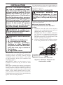
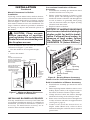
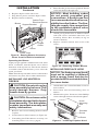
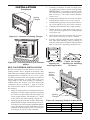
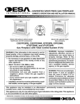
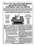
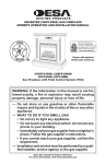
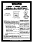
1
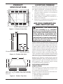
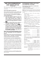
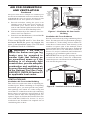
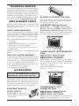
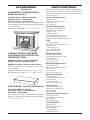
UNVENTED (VENT-FREE) UNIVERSAL FIREBOX
SAFETY INFORMATION AND INSTALLATION MANUAL
Shown with optional
cabinet mantel, hearth
base.
CGFB32CA
CIRCULATING LOUVERED MODEL
WARNING: If the information in this manual is not followed exactly, a fire or explosion may result causing
property damage, personal injury or loss of life.
Carefully review the instructions supplied with the
decorative type unvented room heater for the minimum
fireplace size requirement.
Do not install an appliance in this firebox unless this
firebox meets the minimum dimensions required for
the installation.
This firebox has been tested and approved by CSA
under ANSI Z21.91 for use with any ANSI Z21.11.2 approved gas logs.
This appliance may be installed in an aftermarket*, permanently located, manufactured (mobile) home, where
not prohibited by local codes.
This appliance is only for use with the type of gas indicated on the rating plate. This appliance is not convertible for use with other gases.
*Aftermarket: Completion of sale, not for purpose of resale, from the manufacturer
Save this manual for future reference.
For more information, visit www.desatech.com
WARNING: Improper installation, adjustment, alteration, service or maintenance can cause injury or property damage.
Refer to this manual for correct installation and operational
procedures. For assistance or additional information consult
a qualified installer, service agency or the gas supplier.
WARNING: For use only with a listed gas-fired unvented
decorative room heater. Not to exceed 40,000 Btu/Hr. Do not
build a wood fire.
State of Massachusetts: The installation must be made by a licensed plumber or gas fitter in the
Commonwealth of Massachusetts.
Sellers of unvented propane or natural gas-fired supplemental room heaters shall provide to each
purchaser a copy of 527 CMR 30 upon sale of the unit.
Vent-free gas products are prohibited for bedroom and bathroom installation in the Commonwealth of Massachusetts.
TABLE OF CONTENTS
Safety Information ............................................... 2
Local Codes ........................................................ 3
Unpacking ........................................................... 3
Product Features ................................................. 3
Product Specifications ......................................... 4
Locating Firebox ................................................. 4
Air For Combustion and Ventilation ..................... 4
Installation ........................................................... 7
Technical Service .............................................. 12
Replacement Parts ............................................ 12
Accessories ....................................................... 12
Parts Centrals .................................................... 13
Illustrated Parts Breakdown and Parts List ....... 14
Warranty Information ...........................Back Cover
SAFETY INFORMATION
IMPORTANT: Read this owner’s
manual carefully and completely
before trying to assemble, operate
or service this firebox. Improper
use of this firebox can cause serious injury or death from burns,
fire, explosion, electrical shock or
carbon monoxide poisoning.
WARNING: Any change to
this firebox or its controls can
be dangerous.
WARNING: Do not allow fans
to blow directly into the firebox.
Avoid any drafts that alter burner
flame patterns. Ceiling fans can
create drafts that alter burner
flame patterns. Altered burner
patterns can cause sooting.
2
WARNING: Do not use a blower insert, hood, heat exchanger
insert or other accessory not approved for use with this heater.
Due to high temperatures, the
firebox should be located out of
traffic and away from furniture
and draperies.
Firebox front and screen become very hot when running
firebox. Keep children and
adults away from hot surfaces to
avoid burns or clothing ignition.
Firebox will remain hot for a time
after shutdown. Allow surfaces
to cool before touching.
www.desatech.com
107331-01H
SAFETY INFORMATION
Continued
Do not place clothing or other
flammable material on or near
firebox. Never place any objects
on the firebox or logs.
Carefully supervise young children when they are in the room
with firebox.
You must operate this fireplace
with the provided fireplace screen
(closed), hood and brick liner in
place. Make sure these parts are
in place before running firebox.
Keep the firebox area clear and
free from combustible materials,
gasoline and other flammable
vapors and liquids.
1. This firebox shall not be installed in a bedroom
or bathroom.
2. Never install the firebox
• in a recreational vehicle
• where curtains, furniture, clothing or other
flammable objects are less than 42 inches
from the front, top or sides of the firebox
• in high traffic areas
• in windy or drafty areas
3. Do not use this firebox as a wood-burning
fireplace. Use only decorative unvented room
heaters (log sets).
4. Do not add extra logs or ornaments such as pine
cones, vermiculite or rock wool. Using these
added items can cause sooting.
5. Vent-free gas log heaters installed in these fireboxes require fresh air ventilation to run properly.
See Air for Combustion and Ventilation, page 4.
6. Do not run firebox
• where flammable liquids or vapors are used
or stored
• under dusty conditions
7. Do not use this firebox to cook food or burn paper
or other objects.
8. Turn firebox off and let cool before servicing.
Only a qualified service person should service
and repair firebox.
9. Operating vent-free log sets in a firebox above
elevations of 4,500 feet could cause pilot outage.
107331-01H
10. Do not use the firebox if it has been under water
due to the shock hazard that could result with
the blower accessary (if installed) in place.
11. Provide adequate clearances around air
openings.
LOCAL CODES
Install and use fireplace with care. Follow all local
codes. In the absence of local codes, use the latest edition of The National Fuel Gas Code ANSI Z223.1/
NFPA 54*. Firebox must be electrically grounded
in accordance with the National Electrical Code,
ANSI/NFPA70 (latest edition).
*Available from:
American National Standards Institute, Inc.
1430 Broadway
New York, NY 10018
National Fire Protection Association, Inc.
Batterymarch Park
Quincy, MA 02269
UNPACKING
1. With utility knife, cut the carton all the way
around above the staples on the bottom tray. Lift
the carton off the firebox. Remove packing.
2. Check carton contents for the following:
• Screen assembly
• Screen support rod
• Hardware and parts bag containing the following:
- Ownerʼs Operation and Installation Manual
- 2 - Black #10 x 3/8" Phillips screws
3. If any items are missing, inform dealer where
you bought the firebox.
4. Check all items for any shipping damage. If
damaged, promptly inform dealer where you
bought firebox.
PRODUCT FEATURES
OPERATION
This firebox is designed to accept unvented
decorative gas logs. It requires no outside venting or chimney making installation easy and
inexpensive. When used without the blower the
firebox requires no electricity making it ideal for
emergency backup heat.
BLOWER ACCESSORY
The CGFB32CA firebox will accept the GA3750A
accessory. The variable blower allows you to select
the fan speed you desire. The blower circulates
heated air from the firebox into the room. Use of
blower is optional.
www.desatech.com
3
PRODUCT
SPECIFICATIONS
LOCATING FIREBOX
35 1/16"
3 7/8"
2 3/4"
1 1/4"
1 1/4"
19 3/8"
16 1/4"
31 3/4"
2 3/4"
6 3/4"
6 3/8"
Built-in Nailing Flanges
Figure 1 - Firebox Front View
2 1/4"
6"
33 11/16"
32 3/16"
12 1/2"
9 3/4"
4 5/8"
2 1/2"
Electrical Access Hole
Gas Line Access
Figure 2 - Firebox Side View
22 1/2"
13 1/4"*
14 1/4"
16 11/16"
19 1/4"
Plan where you will install the firebox. This will
save time and money later when you install the firebox. Before installation, consider the following:
1. Where the firebox will be located. Allow for
wall and ceiling clearances (see Installation
Clearances, page 7).
2. Everything needed to complete installation.
3. These models CANNOT be installed in a
bedroom or bathroom.
4. Proper air for combustion and ventilation (see
Air For Combustion and Ventilation).
AIR FOR COMBUSTION
AND VENTILATION
WARNING: This firebox shall
not be installed in a confined
space or unusually tight construction unless provisions are provided for adequate combustion and
ventilation air. Read the following
instructions to insure proper fresh
air for this and other fuel-burning
appliances in your home.
Todayʼs homes are built more energy efficient
than ever. New materials, increased insulation and
new construction methods help reduce heat loss
in homes. Home owners weather strip and caulk
around windows and doors to keep the cold air out
and the warm air in. During heating months, home
owners want their homes as airtight as possible.
While it is good to make your home energy efficient, your home needs to breathe. Fresh air must
enter your home. All fuel-burning appliances need
fresh air for proper combustion and ventilation.
Exhaust fans, fireboxes, clothes dryers and fuel
burning appliances draw air from the house to
operate. You must provide adequate fresh air for
these appliances. This will insure proper venting
of vented fuel-burning appliances.
PROVIDING ADEQUATE
VENTILATION
31 5/8"
34 3/8"
35 5/8"
*Note: 141/4" is total firebox cavity depth including
brick liner. 131/4" is depth of flat floor including
brick liner.
Figure 3 - Firebox Top View
4
The following are excerpts from National Fuel
Gas Code ANSI Z223.1/NFPA 54, Section 5.3, Air
for Combustion and Ventilation.
All spaces in homes fall into one of the three following ventilation classifications:
1. Unusually Tight Construction
2. Unconfined Space
3. Confined Space
www.desatech.com
107331-01H
AIR FOR COMBUSTION
AND VENTILATION
Continued
The information on pages 4 through 6 will help
you classify your space and provide adequate
ventilation.
Unusually Tight Construction
The air that leaks around doors and windows may
provide enough fresh air for combustion and ventilation. However, in buildings of unusually tight construction, you must provide additional fresh air.
Unusually tight construction is defined as
construction where:
a. walls and ceilings exposed to the outside atmosphere have a continuous
water vapor retarder with a rating of
one perm (6x10-11 kg per pa-sec-m2) or
less with openings gasketed or sealed
and
b. weather stripping has been added on
openable windows and doors and
c. caulking or sealants are applied to
areas such as joints around window
and door frames, between sole plates
and floors, between wall-ceiling joints,
between wall panels, at penetrations
for plumbing, electrical and gas lines
and at other openings.
If your home meets all of the three criteria
above, you must provide additional fresh
air. See Ventilation Air From Outdoors,
page 6.
If your home does not meet all of the three
criteria above, proceed to Determining
Fresh-Air Flow For Firebox Location.
Confined Space and Unconfined Space
The National Fuel Gas Code ANSI Z223.1/NFPA
54 defines a confined space as a space whose
volume is less than 50 cubic feet per 1,000 Btu
per hour (4.8 m3 per kw) of the aggregate input
rating of all appliances installed in that space and
an unconfined space as a space whose volume is
not less than 50 cubic feet per 1,000 Btu per hour
(4.8 m3 per kw) of the aggregate input rating of
all appliances installed in that space. Rooms communicating directly with the space in which the
appliances are installed*, through openings not
furnished with doors, are considered a part of the
unconfined space.
* Adjoining rooms are communicating only if
there are doorless passageways or ventilation grills
between them.
107331-01H
DETERMINING FRESH-AIR FLOW
FOR HEATER LOCATION
Determining if You Have a Confined or
Unconfined Space
Use this work sheet to determine if you have a
confined or unconfined space.
Space: Includes the room in which you will install
heater plus any adjoining rooms with doorless
passageways or ventilation grills between the
rooms.
1.
2.
3.
4.
Determine the volume of the space (length x
width x height).
Length x Width x Height =__________cu. ft.
(volume of space)
Example: Space size 20 ft. (length) x 16 ft.
(width) x 8 ft. (ceiling height) = 2560 cu. ft.
(volume of space)
If additional ventilation to adjoining room is
supplied with grills or openings, add the volume
of these rooms to the total volume of the space.
Multiply the space volume by 20 to determine
the maximum Btu/Hr the space can support.
__________ (volume of space) x 20 = (Maximum Btu/Hr the space can support)
Example: 2560 cu. ft. (volume of space) x 20 =
51,200 (maximum Btu/Hr the space can support)
Add the Btu/Hr of all fuel burning appliances in
the space.
Vent-free heater
___________ Btu/Hr
Gas water heater*
___________ Btu/Hr
Gas furnace
___________ Btu/Hr
Vented gas heater
___________ Btu/Hr
Gas fireplace logs
___________ Btu/Hr
Other gas appliances* + __________ Btu/Hr
Total
= __________ Btu/Hr
* Do not include direct-vent gas appliances. Direct-vent draws combustion air from the outdoors
and vents to the outdoors.
Example:
40,000 Btu/Hr
Gas water heater
__________
39,000 Btu/Hr
Vent-free fireplace
+ ________
79,000 Btu/Hr
Total
= ________
Compare the maximum Btu/Hr the space can
support with the actual amount of Btu/Hr used.
_________Btu/Hr (maximum the space can support)
_________Btu/Hr (actual amount of Btu/Hr used)
Example: 51,200 Btu/Hr (maximum the space
can support)
79,000 Btu/Hr (actual amount of
Btu/Hr used)
www.desatech.com
5
AIR FOR COMBUSTION
AND VENTILATION
Continued
The space in the above example is a confined space
because the actual Btu/Hr used is more than the maximum Btu/Hr the space can support. You must provide
additional fresh air. Your options are as follows:
A. Rework worksheet, adding the space of an
adjoining room. If the extra space provides an
unconfined space, remove door to adjoining
room or add ventilation grills between rooms. See
Ventilation Air From Inside Building below.
B. Vent room directly to the outdoors. See Ventilation Air From Outdoors.
C. Install a lower Btu/Hr heater, if lower Btu/Hr
size makes room unconfined.
If the actual Btu/Hr used is less than the
maximum Btu/Hr the space can support, the
space is an unconfined space. You will need
no additional fresh air ventilation.
WARNING: If the area in
which the firebox and gas log
heater may be operated is
smaller than that defined as
an unconfined space or if the
building is of unusually tight
construction, provide adequate
combustion and ventilation air
by one of the methods described
in the National Fuel Gas Code,
ANSI Z223.1/NFPA 54 Section 5.3
or applicable local codes.
VENTILATION AIR
Ventilation Air From Inside Building
This fresh air would come from an adjoining unconfined space. When ventilating to an adjoining
unconfined space, you must provide two permanent openings: one within 12" of the ceiling and
one within 12" of the floor on the wall connecting
the two spaces (see options 1 and 2, Figure 4). You
can also remove door into adjoining room (see
option 3, Figure 4). Follow the National Fuel Gas
Code ANSI Z223.1/NFPA 54, Section 5.3, Air for
Combustion and Ventilation for required size of
ventilation grills or ducts.
6
12"
Ventilation
Grills
Into Adjoining
Room,
Option 1
Ventilation Grills
Into Adjoining Room,
Option 2
Or
Remove
Door into
Adjoining
Room,
Option
3
12"
Figure 4 - Ventilation Air from Inside
Building
Ventilation Air From Outdoors
Provide extra fresh air by using ventilation grills or
ducts. You must provide two permanent openings:
one within 12" of the ceiling and one within 12"
of the floor. Connect these items directly to the
outdoors or spaces open to the outdoors. These
spaces include attics and crawl spaces. Follow the
National Fuel Gas Code ANSI Z223.1/NFPA 54,
Section 5.3, Air for Combustion and Ventilation for
required size of ventilation grills or ducts.
IMPORTANT: Do not provide openings for inlet
or outlet air into attic if attic has a thermostatcontrolled power vent. Heated air entering the attic
will activate the power vent.
Outlet
Air
Outlet
Air
Ventilated
Attic
To Attic
To
Crawl
Space
Inlet
Air
Inlet Air
Ventilated
Crawl Space
Figure 5 - Ventilation Air from Outdoors
www.desatech.com
107331-01H
INSTALLATION
NOTICE: This heater is intended
for use as supplemental heat.
Use this heater along with your
primary heating system. Do not
install this heater as your primary heat source. If you have a
central heating system, you may
run system’s circulating blower
while using heater. This will help
circulate the heat throughout the
house. In the event of a power
outage, you can use this heater
as your primary heat source.
WARNING: A qualified service person must install firebox.
Follow all local codes.
WARNING: Never install the
firebox
• in a bedroom or bathroom
• in a recreational vehicle
• where curtains, furniture,
clothing or other flammable
objects are less than 42 inches
from the front, top or sides of
the firebox
• in high traffic areas
IMPORTANT: Vent-free gas log heaters add
moisture to the air. Although this is beneficial,
installing firebox in rooms without enough
ventilation air may cause mildew to form from
too much moisture. See Air for Combustion and
Ventilation, page 4.
IMPORTANT: Make sure the firebox is level.
If firebox is not level, log set will not work
properly.
Note: Your Comfort Glow firebox is designed to
be used in zero clearance installations. Wall or
framing material can be placed directly against any
exterior surface on the rear, sides or top of your
firebox, except where standoff spacers are integrally attached. If standoff spacers are attached to
your firebox, these spacers can be placed directly
against wall or framing materials.
107331-01H
Use the dimensions shown for rough openings to
create the easiest installation (see Built-In Firebox
Installation, page 11).
INSTALLATION CLEARANCES
WARNING: Maintain the
minimum clearances. If you
can, provide greater clearances
from floor, ceiling and adjoining
wall.
Carefully follow the instructions below. This will
ensure safe installation.
Minimum Clearances For Side
Combustible Material, Side Wall and
Ceiling
A. Clearances from the side of the fireplace
cabinet to any combustible material and wall
should follow diagram in Figure 6.
Example: The face of a mantel, bookshelf,
etc. is made of combustible material and
protrudes 3 1/2" from the wall. This combustible material must be 4" from the side of the
fireplace opening (see Figure 6).
B. Clearances from the top of the fireplace opening
to the ceiling should not be less than 42 inches.
Example
*
*Minimum 16 inches from Side Wall
Figure 6 - Minimum Clearance for
Combustible to Wall
www.desatech.com
7
INSTALLATION
Continued
Mantel Clearances for Built-In
Installation
If placing custom mantel above built-in firebox,
you must meet the minimum allowable clearance
between mantel shelf and top of firebox opening
shown in Figure 7. These are the minimum allowable mantel clearances for a safe installation. Use
larger clearances wherever possible to minimize
the heating of objects and materials placed on
the mantel.
CAUTION: Close screens
before operation of vent-free
gas log heater. Do not allow the
heater to touch or extend beyond
the fireplace screen.
If your installation does not meet the minimum
clearances in Figure 7, you must:
• raise the mantel to an acceptable height,
OR
• remove the mantel.
Note:
All vertical measurements
are from top of fireplace
opening to bottom of mantel
10"
shelf. All measurements
8"
are in inches.
Facing material (above
firebox) may be of
combustible material,
including decorative
mantel ornaments.
Firebox
Wire-mesh
Screen
NOTICE: A certified electrician
must connect electrical wiring to
duplex outlet for built-in installation. Follow all local codes. In
absence of local codes, follow
the National Electrical Code,
ANSI/NFPA 70 (Latest Edition).
Blower
Electrical
Outlet
Mantel Shelf
Side
Opening
6"
2 1/2"
13" 16"
19"
For
CGFB32C
Series
21" circulating
louvered
models
only
Supplied
Firebox Hood
Must Be Used
at All Times
Figure 7 - Minimum Mantel Clearances
for Built-In Installation
INSTALLING BLOWER ACCESSORY
You may install blower accessory GA3750A with
conventional installation (below) or with built-in
installation (see Built-In Installation of Blower
Accessory). To install blower accessory, see instruction sheet included with the kit.
8
Conventional Installation of Blower
Accessory
1. Install blower assembly per instruction sheet
included in blower accessory kit.
2. Before replacing bottom of firebox, route
blower power cord through hole in support
bracket in bottom of firebox and through hole
in side of firebox to grounded, three-prong
120 volt electrical outlet (see Figure 8). Plug
electrical cord into outlet.
3. Replace bottom of firebox.
Support Bracket
Opening
Blower Power
Cord
Figure 8 - Routing Blower Accessory
Power Cord for Conventional Installation
Built-In Installation of Blower Accessory
1. Install blower assembly per instruction sheet
included.
2. Before replacing bottom of firebox, remove screw
holding duplex outlet to the support bracket in
the bottom of firebox. Remove duplex outlet.
3. Clamp electrical cable into firebox through
smallest hole using strain relief provided.
4. Route wires from electrical box through hole
in side of heater and hole in support bracket
(see Figure 9, page 9).
5. Connect wires from the electrical box to
duplex outlet. Match wire colors to those
indicated on duplex outlet. Be sure to connect
ground wire.
www.desatech.com
107331-01H
INSTALLATION
4. Route flexible gas line from equipment shutoff
valve into firebox through side.
Continued
6. Replace duplex outlet with screw.
7. Plug blower power cord into duplex outlet.
8. Replace bottom of firebox.
Cables From
Electrical Source
Blower
Support Bracket
Duplex
Outlet
NOTICE: Most building codes
do not permit concealed gas
connections. A flexible gas line
is recommended to allow accessibility from the firebox. The flexible gas supply line connection
to the equipment shutoff valve
should be accessible.
5. Attach gas log heater base to firebox bottom
with four screws included with base (see
Installing Heater Base Assembly in log set
ownerʼs manual).
6. Replace firebox bottom and secure with
screws.
Screw
Blower
Power Cord
Figure 9 - Routing Blower Accessory
Power Cord for Built-In Installation
Operating the Blower
Light your gas appliance with the blower off. After
about 15 minutes, turn the blower on to deliver
heated air at the top louvers. The blower features
a variable control which allows you to select the
speed you desire.
Note: Periodically check the louvers of the firebox
and remove any dust, dirt or other obstructions.
INSTALLING LOG HEATER IN
FIREBOX
CAUTION: Do not pick up log
base assembly by burners. This
could damage burners. Only
handle base by grates.
CAUTION: Do not remove the
data plates attached to the heater
base assembly. The data plates
contain important warranty and
safety information.
1. Remove four screws holding firebox bottom
in place.
2. Lift and remove firebox bottom (see Figure 10).
3. If installing GA3750A blower accessory, see
Installing Blower Accessory, page 8.
107331-01H
Figure 10 - Removing Firebox Bottom
INSTALLING FIREPLACE HOOD
NOTICE: The firebox canopy (hood)
must not be modified or replaced
with a canopy (hood) that may be
provided with the unvented decorative room heater.
1. Attach three zinc-colored shoulder screws to
back of hood.
2. Insert hood into hood-mounting slots on
firebox.
3. Hold hood in place. Insert two black Phillips
screws through bottom of hood and tighten.
Hood
Hood
Mounting
Slot
Shoulder
Screw
Screw
Figure 11 - Installing Fireplace Hood
www.desatech.com
9
INSTALLATION
Continued
INSTALLING FIREPLACE SCREEN
1. Insert each rod through nine rings located at
top of screen (see Figure 12).
2. Insert first rod into rear hole in left side of
firebox. Fasten rod to rear hole near center of
firebox using black shoulder screw.
3. Insert other rod into front hole on right side of
firebox and fasten using remaining shoulder
screw.
Front and
Rear Hole
Screw
Rod
Ring
Screen
Figure 12 - Installing Fireplace Screen
FIREBOX INSTALLATION USING
OPTIONAL ACCESSORY MANTELS
This firebox may be installed using the cabinet
mantel and hearth base accessories against a wall
in your home. Follow the instructions below to
install the firebox in this manner.
Note: The instructions below show installation
using GMC11F/GMC12U/GMC13F series cabinet
mantels and the GC3333F/GC3334U/GC3335F
series hearth base accessories. The hearth base
accessory shown is optional for this installation.
You can install firebox and cabinet mantel directly
on the floor.
1. Assemble cabinet mantel, hearth base and perimeter trim (Included with mantel). Assembly
instructions are included with each accessory.
2. If using an optional GA3750A blower, install a
properly grounded, 120 volt three-prong electrical outlet at firebox location if an outlet is not
there. If possible, locate outlet so cabinet mantel
will cover it when installed (see Figure 14).
3. Install gas piping to firebox location. This
installation includes an approved flexible gas
line (if allowed by local codes) and a equipment shutoff valve. The flexible gas line must
be the last item installed on the gas piping.
See Connecting to Gas Supply in your log set
ownerʼs manual.
10
WARNING: A qualified
service person must connect
firebox to gas supply. Follow all
local codes.
4. Place hearth base accessory against wall at
installation location. Cut an access hole in
hearth top to run flexible gas line to firebox
(see Figure 13). Make sure to locate access
hole so cabinet mantel will cover it when
installed. Note: You can secure base to floor
using wood screws. Countersink screw heads
and putty over.
5. Route flexible gas line through access hole in
hearth base.
6. Center cabinet mantel on hearth base (see Figure
14). Make sure mantel is flush against wall.
7. Break off nailing flanges (see Figure 15, page
11) with hammer or pliers.
8. Place cardboard or other protective material
on top of hearth base. Carefully set firebox
on protective material, with back of firebox
inside mantel opening.
Electrical Outlet
Hearth Rigid Pipe and Gas
Gas Line
Shutoff Valve
Base
Access Hole
Figure 13 - Placing Hearth Base
Accessory Against Wall
Cabinet
Mantel
Figure 14 - Installing Cabinet Mantel
www.desatech.com
107331-01H
INSTALLATION
Continued
Nailing
Flanges
Figure 15 - Location of Nailing Flanges
3. Carefully set firebox in front of rough opening with back of firebox inside wall opening.
IMPORTANT: If installing perimeter trim,
see instructions included with perimeter
trim accessory. You must install shoulder
screws now.
4. If using GA3750A blower accessory, see BuiltIn Installation of Blower Accessory, page 8.
5. Attach flexible gas line to log set. See Connecting to Gas Supply in log set ownerʼs manual.
6. Carefully insert firebox into rough opening.
7. Attach firebox to wall studs using nails or
wood screws through holes in nailing flange
(see Figure 19).
8. Check all gas connections for leaks. See Checking
Gas Connections in log set ownerʼs manual.
9. If using optional perimeter trim, install the
trim after final finishing and/or painting of
wall. See instructions included with perimeter
trim accessory for attaching perimeter trim.
17 3/4"
33" (CGFB32C)
34 1/4" (CGFB32NC)
39 3/8"
27 7/8"
34 3/4"
55 5/8"
34 3/4"
Figure 16 - Inserting Firebox Into Cabinet
Mantel
Figure 17 - Rough
Figure 18 - Rough
Opening for
Opening for Installing
Installing in Wall
in Corner
BUILT-IN FIREBOX INSTALLATION
Built-in installation of this firebox involves installing firebox into a framed-in enclosure. This
makes the front of firebox flush with wall. Optional
perimeter trim is available (see Accessories, page
12) This perimeter trim will extend past sides of
firebox approximately 1/2 inch. This will cover
rough edges of the wall opening. If installing a
mantel above the firebox, you must follow the
clearances shown in Figure 7, page 8. Follow
the instructions below to install the firebox in
this manner.
1. Frame in rough opening. Use dimensions shown
in Figure 17 for the rough opening. If installing
in a corner, use dimensions shown in Figure 18
for the rough opening. The height is 33", which
is the same as the wall opening in Figure 17.
2. Install gas piping to firebox location. This installation includes an approved flexible gas line (if allowed by local codes) after the equipment shutoff
valve. The flexible gas line must be the last item
installed on the gas piping. See Connecting to
Gas Supply in log set ownerʼs manual.
107331-01H
Nails or
Wood
Screws
Nailing
Flanges
Figure 19 - Attaching Firebox to Wall Studs
Height
Front Width
Depth
www.desatech.com
Actual
32 3/16"
34 5/16"
16 11/16"
Framing
33"
35 1/2"
17 3/4"
11
TECHNICAL SERVICE
You may have further questions about installation,
operation or troubleshooting. If so, contact DESA
Heating Productsʼ Technical Service Department
at 1-866-672-6040. When calling please have your
model and serial numbers of your heater ready.
You can also visit DESA Heating Productsʼ Technical Service web site at www.desatech.com.
REPLACEMENT PARTS
Note: Use only original replacement parts. This
will protect your warranty coverage for parts
replaced under warranty.
PARTS UNDER WARRANTY
Contact authorized dealers of this product or Parts
Central (see page 13). If they canʼt supply original
replacement part(s), call DESA Heating Productsʼ
Technical Service Department at 1-866-672-6040.
When calling DESA Heating Products, have ready
• your name
• your address
• model and serial numbers of your fireplace
• how fireplace was malfunctioning
• type of gas used (propane/LP or natural gas)
• purchase date
Usually, we will ask you to return the part to the
factory.
PARTS NOT UNDER WARRANTY
Contact authorized dealers of this product or Parts
Central (see page 13). If they canʼt supply original
replacement part(s), call DESA Heating Products
at 1-866-672-6040 for referral information.
When calling DESA Heating Products, have ready
• model number of your fireplace
• the replacement part number
ACCESSORIES
BLOWER ACCESSORY - GA3750A
The variable blower allows you to select the desired speed. The blower circulates heated air from
the fireplace into the room.
PERIMETER TRIM (Not Shown)
PT32 - Black
PT32B - Brushed Brass
PT32P - Platinum PT32PB - Polished Brass
Required with all mantel accessories. Optional with
built-in installation. Provides a finished appearance
covering rough and/or unfinished mantel edges.
CABINET MANTEL WITH PERIMETER
TRIM
GMC11F Series - Walnut Finished
GMC13F Series - Oak Finished
GMC12U Series - Unfinished
Mantel features moldings, fluted sides and medallion. Available in walnut finished or unfinished
hardwood, ready to stain or paint. Shown with
optional base accessory.
Approximate Dimensions (HxWxD):
44" x 57 3/4" x 22 7/8"
NOTICE: All accessories may not be
available for all fireplace models.
Purchase these fireplace accessories from your local
dealer. If they can not supply these accessories, call
DESA Heating Productsʼ Sales Department at 1-866672-6040 for information. You can also write to the
address listed on the back page of this manual.
EQUIPMENT SHUTOFF
VALVE - GA5010
For all models. Equipment shutoff valve with 1/8" NPT tap. Fits
1/2" NPT pipe.
12
CORNER MANTEL WITH
PERIMETER TRIM
GMC36F Series - Walnut Finished
GMC37U Series - Unfinished
GM202F Series - Oak Finished
Ideal for space saving installations. Approximate
Dimensions (WxHxD): 60 7/8" x 48 3/4" x 34 5/8"
www.desatech.com
107331-01H
ACCESSORIES
PARTS CENTRALS
Continued
HARDWOOD CORNER HEARTH
BASE (Not Shown)
G3000F Series - Walnut Finished
G3009U Series - Unfinished
G3010F Series - Oak Finished
The corner hearth base creates a handsome riser
for the firebox (cannot be used with cabinet mantel
or face mantel).
Dimensions (WxHxD): 52 1/2" x 6 1/2" x 26"
These Parts Centrals are privately-owned businesses. They have agreed to support our customerʼs
needs by providing original replacement parts
and accessories.
Tools & Equipment Co.
5 Manila Ave
Hamden, CT 06514-0322
1-800-397-7553
203-248-7553
Portable Heater Parts
342 N. County Rd. 400 East
Valparaiso, IN 46383-9704
219-462-7441
1-888-619-7060
www.portableheaterparts.com
[email protected]
[email protected]
FBD
1349 Adams Street
Bowling Green, KY 42103-3414
270-846-1199
1-800-654-8534
Fax: 1-800-846-0090
[email protected]
CABINET MANTEL AND BASE
ACCESSORY WITH FIREPLACE
PERIMETER TRIM
GMC8CU Series - Unfinished Birch
Veneer, Ready to Stain or Paint
GMC10CF Series - Stained Oak Veneer
Mantel and base feature moldings, fluted sides
and medallion.
Mantel Dimensions (H xW xD): 44 3/4" x 53" x 20 3/4"
Base Dimensions (H xW xD): 3 3/4" x 48 1/4" x 23 3/4"
Master Parts Dist.
1251 Mound Ave. NW
Grand Rapids, MI 49504-2672
616-791-0505
1-800-446-1446
www.nbmc.com
Washer Equipment Co.
1715 Main Street
Kansas City, MO 64108-2195
KS, MO, AR
816-842-3911
www.washerparts.com
East Coast Energy
10 East Route 36
W. Long Branch, NJ 07764
732-870-8809
1-800-755-8809
www.njplaza.com/ecep
HEARTH BASE - Use with Cabinet Mantel
GC3333F- Walnut Finished
GC3335F Series - Oak Finished
GC3334U - Unfinished
The hearth base creates a handsome riser for the
fireplace. Approximate Dimensions (HxWxD):
6 1/2" x 58" x 28 9/16"
21st Century
2950 Fretz Valley Road
Perkasie, PA 18944-4034
215-795-0400
800-325-4828
Laporte’s Parts & Service
2444 N. 5th Street
Hartsville, SC 29550-7704
843-332-0191
Parts Department
Cans Unlimited
P.O. Box 645
Taylor, SC 29687-0013
803-879-3009
1-800-845-5301
[email protected]
107331-01H
www.desatech.com
13
ILLUSTRATED PARTS BREAKDOWN
MODEL CGFB32CA
14
15
5
1
2
7
15
15
4
17
3
17
11
16
2
15
15
10
17
13
20
15
12
9
6
19
8
14
18
www.desatech.com
107331-01H
PARTS LIST
MODEL CGFB32CA
This list contains replaceable parts used in your firebox. When ordering parts, follow the instructions
listed under Replacement Parts on page 13 of this manual.
KEY
NO.
PART
NUMBER
DESCRIPTION
1
2
3
4
5
6
7
8
9
10
11
12
13
14
15
16
17
18
19
20
101872-03
101889-01
101929-04
101932-04
103207-01
103208-01
***
103297-01
M12461-2
103773-05CK
***
103809-01
101348-01
101357-01
M11084-26
103771-01
098304-01
103769-01
099230-02
103217-01CK
Firebox Top
Firebrick Retainer
Rear Firebrick
Side Firebrick
Outer Casing
Outer Shell Base
Firebox Wrapper
Assembly Screen
Screw, Outlet Mounting
Front Assembly
Firebox Bottom
Screen Rod
Firebox Support
Outer Casing Top
Hex Head Screw, #10-16
Strain Relief Fitting
Phillips Pan Head Screw, #10
Duplex Outlet
Shoulder Screw
Hood
QTY.
1
3
1
2
1
1
1
2
1
1
1
2
2
1
49
1
13
1
2
1
*** Not a field replaceable part.
107331-01H
www.desatech.com
15
WARRANTY INFORMATION
KEEP THIS WARRANTY
Model
Serial No.
Date Purchased
Always specify model and serial numbers when communicating with the factory.
We reserve the right to amend these specifications at any time without notice. The only warranty applicable is our
standard written warranty. We make no other warranty, expressed or implied.
LIMITED WARRANTY
COMFORT GLOW VENT-FREE RESIDENTIAL GAS HEATERS
DESA Heating Products warrants this product to be free from defects in materials and components for two (2)
years from the date of first purchase, provided that the product has been properly installed, operated and maintained
in accordance with all applicable instructions. To make a claim under this warranty the Bill of Sale or cancelled
check must be presented.
This warranty is extended only to the original retail purchaser. This warranty covers the cost of part(s) required to
restore this heater to proper operating condition and an allowance for labor when provided by a DESA Authorized
Service Center. Warranty part(s) MUST be obtained through authorized dealers of this product and/or DESA
Heating Products who will provide original factory replacement parts. Failure to use original factory replacement
parts voids this warranty. The heater MUST be installed by a qualified installer in accordance with all local codes
and instructions furnished with the unit.
This warranty does not apply to parts that are not in original condition because of normal wear and tear or parts
that fail or become damaged as a result of misuse, accidents, lack of proper maintenance or defects caused by
improper installation. Travel, diagnostic cost, labor, transportation and any and all such other costs related to
repairing a defective heater will be the responsibility of the owner.
TO THE FULL EXTENT ALLOWED BY THE LAW OF THE JURISDICTION THAT GOVERNS THE SALE
OF THE PRODUCT; THIS EXPRESS WARRANTY EXCLUDES ANY AND ALL OTHER EXPRESSED
WARRANTIES AND LIMITS THE DURATION OF ANY AND ALL IMPLIED WARRANTIES, INCLUDING WARRANTIES OF MERCHANTABILITY AND FITNESS FOR A PARTICULAR PURPOSE TO TWO
(2) YEARS ON ALL COMPONENTS FROM THE DATE OF FIRST PURCHASE; AND DESA HEATING
PRODUCTSʼ LIABILITY IS HEREBY LIMITED TO THE PURCHASE PRICE OF THE PRODUCT AND
DESA HEATING PRODUCTS SHALL NOT BE LIABLE FOR ANY OTHER DAMAGES WHATSOEVER
INCLUDING INDIRECT, INCIDENTAL OR CONSEQUENTIAL DAMAGES.
Some states do not allow a limitation on how long an implied warranty lasts or an exclusion or limitation of
incidental or consequential damages, so the above limitation on implied warranties or exclusion or limitation on
damages may not apply to you.
This warranty gives you specific legal rights and you may also have other rights that vary from state to state.
For information about this warranty write:
2701 Industrial Drive
P.O. Box 90004
Bowling Green, KY 42102-9004
www.desatech.com
107331 01
NOT A UPC
107331-01
Rev. H
11/04