1
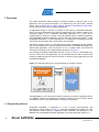
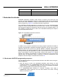
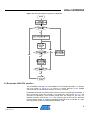
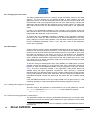
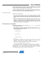
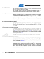
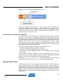
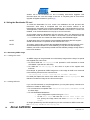
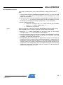
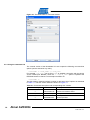
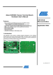
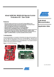
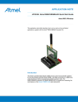
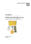
Atmel AVR2054: Serial Bootloader User Guide
Features
•
•
•
•
•
Description of serial bootloader
Hardware configuration instructions
Embedded bootloader description
Instructions on how to use the Bootloader PC tool
Creating SREC images
8-bit Atmel
Microcontrollers
Introduction
The serial bootloader is a stand-alone package consisting of two parts: embedded
bootloader that should be loaded to the flash memory of a supported MCU and the
PC based application that sends data to the embedded bootloader over serial link.
Application Note
The package contains all necessary sources for modifying and compiling the
embedded bootloader, including makefiles and projects files for various
development tool chains.
Chapter 1 provides an overview of serial bootloader and package’s contents as
well as a brief starting instruction. Following chapters cover more specific topics.
Hardware configuration including ports and fuse settings is covered in Chapter 2.
Chapter 3 describes embedded bootloader application and specifics of its different
kinds. Finally, Chapter 4 gives instructions on how to create an SREC image and
program a device with it, using the Bootloader PC tool.
Rev. 8390B-AVR-12/11
1 Overview
The serial bootloader allows loading of firmware images to devices from a PC
application over the serial connection. It is intended for use with Atmel® wireless
stacks, such as IEEE® 802.15.4 MAC, RF4CE, BitCloud® and BitCloud Profile Suite,
but can also be used with non-wireless applications.
An application image is received and written to the flash by embedded bootloader,
which must be programmed to the devices beforehand. The package contains precompiled images of the embedded bootloader application for a wide set of
configurations as well as its source code with projects files for different toolchains.
The embedded bootloader application can be built using Atmel AVR Studio® 5, IAR
Embedded Workbench®, or the command line. To enable this, the package provides
AVR Studio 5 project files, IAR™ project files, and makefiles.
A firmware image should be in the Motorola S-record hexadecimal format (SREC)
and may be transferred to a device programmed with the embedded bootloader by a
special host application. The host may be a PC or another MCU and should be
connected to the device via a serial interface as shown in Figure 1-1.
The package provides the Bootloader PC tool for a PC to act as a bootloader host.
The tool comes as a GUI application and a command line tool and is used to load
firmware images through the serial connection to devices pre-programmed with the
embedded bootloader.
Figure 1-1. General approach for using bootloader to program a device.
The Bootloader PC tool may also be used to initiate an Over-the-Air upgrade (OTAU)
of a ZigBee® network by transferring a firmware image to the OTAU server device
connected to the PC via a serial interface. See [3] for more detail.
1.1 Supported platforms
Embedded bootloader is supported on a set of Atmel microcontrollers and
development boards shown in Table 1-1. Note that embedded bootloader can work
with different serial interfaces. Supported serial interfaces are specified in the
Makefile of the embedded bootloader application at compile time (see Section 2.1).
2
Atmel AVR2054
8390B-AVR-12/11
Atmel AVR2054
Table 1-1. Supported MCUs and corresponding boards and modules.
MCU (Atmel)
Supported modules (Atmel)
Development board/kit
ATmega1281
ATmega2561
ATZB-24-B0
ATZB-24-A2
ATZB-A24-UFL
ATZB-900-B0
MeshBean,
(1)
RCB230/231/212
N/A
ATRF4CE-EK (RCB128RFA1
mounted on RCB Key Remote
Control board, RCB Sensor
Terminal Board or
RCB-BB),
ATAVR128RFA1-EK1
ATxmega256A3
ATxmega256D3
N/A
Atmel STK®600,
REB2xxED-EK
AT91SAM3S4C
N/A
deRFusb-23E00 (1)
ATmega128RFA1
Notes:
1. These are not Atmel products; see http://www.dresden-elektronik.de for
purchase.
1.2 Contents and structure
The package contains
• Embedded bootloader sources, including
o Source code and header files
o Makefiles for various configurations
o IAR projects (though not present for the bootloader for RF4CE
applications)
o Atmel AVR Studio 5 projects
• Pre-compiled firmware images of embedded bootloader
• Installation files for the Bootloader PC tool
• Documentation
Table 1-2 describes the serial bootloader file structure with paths given in regard to
the package’s root directory.
Table 1-2. Serial bootloader files and directories.
Path
Description
\Embedded_Bootloader_images\
Pre-compiled firmware images of
embedded bootloader
\Embedded_Bootloader_src\
Embedded bootloader sources
\Embedded_Bootloader_src\application\
Embedded bootloader source
code
\Embedded_Bootloader_src\ iar_projects\
IAR Embedded Workbench
project files for embedded
bootloader. Project files for
RF4CE version are not provided.
\Embedded_Bootloader_src\bootloader.aps
Atmel AVR Studio 4 project file for
the embedded bootloader
3
8390B-AVR-12/11
NOTE
Path
Description
\Embedded_Bootloader_src\as5_projects\
Atmel AVR Studio 5 project and
solution files for the embedded
bootloader
\Embedded_Bootloader_src\makefiles\
Makefiles for compiling the
embedded bootloader with IAR or
GCC compiler from the command
line or from AVR Studio 4 and 5
\PC_Bootloader_Setup\
Installation files for the Bootloader
PC tool
\Documentation\
Documentation folder
There are three types of embedded bootloader firmware distinguished by their
functionality: common bootloader, the bootloader with OTAU support for Atmel
BitCloud applications, and the bootloader for RF4CE applications. The latter two
provide extra functionality in addition to common bootloader features. For details see
sections 3.5 and 3.6.
1.3 Getting started
Serial bootloader is typically used in the following way:
1. Unpack the package to a folder on the PC hard drive.
2. Install the Bootloader PC tool. To launch the Bootloader PC tool you will need to
install Java®, if it is not installed on your PC.
3. Program the target device with an image of the embedded bootloader via JTAG,
unless it is already programmed.
4. Configure fuse bits for the bootloader support (see Section 2.2) if needed.
5. Connect the device via the serial interface to the PC.
6. Launch the Bootloader PC tool, specify the connection settings, the application
image in SREC format, and upload the image to the target device (see Section 4.1
for the detailed instruction).
2 Hardware configuration
Bootloader support may require changes in hardware configuration as described
below.
• Consider proper configuration of the serial interface that will be used to transfer a
firmware image from a PC to the device. Embedded bootloader and the Bootloader
PC tool can work with USART, SPI and USB, although the set of supported
interfaces depends on a platform
• Check fuse bits settings (Atmel AVR® and XMEGA® MCUs). An MCU must be
aware of the size of the memory occupied by the bootloader if it resides in the flash
and must start from the bootloader section rather than from the application section.
Section 2.2 describes fuses configuration for AVR and XMEGA highlighting the
differences where necessary
4
Atmel AVR2054
8390B-AVR-12/11
Atmel AVR2054
2.1 Serial interface
Table 2-1 describes default serial interfaces used by the embedded bootloader to
upload firmware images. The interface settings may be changed in the
configuration.h file of the embedded bootloader application (see Section 3.3).
Table 2-1. Default serial port settings for embedded bootloader.
Platform (Atmel)
Default port
Comment
USART0 on port D
For STK600, connect RXD/TXD
connectors with PD2/PD3 pins,
connect to PC via RS232
ATmega128RFA1 on
STK600
USART1
Connect RXD/TXD connectors with
PD2/PD3 pins, connect to PC via
RS232
ATmega128RFA1 on Red
Key Remote Control Board
(ATRF4CE-EK)
USART0
ATmega128RFA1 on
Sensor Terminal Board
(ATRF4CE-EK)
USB_FIFO
ATmega128RFA1 on
RCB-BB(ATRF4CE-EK)
USART1
ATxmega256A3/D3 on
STK600 and REB-CBB
(REB2xxED-EK)
ATmega1281/2561
(MeshBean)
USART1
For MeshBean and RCB attached to
an expander board, connect the
board to a PC via the USB port
AT91SAM3S4C
(deRFusb-23E00)
USB DFU
For USB sticks, attach the device to
the USB port on a PC
2.2 Fuse bits settings
NOTE
This section does not consider SAM3S, since this MCU does not have fuse bits.
Embedded bootloader firmware (if not yet loaded to a device) shall be uploaded over
the JTAG or ISP interface. Fuse bits must be configured correctly.
Recommended fuse bits for supported AVR microcontrollers are given in Table 2-2,
and fuse bits for supported XMEGA microcontrollers are given in Table 2-3. The
tables enumerate all fuse bits and show the resulting fuse bytes.
Table 2-2. Fuse bits on ATmega1281 and ATmega128RFA1.
Option
Common
bootloader
OTAU bootloader for Atmel
BitCloud applications
Bootloader for RF4CE
applications
BODLEVEL
Disabled
Disabled
Brown-out detection at
VCC = 1.8V
OCDEN
Disabled
Disabled
Disabled
JTAGEN
Enabled
Enabled
Enabled
SPIEN
Enabled
Enabled
Enabled
WDTON
Disabled
Disabled
Disabled
EESAVE
Disabled
Disabled
Enabled
5
8390B-AVR-12/11
Option
Common
bootloader
OTAU bootloader for Atmel
BitCloud applications
Bootloader for RF4CE
applications
Boot Flash size=2048 words
start address=$F800
Boot Flash size=2048
words start address=$F800
BOOTSZ
Boot Flash
size=1024
words start
address=$F
C00
BOOTRST
Enabled
Enabled
Enabled
CKDIV8
Enabled
Enabled
Enabled
CKOUT
Disabled
Disabled
Disabled
SUT_CKSE
L
Int. RC osc.;
Start-up
time: 6 CK +
65ms
Int. RC osc.; Start-up time: 6
CK + 65ms
Int. RC osc.; Start-up time:
6 CK + 0ms
Resulting
bytes
0xFF 0x9C
0x62
0xFF 0x9A 0x62
0xFE 0x92 0x42
Fuse bits configuration informs the MCU to start execution from the bootloader
section in memory instead of the application’s. On Atmel AVR microcontrollers the
bootloader is stored in the flash memory in the same address space as the
application. This reduces the amount of memory available for the application. The
fuse bits are also used to specify the amount of memory exclusively reserved for the
bootloader. Bootloader size may also vary depending on the bootloader type (for
example, the OTAU bootloader requires larger memory allocation than a bootloader
without OTAU support).
On XMEGAs, the embedded bootloader is kept in a separate storage, and so it is not
needed to specify the size of the bootloader section (all 256kb of flash are available
as the application memory).
Table 2-3. Fuse bits on Atmel ATxmega256A3 and Atmel ATxmega256D3.
Option
Required value
JTAGUSERID
0xFF
WDWP
8 cycles (8ms @ 3.3V)
WDP
8 cycles (8ms @ 3.3V)
DVSDON
OFF
BOOTRST
BODACT
BOOTLDR
Disabled
BODPD
Disabled
SUT
0ms
WDLOCK
OFF
JTAGEN
ON
EESAVE
OFF
BODLVL
1.6V
Resulting bytes
6
FUSEBYTE0
0xFF
FUSEBYTE1
0x00
Atmel AVR2054
8390B-AVR-12/11
Atmel AVR2054
Option
Required value
FUSEBYTE2
0xBF
FUSEBYTE4
0xFE
FUSEBYTE5
0xFF
3 Embedded bootloader
Embedded bootloader occupies a little amount of memory and serves the only
purpose, to load an application image from a serial interface and write it to the MCU’s
internal flash and/or EEPROM. A simple communication protocol is used to ensure
proper programming. Figure 3-1 illustrates bootloader organization.
The embedded bootloader application is provided as a set of pre-compiled firmware
images for various configurations and the source code. The user can immediately
start using boot loading by programming devices with the pre-compiled images. It is
also possible to modify the source code of the embedded bootstrap and compile it
using the appropriate toolchain.
Figure 3-1. Embedded bootloader architecture.
In addition to the common bootloader that simply programs application firmware to
the flash and EEPROM, embedded bootloader application may be built to support
additional features like Over-the-Air upgrade applied by BitCloud applications or
RF4CE features. The OTAU bootloader is able to load an application image, which
has been received by the application over the air and saved in an external memory
device, and program it into the internal flash memory (see Section 3.5). RF4CE
features are invoked by the application to enable a special type of the Over-the-Air
upgrade when the application image is replaced in memory simultaneously with
reception of the new image. For detail refer to Section 3.6.
3.1 Bootloader UART/SPI programming sequence
The embedded bootloader may process data received in the SREC format, using the
following algorithm:
1. After the device is reset, the embedded bootloader waits 200ms for each
configured interface for a HANDSHAKE_REQ data sequence to arrive via the
serial interface. If no HANDSHAKE_REQ is received, the embedded bootloader
jumps to the application’s entry point in the flash memory.
2. If a HANDSHAKE_REQ sequence is received, bootstrap code sends a
HANDSHAKE_CONF sequence over the serial interface and starts receiving
SREC records one by one.
7
8390B-AVR-12/11
3. For every valid SREC record the embedded bootloader responds with an ACK
data sequence over the serial interface.
4. In case of any error during loading process, the embedded bootloader sends a
NACK data sequence, then proceeds to (1).
On the PC side, the Bootloader PC tool performs the following actions:
1. The Bootloader PC tool sends a HANDSHAKE_REQ data sequence for 30
seconds with 200ms interval, waiting for a HANDSHAKE_CONF data sequence
between transmissions. Any reply except HANDSHAKE_CONF is ignored.
2. If HANDSHAKE_CONF is received, the PC bootloader starts sending data from
the SREC file via the serial link. Each record of the SREC file is converted to
binary representation before sending.
3. For every record sent the host expects an ACK over the serial link as a response.
If a NACK sequence is received or a timeout occurs, the PC bootloader aborts.
Serial data sequences used between the device and the host while boot loading:
•
•
•
•
HANDSHAKE_REQ: 0xB2, 0xA5, 0x65, 0x4B
HANDSHAKE_CONF: 0x69, 0xD3, 0xD2, 0x26
ACK: 0x4D, 0x5A, 0x9A, 0xB4
NACK: 0x2D, 0x59, 0x5A, 0xB2
Figure 3-2 illustrates the flowchart of the serial bootloader programming algorithm.
8
Atmel AVR2054
8390B-AVR-12/11
Atmel AVR2054
Figure 3-2. Serial bootloader programming algorithm.
3.2 Bootloader USB DFU specifics
The embedded bootloader for Atmel SAM3S microcontrollers operates in a different
way than shown in Figure 3-2 to conform to certain features of the SAM3S
microcontroller and development boards, on which it is hosted.
Embedded bootloader for SAM3S uses Device Firmware Upgrade (DFU) standard. A
DFU component should be included in the application (see Section 3.2.2.1). The
procedure of uploading a new firmware image does not change for the user. For
detailed instruction see Section 4.1.2. The remaining part of this section describes
implementation details of SAM3S embedded bootloader and is intended for users
who will possibly modify the embedded bootloader code.
9
8390B-AVR-12/11
3.2.1 Changing the reset vector
The Atmel SAM3S MCU does not contain a special bootloader section in the flash
memory1. The fuse settings do not indicate whether to start execution from the
application section or from the bootloader section and where this section starts. So if
the bootloader code is first programmed at the end of the flash memory and then the
application code is loaded into the remaining part of the flash memory, the MCU will
start code execution from the last loaded code after reset (that is, the application
code).
In order for the embedded bootloader to work correctly it must receive control first
after reset to be able to communicate with the host software and upload a new device
image before the application code is executed.
To achieve this, the embedded bootloader for SAM3S, during uploading, reassigns
the reset vector value (the MCU component that stores the address to start from
reset), setting it to its own starting address. Thus the MCU will always start execution
from the embedded bootloader, which, in turn, will pass control to the application
section upon completion.
3.2.2 DFU impact
Another feature involves notifying embedded bootloader that the PC tool is ready to
transfer a new firmware image to the device. For the Atmel AVR and XMEGA MCUs
the device must be reset before the new software upload can take place. Upon reset
the COM port assigned to the device on the PC is still enabled. The bootloader
receives control and waits for the uploading requests from the PC tool. However, to
reset a USB stick with SAM3S it should be removed and re-attached to the PC. This
may cause the PC to assign a different COM port to the device and stop the serial
communication with the device.
To prevent serial port reassignment when using SAM3S, the USB Device Firmware
Upgrade components based on [5] should be used. DFU components should be
included in both the embedded bootloader and the application code (see Section
3.2.1). The DFU component inserted in the application code should always be
enabled along with other application components. Upon receiving a command
indicating that a new firmware image is ready, it writes a special byte into the program
memory and initiates a device reset. After reset, the DFU component included in the
embedded bootloader checks this status byte and enters the new firmware upload
mode.
If the embedded bootloader is the only image loaded in the program memory, it will
constantly be ready to receive and upload a new firmware image from the host.
3.2.2.1 Adding DFU support to an application
The DFU class for the application is implemented on top of the USB driver. Set the
DFU_SUPPORT parameter to 1 in configuration.h file to enable DFU support:
#define DFU_SUPPORT 1
3.2.2.2 Not-responding application or absent DFU
The application loaded to the flash by embedded bootloader may not include a DFU
component as well as any special code to deal with PC tool’s requests. In other cases
1
A dedicated bootloader ROM section is included by individual manufactures for their
individual use.
10
Atmel AVR2054
8390B-AVR-12/11
Atmel AVR2054
when the DFU component is installed, it may stop responding due to application
failure. In these cases the device will not be able to process commands from the PC
tool and thus initiate reset and perform the firmware upgrade.
To load an image using bootloader into such device, connect JTAG’s PB7 pin to
ground and reset the device. On an Atmel SAM3S USB stick, these are the first two
pins of the JTAG port and so can be connected with a jumper wire.
3.2.2.3 Additional remarks
Below are some more features:
• If one loads a firmware image to a device via the embedded bootloader for SAM3S
and then reads the image using JTAG it will not equal the initial binary image. The
difference will be in the first four bytes where the bootloader replaced the reset
vector
• Both the embedded bootloader and an application cannot be loaded via JTAG. If
the device is first programmed with the embedded bootloader and then with the
application, by default the execution will start with the application code. And if the
application is programmed first, the embedded bootloader once programmed will
not be aware of the presence of the application
3.3 Configuration and compilation
Application configuration options are collected in the configuration.h file. Use this
file to configure the following:
• Serial interface used to receive a firmware image from the host: skip to the #ifdef
section regarding the MCU. For example, setting the USART1 port for an Atmel
ATmega128RFA1 MCU is done like this:
#ifdef ATMEGA128RFA1
// Use USART0
//#define USART0_
// Use USART1
#define USART1_
// Use USB_FIFO
//#define USB_FIFO_
#endif
• (Not applicable to SAM3S) Type of external flash device used to store the
application image during an over-the-air upgrade (TYPE_EXTERNAL_MEMORY
parameter). For example, the default setting is given by the following line:
#define TYPE_EXTERNAL_MEMORY Atmel25F2048
//#define TYPE_EXTERNAL_MEMORY Atmel45DB041
To use an alternative option, Atmel45DB041, uncomment the corresponding line.
Build configuration options for compilation with the make utility are contained in
makefiles in the makefiles directory, while build configuration options for compilation
in IAR Embedded Workbench are contained in IAR project files.
11
8390B-AVR-12/11
3.3.1 Compiler versions
The supported IAR compilers are IAR C/C++ Compiler for AVR v5.51.0.50312 and
IAR C/C++ Compiler for ARM® v6.20.3.52642.
The supported Windows® AVR GCC (WinAVR) version is 20100110, but it is
recommended to use the latest GCC compiler provided with Atmel AVR Studio 5.
3.3.2 Compilation from the command line and Atmel AVR Studio 4
When the embedded application is compiled using the command line or AVR Studio
4, compilation employs Makefile placed in the \Embedded_Bootloader_src\ folder to
determine what makefile from the makefiles directory shall be used. In Makefile,
specify PROJECT_NAME to choose among supported MCUs and CONFIG_NAME to select
a particular configuration.
To open the project in AVR Studio 4, launch the bootloader.aps file from the
\Embedded_Bootloader_src\ folder.
3.3.3 Compilation from Atmel AVR Studio 5
To compile the bootloader application in AVR Studio 5, open the appropriate project
file from the \Embedded_Bootloader_src\as5_projects directory, choose a
particular build configuration from the list on the toolbar, and select Build form the
Build menu.
3.4 Programming embedded bootstrap
If not already present on the MCU the firmware part of embedded bootloader (.hex
file) shall be uploaded to the device to enable programming over serial interface. AVR
Studio [1] and Atmel AVR JTAGICE mkll emulator [2] are recommended for loading
an embedded bootloader image. Note that to work correctly embedded bootloader
requires specific fuse bit settings that depend on the target platform and bootloader
functionality (see Section 2.2).
CAUTION
Setting JTAG fuse bits incorrectly may cause improper device functionality.
3.5 OTAU/BitCloud bootloader features
The OTAU bootloader is a version of embedded bootloader that can additionally be
used to upload BitCloud application to a device through Over-the-Air upgrade
(OTAU). Unlike the common bootloader, the OTAU bootloader contains a driver,
which is able to transfer an image from the external flash device to the MCU’s flash
memory as illustrated in Figure 3-3.
The OTAU bootloader is still able to write an application image received via a serial
interface to the flash as a common embedded bootloader. But it has more functions.
An application image, supporting OTAU typically includes the driver, which writes the
parts of the new application image received during the upgrade to an external flash
device. Once a new image is loaded, the application sets a new image available
status bit in EEPROM and resets. On startup after the reset the bootloader checks
this status bit and, if it is set, transfers the image from the external flash memory to
the internal MCU’s flash memory.
12
Atmel AVR2054
8390B-AVR-12/11
Atmel AVR2054
Figure 3-3. OTAU embedded bootloader architecture.
Over-the-Air Upgrade usually requires a special device that will distribute the
application image through the network. To start an upgrade, such device must be
connected to a PC with the Bootloader PC tool installed. The Bootloader PC tool
contains the OTAU tab, which is used to initiate and control an upgrade. For further
details on the topic of OTAU refer to [3].
3.6 Bootloader configuration for RF4CE
The embedded bootloader configuration to support RF4CE applications is primarily
the same as for the common embedded bootloader, but it also provides additional
APIs to support Over-the-Air upgrade and the persistent data storage feature that can
be used by RF4CE applications. The APIs provided by the serial bootloader and the
additional APIs for RF4CE, both make use of self-programming functions. These
extra APIs to support Over-the-Air upgrade and persistent data storage are written
into the RWW section (the bootloader section). These APIs can also be used by other
applications for the purposes as listed below:
•
•
•
•
Storing the persistent data (for example, NIB) in the flash memory
Clearing the persistent data (for example, clear NIB)
Temporarily storing the updated image in the flash memory
Replacing the existing application image with the updated image (swapping
functionality)
Please note that bootloader configuration for RF4CE applications do not use any
external flash for the firmware update. Instead, it uses the unutilized internal flash
memory for the Over-the-Air upgrade and persistent data storage.
Please see rf4ceFlash.h and rf4ceFlash.c files for more details on the API and its
implementation. Additionally, refer to [4] for more detail regarding RF4CE.
4 Bootloader PC tool
The Bootloader PC tool is a PC application that is used to load a firmware image to a
device programmed with the embedded bootloader code. A device should be
connected to a COM port. Source firmware images shall be in the Motorola S-record
(SREC) format. Such images are created during compilation further to .hex and .elf
images. A device must be programmed with an image of the embedded bootloader
application, which will receive data sent by the Bootloader PC tool and write it to the
device’s flash.
13
8390B-AVR-12/11
Another use of the Bootloader PC tool is initiating Over-the-Air Upgrade. This
document does not cover this usage of the tool. A complete guide to Over-the-Air
Upgrade of ZigBee networks is given in [3].
4.1 Using the Bootloader PC tool
To install the Bootloader PC tool, launch the installation file and proceed with
instructions. After setup is completed both GUI and console versions of the
bootloader are extracted to the provided installation path. The Bootloader PC tool is a
Java application, and to launch it Java must be installed on the host PC. If Java is not
installed, it can be downloaded from http://java.com/en/download/.
As a firmware image the Bootloader PC tool requires a file in the Motorola S-record
hexadecimal format, also known as SREC or S19 format. Such file names have the
.srec extension and can contain both flash memory and EEPROM images.
NOTE
An application that is to be loaded by the embedded bootloader with DFU support
should include the DFU component as well. See Section 3.2.2.1.
NOTE
To program a device that contains the embedded bootloader with DFU support (such
as the embedded bootloader for Atmel SAM3S) you may also use the third-party
software, since DFU components provided with this software package closely adhere
to the DFU standard.
4.1.1 Generating SREC image
4.1.1.1 Using GCC tools
An SREC image can be generated from initial binary image with the help of a special
tool supplied with a tool chain.
• For Atmel AVR use avr-objcopy.exe tool provided in AVR toolchain for Atmel
AVR Studio 5 (as well as in WinAVR)
• For ARM use arm-elf-objcopy.exe tool, which is a part of the Yagarto GCC
toolchain
For example, to generate an SREC image from a .hex image for AVR run a command
in the following format from the command line:
avr-objcopy.exe -O srec --srec-len 128 <srcFile> <destFile>
For ARM just replace the name of the AVR tool with arm-elf-objcopy.exe. Note
that this tool takes an image in the .elf format as input.
4.1.1.2 Using IAR tools
If you use IAR toolchain to compile applications you may also specify a directive for
the linker to create an SREC image:
• For command line compilation add -Omotorola-s28=<path>/<fileName>.srec to
the linker flags
• For IAR Embedded Workbench
o Open configuration’s options and go to Linker
o On the Extra Output tab check the Generate extra output file
box, specify the image name and select motorola-s28 as Output
format
NOTE
14
An image generated by the IAR compiler may be also converted to SREC format with
the avr-objcopy.exe or arm-elf-objcopy.exe.
Atmel AVR2054
8390B-AVR-12/11
Atmel AVR2054
4.1.2 Programming a device
To program a wireless device using serial bootloader the following steps shall be
done:
1. Connect a device with the embedded bootloader firmware on it to a PC via serial
connection. For detail refer to documentation of the development kit or the
software provided with it.
2. For the GUI version of serial bootloader run the application by double-clicking the
bootloadergui.exe file. For the console version just start command line from the
Bootloader PC tool installation directory (see Section 4.1.3 for more detail).
3. Specify uploading parameters.
a. Select the connection type. For all devices except Atmel SAM3S
select Serial, while for SAM3S select USB.
b. Select the port from the list.
NOTE
There is a restriction on the size of firmware downloadable by serial booting process.
Serial bootloader cannot rewrite the area where the bootstrap code resides.
4. Press the Upload button if Bootloader PC GUI tool is used. For the console
bootloader press Enter on the keyboard to start uploading.
5. Press the HW reset button on the device if requested. The Bootloader PC tool will
be waiting for approximately 30 seconds for the button to be released. If this does
not happen, programming will be aborted.
6. The Bootloader PC tool will indicate the programming progress. Once loading is
finished successfully, the device will be restarted automatically. If loading fails, the
Bootloader PC tool will indicate the reason. In case the new image upload fails (for
example, because of random communication errors) the device should be reprogrammed. It the reprogramming does not resolve the issue then the previously
programmed code image in the device may be corrupted. The device should be
erased and reprogrammed via JTAG.
15
8390B-AVR-12/11
Figure 4-1. The Bootloader PC tool main window.
4.1.3 Using the command line
The console version of the Bootloader PC tool accepts the following command-line
options (can be entered in any order):
bootloader –f <file_name> –p <com_port>
For example, <com_port> can be set to COM3 to establish connection with the device
via the COM3 port. Besides, when the -e <eeprom_size> option is specified the
EEPROM section is cleared. To see help information run:
bootloader -h
The GUI version contains interface controls for the same set of options as described
in Table 4-1. The GUI version window is shown on Figure 4-1.
Table 4-1. Command-line options and corresponding GUI controls.
Command line option
16
GUI control
Description
-f
Select SREC file
Path to the firmware image of SREC
format to be loaded to device
-p
Select Serial port
COM port number
-e
EEPROM Erase
Clean up EEPROM section. EEPROM size
shall be specified
Atmel AVR2054
8390B-AVR-12/11
Atmel AVR2054
5 References
[1] Atmel AVR Studio User Guide. Available in HTML Help with the product.
[2] JTAGICE mkII Quick Start Guide
[3] AVR2058; BitCloud OTAU User Guide; Application Note; Rev. 8426A-AVR08/11; Atmel Corporation
[4] AVR2102; RF4Control - User Guide; Application Note; Rev. 8357B-AVR08/11; Atmel Corporation
[5] Universal Serial Bus Device Class Specification for Device Firmware
Upgrade
17
8390B-AVR-12/11
6 Table of contents
Features ............................................................................................... 1
Introduction ......................................................................................... 1
1 Overview ........................................................................................... 2
1.1 Supported platforms ............................................................................................ 2
1.2 Contents and structure ........................................................................................ 3
1.3 Getting started ..................................................................................................... 4
2 Hardware configuration................................................................... 4
2.1 Serial interface..................................................................................................... 5
2.2 Fuse bits settings................................................................................................. 5
3 Embedded bootloader ..................................................................... 7
3.1 Bootloader UART/SPI programming sequence .................................................. 7
3.2 Bootloader USB DFU specifics ........................................................................... 9
3.2.1 Changing the reset vector ....................................................................................... 10
3.2.2 DFU impact ............................................................................................................. 10
3.3 Configuration and compilation........................................................................... 11
3.3.1 Compiler versions.................................................................................................... 12
3.3.2 Compilation from the command line and Atmel AVR Studio 4................................. 12
3.3.3 Compilation from Atmel AVR Studio 5..................................................................... 12
3.4 Programming embedded bootstrap................................................................... 12
3.5 OTAU/BitCloud bootloader features.................................................................. 12
3.6 Bootloader configuration for RF4CE ................................................................. 13
4 Bootloader PC tool ........................................................................ 13
4.1 Using the Bootloader PC tool ............................................................................ 14
4.1.1 Generating SREC image ......................................................................................... 14
4.1.2 Programming a device............................................................................................. 15
4.1.3 Using the command line .......................................................................................... 16
5 References...................................................................................... 17
6 Table of contents ........................................................................... 18
18
Atmel AVR2054
8390B-AVR-12/11
Atmel Corporation
2325 Orchard Parkway
San Jose, CA 95131
USA
Tel: (+1)(408) 441-0311
Fax: (+1)(408) 487-2600
www.atmel.com
Atmel Asia Limited
Unit 01-5 & 16, 19F
BEA Tower, Milennium City 5
418 Kwun Tong Road
Kwun Tong, Kowloon
HONG KONG
Tel: (+852) 2245-6100
Fax: (+852) 2722-1369
Atmel Munich GmbH
Business Campus
Parkring 4
D-85748 Garching b. Munich
GERMANY
Tel: (+49) 89-31970-0
Fax: (+49) 89-3194621
Atmel Japan
9F, Tonetsu Shinkawa Bldg.
1-24-8 Shinkawa
Chou-ku, Tokyo 104-0033
JAPAN
Tel: (+81) 3523-3551
Fax: (+81) 3523-7581
© 2011 Atmel Corporation. All rights reserved.
®
®
®
®
®
®
Atmel , Atmel logo and combinations thereof, AVR , AVR Studio , BitCloud , STK , XMEGA , and others are registered trademarks or
®
trademarks of Atmel Corporation or its subsidiaries. Windows and others are registered trademarks or trademarks of Microsoft
®
Corporation in U.S. and or other countries. ARM is a registered trademark of ARM Ltd. Other terms and product names may be
trademarks of others.
Disclaimer: The information in this document is provided in connection with Atmel products. No license, express or implied, by estoppel or otherwise, to
any intellectual property right is granted by this document or in connection with the sale of Atmel products. EXCEPT AS SET FORTH IN THE ATMEL
TERMS AND CONDITIONS OF SALES LOCATED ON THE ATMEL WEBSITE, ATMEL ASSUMES NO LIABILITY WHATSOEVER AND DISCLAIMS
ANY EXPRESS, IMPLIED OR STATUTORY WARRANTY RELATING TO ITS PRODUCTS INCLUDING, BUT NOT LIMITED TO, THE IMPLIED
WARRANTY OF MERCHANTABILITY, FITNESS FOR A PARTICULAR PURPOSE, OR NON-INFRINGEMENT. IN NO EVENT SHALL ATMEL BE
LIABLE FOR ANY DIRECT, INDIRECT, CONSEQUENTIAL, PUNITIVE, SPECIAL OR INCIDENTAL DAMAGES (INCLUDING, WITHOUT LIMITATION,
DAMAGES FOR LOSS AND PROFITS, BUSINESS INTERRUPTION, OR LOSS OF INFORMATION) ARISING OUT OF THE USE OR INABILITY TO
USE THIS DOCUMENT, EVEN IF ATMEL HAS BEEN ADVISED OF THE POSSIBILITY OF SUCH DAMAGES. Atmel makes no representations or
warranties with respect to the accuracy or completeness of the contents of this document and reserves the right to make changes to specifications and
product descriptions at any time without notice. Atmel does not make any commitment to update the information contained herein. Unless specifically
provided otherwise, Atmel products are not suitable for, and shall not be used in, automotive applications. Atmel products are not intended, authorized, or
warranted for use as components in applications intended to support or sustain life.
8390B-AVR-12/11