1
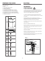
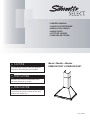
• OWNER’S MANUAL
• GUIDE DU PROPRIÉTAIRE
• MANUAL DEL USARIO
• RANGE HOOD
• HOTTE DE CUISINE
• CAMPANA DE COCINA
CAUTION
Read and follow all safety rules and operating
instructions before first use of this product.
Model • Modéle • Modelo
DWRH301SSST & DWRH361SSST
PRECAUTION
Veuillez lire attentivement les consignes de
sécurité et les instructions d’utilisation avant
l’utilisation initiale de ce produit.
PRECAUCIÓN
Lea y observe todas las reglas de seguridad y las
instrucciones de operación antes de usar esto
producto por primera vez.
V2.05.12.DM
Model Number:
Serial Number:
Date of Purchase:
Dealer:
PLEASE STAPLE YOUR SALES RECEIPT TO THE INSIDE FRONT
COVER
TABLE OF CONTENTS
ENGLISH
Important Safety Instructions ................................ 2
Ducting................................................................... 3
Installation.............................................................. 4-8
Operation .............................................................. 9
Bulb Replacement ............................................... 10
Cleaning and Maintenance ................................... 10
Troubleshooting .................................................... 11
Warranty ................................................................ 12
FRANÇAIS
Consignes importantes relatives à la sécurité ......
Conduits ...............................................................
Installation ............................................................
Fonctionnement ....................................................
Remplacement de l'ampoule ................................
Nettoyage et entretien ..........................................
Dépannage ...........................................................
Garantie ................................................................
14
15
16-20
21
22
22
23
24
ESPAÑOL
Instrucciones de Seguridad Importantes ...............
Ubicar el Conducto.................................................
Instalción................................................................
Operación...............................................................
Reemplazar la Bombilla ........................................
Limpieza y Mantenimiento ....................................
Resolución de Problemas .....................................
Garantía ...............................................................
DWRH301SSST & DWRH361SSST
1
26
27
28-32
33
34
34
35
36
IMPORTANT SAFETY INSTRUCTIONS
READ AND SAVE THESE INSTRUCTIONS
FOR DOMESTIC COOKING ONLY
1. Read all instructions before using the appliance
2. Install or locate this appliance only in accordance with the
provided installation instructions.
3. Clean range hoods frequently. Grease should not be allowed
to accumulate on the range hood or filters.
4. Always turn the fan on when flambéing foods on the range.
5. This appliance is suitable for use in combination with both
gas and electric cooking equipment.
6. Use care when cleaning the range hood filter. Corrosive
cleaning agents, such as lye-based oven cleaners, may damage the filter.
GROUNDING INSTRUCTIONS
1) If it is necessary to use an extension cord, use only a
3-wire extension cord that has a 3-blade electrical plug,
and 3-slot power outlet that will accept the plug on the appliance. The marked rating of the extension cord must be
equal to or greater than the electrical rating of the appliance. Otherwise, do not use an extension cord.
WARNING
TO REDUCE THE RISK OF FIRE, ELECTRIC SHOCK,
OR INJURY TO PERSONS, OBSERVE THE FOLLOWING:
1. Use this unit only in the manner intended by the manufacturer. If you have questions, contact the manufacturer at
the address or telephone number listed in the warranty.
2. Before servicing or cleaning the unit, switch the power
off at the service panel. Lock and tag the service panel to
prevent power from being switched on accidentally.
3. Installation work and electrical wiring (including switch
location) must be done by a qualified person(s) in accordance with all applicable codes and standards.
4. To prevent backdrafting, provide sufficient air for proper
combustion and exhausting of gases through the flue (vent)
of the fuel burning equipment. Follow combustion equipment standards such as those published by the National
Fire Protection Association (NFPA,) the American Society
for Heating, Refrigeration and Air Conditioning Engineers
(ASHRAE,) and local codes.
5. This product may have sharp edges. Be careful to avoid
cuts and abrasions during installation and cleaning.
6. When cutting or drilling into a wall or ceiling, do not damage electrical wiring and other hidden utilities.
7. Fans must always be vented to the outdoors.
8. Use only metal ductwork.
9. This unit must be grounded.
TO REDUCE THE RISK OF A RANGE TOP GREASE
FIRE:
1. Never leave surface units unattended. Rapid boiling
causes smoke and grease spills that may ignite. Heat oils
slowly on a low or medium setting.
2. Always turn hood ON when cooking at high heat or when
flambéing food.
3. Clean the ventilating fans frequently. Do not allow grease
to accumulate on the fan, fan blades and filter.
4. Use the proper pan size. Always use cookware appropriate for the size of the surface element.
WARNING
TO REDUCE THE RISK OF INJURY TO PERSONS IN
THE EVENT OF A RANGE TOP GREASE FIRE, OBSERVE THE FOLLOWING:*
1. SMOTHER FLAMES with a close-fitting lid, cookie sheet,
or metal tray, then turn off the burner. BE CAREFUL TO
AVOID BURNS. If the flames do not go out immediately,
EVACUATE THE AREA AND CALL THE FIRE DEPARTMENT.
2. NEVER PICK UP A FLAMING PAN. You may get burned
or spread the fire.
3. DO NOT USE WATER, including wet dishcloths or towels; a violent steam explosion could result.
4. Use an extinguisher ONLY if:
A. You know you have a Class ABC extinguisher and you
already know how to operate it.
B.The fire is small and contained in the area where it
started.
C. The fire department has already been called.
D. You can fight the fire with your back to an exit.
*Based on “Kitchen Fire Safety Tips” published by NFPA.
CAUTION
1. To reduce risk of fire and to properly exhaust air, be sure
to duct air outside. Do not vent exhaust air into spaces
within walls or ceilings, or into attics, crawl spaces, or
garages.
2. Take care when using cleaning agents or detergents.
3. Avoid using food products that produce flames under the
range hood.
4. For general ventilating use only. Do not use to exhaust
hazardous or explosive materials and vapors.
5. To avoid motor bearing damage and noisy / unbalanced
impellers, keep drywall spray, construction dust, etc off the
power unit.
6. Your hood motor has a thermal overload which will
automatically shut off the motor if it becomes overheated.
The motor will restart when it cools down. If the motor continues to shut off and restart, have the hood serviced.
7. To best capture cooking impurities, the bottom of the
hood should be a minimum of 26” and a maximum of 34”
above the cooking surface.
8. Two installers are recommended because of the large
size and weight of this hood.
9. Please read specification label on product for further
information and requirements.
Installer: Leave this manual with the homeowner.
Homeowner: Cleaning, maintenance, and operating instructions begin on page 3.
2
PREPARE THE HOOD
DUCTING
Unpack hood and check contents.
You should receive:
1 - Hood
2 - (A) Decorative Flue Assembly
1 - Parts Bag containing:
2 - (B) Flue Mounting Bracket
2 - (C) Mounting Screws (M3 x 8mm Pan Head)
2 - (D) Mounting Screws (M4 x 8mm Round Head)
2 - (E) Mounting Screws (ST4 x 12mm Self Tapping)
2 - (F) Mounting Screws (ST4 x 35mm Self Tapping)
4 - Drywall Anchors [(G) 6 x 30mm & (H) 8 x 35mm]
1 - Installation Instructions
WARNING!
FIRE HAZARD
1. NEVER implement ducting in a space between walls, crawl
spaces, attics or garages. All exhaust must be vented outside.
Use metal ducting only. Fasten all connections with sheet
metal screws and certified silver tape or duct tape.
2. See Fig. 1 below for placement of ducting and electrical
cutout in wall. For a non-ducted installation, DO NOT cut a duct
access hole.
Determine whether the hood will discharge vertically or
horizontally. For vertical or horizontal discharge, run ductwork
between the hood location and roof cap or wall cap.
A minimum 6” round duct must be used to maintain maximum
airflow efficiency.
A
Always use rigid type metal ducts only.
Whenever possible, reduce the number of transitions and turns
in the ducting. If a long duct length is required, increase the
duct size from 6” to 7”.
If elbows or bends are required; install them as far away from
the hood as possible.
B
Minimum mounting height between the range and the bottom
of the hood should be no less than 26”.
C
Maximum mounting height between the range and the bottom
of the hood should be no more than 34”.
D
FIG. 1
E
ROOF CAP
ROUND
DUCT
F
DECORATIVE
FLUE
WALL CAP
ROUND ELBOW
G
6" ADAPTER
HOOD
26"~34"ABOVE
COOKING SURFACE
H
3
INSTALLATION INSTRUCTIONS
1) MARK REFERENCE POINTS ON WALL
FIG. 2
The bottom of the range hood must sit between 26”
(min) and 36” (max) above the stove top. The screw
holes must be situated 9 1/2” above the point where
the bottom of the range hood will hang. The screw
holes for mounting the range hood must be 7 7/8”
apart. Refer to Fig. 2 and mark these reference points
on the wall before installing the range hood. Then, drill
2 screws into the wall but not tightly: you must leave
some of the screw (roughly half an inch) out of the wall
until after the range hood is mounted.
CEILING
F&H
F&H
7-7/8”
9-1/2”
26” min
34” max
2) MOUNTING THE RANGE HOOD ON THE
WALL
FIG. 3
Before mounting the range hood on the wall please take out
the filters and remove any plastic or styrofoam found inside
the range hood (see Fig. 3 and Fig. 4.) Leave the filters out
until Step 3 is finished.
FIG. 4 - PEEL OFF PLASTIC FROM THE FLUES
Separate the extension flue by
pulling it upward.
A
Remove the plastic
found on the flues.
Remove filters and
styrofoam pieces
from inside the
rangehood.
16-1/2”
1.Push in tab
17-1/2”
2.Pull downward
4
INSTALLATION INSTRUCTIONS
3) MOUNTING TO THE WALL
Position the range hood by hanging it onto the screws. Once it is
level, tighten the screws all the way from inside the range hood (Fig
5.) Please note: a stubby screwdriver may be required to access the
screws from inside the range hood. Once the range hood is securely
fastened, the filters can be put back in. At this point, the range hood
should match Fig. 6.
F&H
FIG. 5
Please tighten the 2 screws from the inside.
FIG. 6
CEILING
F&H
F&H
7-7/8”
9-1/2”
26” min
34” max
5
INSTALLATION INSTRUCTIONS
4) MOUNTING THE DECORATIVE FLUE (REQUIRES 2 PEOPLE)
Before you mount the decorative flue to the range hood, fasten the exhaust tubing to
the blower housing and make sure all ducting is correct (see Fig. 7.) Have a qualified
electrician connect the power supply (see Fig. 8.) Next, fasten the decorative flue onto
the range hood. DO NOT SEPARATE THE EXTENSION FLUE! Have one person hold
the flue and the other person align the holes on the decorative flue with the holes on
the range hood brackets. Fasten the 2 screws on each side (see Fig. 9.)
FIG. 7
CEILING
FIG. 8 - Wiring diagram
WALL
ELECTRICAL
ACCESS
Exhaust
tubing/duct
Blower
Housing
Connect house power cable to range hood wiring,
Ground Wire: GREEN
/ Fire Wire : BLACK
1 Zero Line : WHITE
FIG. 9 - Side of unit
FINAL
STEP.1
Flu
WALL
WALL
Align holes
Rangehood
Flu
Rangehood
C
STEP.2
Tighten screw
on each side
6
INSTALLATION INSTRUCTIONS
5) MOUNTING BRACKET INSTALL
Locate the mounting bracket and center it on the wall just below the ceiling
(Option A) or on the ceiling with the hooks facing downward (Option B) using 2
screws (see Fig. 10.) Once the bracket has been mounted on the wall or ceiling,
raise the extension flue toward the ceiling and line up the holes in the flue with
the holes in the mounting bracket. Secure the extension flue by fastening it with
2 screws on each side (see Fig. 11.) Final install see Figs. 12 and 13.
FIG. 10
FIG. 11
CEILING
CEILING
D
Fix the
mounting
bracket to
the wall or
ceiling using
2 screws and
2 drywall
anchors (E & G.)
Raise
extension
flue toward
ceiling and
align the holes
then secure it
in place with 2
screws on each
side (D.)
E&Gx2
FIG. 13 - Bracket on ceiling (Option B)
FIG. 12 - Bracket on wall (Option A)
2. Align holes and secure
flue to the bracket with 2
screws on each side
2. Align holes and secure
flue to the bracket with 2
screws on each side
8-3/4”
6-1/2”
8-3/4”
6-1/2”
D
E&Gx2
D
D
D
1. Mount these screws to the wall
to secure the mounting
bracket
E&Gx2
1. Mount these screws to the
ceiling to secure the mounting
bracket.
7
D
INSTALLATION INSTRUCTIONS
5) FINAL INSTALLATION IMAGE
CEILING
8-3/4”
6-1/2”
FIG. 14
D
E & G x2
D
C
C
7-7/8”
F&Hx2
9-1/2”
26” min
34” max
8
OPERATION
Always turn the hood ON before cooking in order to establish
an air flow in the kitchen. After turning off the range, let the
hood run for a few minutes to clear the air.
Fan
Your Silhouette Select™ range hood offers 3 fan settings:
low, medium and high. To activate the fan press the fan button
and the fan starts at the low setting and the corresponding icon
appears on the LED display. Press the fan button again and
the blower increases to the medium speed. Press a third time
for the highest speed and a fourth time to turn the fan off.
HEAT SENTRY™
The hood is equipped with a Heat Sentry™ thermostat. This
safety device will turn on or speed up the fan if it senses
excess heat above the cooking surface. If the fan is not on, or
if it is running at low speed, the Heat Sentry™ will override the
normal fan control and run the fan on the high speed. When
the temperature level drops to normal levels, the fan will return
to its original setting.
Icon for low speed
Icon for medium speed
Icon for high speed
Operate the hood as follows:
Power
To activate the range hood, press the power button. Once
activated, the buttons and LED light up.
Light
The Silhouette Select™ range hood are equipped with 3 light
settings High, Low and Off. Press the light icon once and the
20w halogen bulbs turn on providing full task lighting. Press
the icon again and this reduces the illumination to 50%. Press
the icon a third time to turn the lights off.
Filter
After 100 hours, the filter icon lights up and the user must remove the filter, clean it and replace it in order to reset the icon.
Press and hold the power button for 3 seconds to reset after
cleaning the filter.
Timer
Silhouette Select™ range hoods include a convenient feature
that allows the range hood to continue to run for an additional
5 minutes to expel residual vapors and odors after cooking.
When the timer button is pressed once the current fan speed
will continue to run for a duration of 5 minutes and the timer
icon appears on the LED display. Push the timer button a
second time to cancel the timer and remove the icon from the
LED display.
9
CLEANING & MAINTENANCE
BULB REPLACEMENT
The mesh filters are intended to trap residue and grease
produced during cooking process. To ensure optimal performance, appearance, and a sanitary cooking environment,
clean the filters, fan and grease laden surfaces regularly. Use
only a clean cloth and mild detergent solution on stainless
steel and painted surfaces. Do not use corrosive or abrasive
cleaning agents or steel wool or scouring pads as these will
scratch the surface. Do not use cleaning products that use
chlorine bleach or orange cleaners.
CAUTION: the light bulbs and glass cover become extremely
hot when running. Shut off the lights and allow them to cool
prior to changing the bulb. Failing to do so could result in
serious burns. Turn off power to the unit before replacing bulb.
Be careful around sharp edges.
The grease filters, bottom panel surrounding the grease filters,
and the blower should be cleaned frequently. When washing
by hand use warm soapy (mild detergent) water. The grease
filter and blower wheels are dishwasher safe.
The motor is permanently lubricated and never needs oiling. If
the motor bearings make unusual or excessive noise, call for
service at 1-800-263-2629.
Hood Cleaning
FIG. 15
Stainless steel is one of the easiest materials to keep
clean. Occasional care will help preserve its fine appearance.
Cleaning tips:
Hot water with soap or detergent is all that is usually needed.
Follow all cleaning with rinsing with clear water. Wipe dry with
a clean, soft cloth to avoid water marks.
For discolorations or deposits that persist, use a nonscratching household cleanser or stainless steel polishing
powder with a little water and a soft cloth.
For stubborn messes, use a plastic scouring pad or soft bristle
brush together with cleaning solution and water. Rub lightly
in direction of polishing lines or “grain” of the stainless finish.
Avoid using too much pressure which may alter the surface.
FIG. 16
1. Remove the grease filters.
DO NOT allow deposits to remain for long periods of time.
DO NOT use ordinary steel wool or steel brushes. Small bits
of steel may adhere to the surface causing rust.
DO NOT allow salt solutions, disinfectants, bleaches, or
cleaning compounds to remain in contact with stainless steel
for extended periods.
2. Reach within the unit and push out the lamp housing
towards you. See Fig. 15.
3. Using a small, flat-head screw driver pop off the glass
plate. See Fig. 16 above.
4. Remove the burnt out 2-pronged 20 watt Halogen bulb.
Replace with a new 20 watt Halogen bulb. Wipe the new bulb
with a clean cloth before replacing the cover.
Many of these compounds contain chemicals which may be
harmful.
5. Caution: the lights are designed for 20 watt Halogen bulbs
only. Replacing with high wattage bulbs can result in
damage to the range hood or fire and not recommended
Rinse with water after exposure and wipe dry with a clean
cloth.
6. Replace lamp cover and press lamp housing back into
place.
Painted surfaces should be cleaned with warm water and mild
detergent only.
10
TROUBLESHOOTING
Issue
Cause
What to do
After installation, the unit
doesn’t work.
1. The power source is not turned ON.
2. The power line and the cable locking
connector are not connecting properly.
1. Call for service.
2. Call for service.
Light works, but motor is
not turning.
1. The blower is defective, possibly
seized.
2. Damaged capacitor.
1. Call for service.
2. Call for service.
The unit is vibrating.
1. The blower is not secure in place.
2. Damaged blower wheel.
3. The hood is not secured in place.
1. Tighten the blower in place.
2. Change the blower.
3. Check the installation of the hood.
The motor is working,
but the lights are not.
1. Defective halogen bulb.
1. Change the halogen bulb.
The hood is not venting
out properly.
1. The hood might be hanging to high from
the cook top.
2. The wind from the opened windows or
opened doors in the surrounding area
are affecting the ventilation of the hood.
3. Blockage in the duct opening or duct
work.
4. The direction of duct opening is against
the wind.
5. Using the wrong size of ducting.
1. Adjust the distance between the range
and the bottom of the hood within 26”~34”
2. Close all windows and doors to eliminate
the outside wind flow.
3. Remove all the blocking from the duct
work or duct opening.
4. Adjust the duct opening direction.
5. Change the ducting to at least 6” or
higher.
Metal filter is vibrating.
1. Verify spring clip is not broken.
2. Replace the metal filter.
1. Spring clip is broken.
2. Metal filter is loose.
11
LIMITED IN-HOME APPLIANCE WARRANTY
This quality product is warranted to be free from manufacturer’s defects in material and workmanship, provided that the unit is used under the normal operating
conditions intended by the manufacturer.
This warranty is available only to the person to whom the unit was originally sold by Danby Products Limited (Canada) or Danby Products Inc. (U.S.A.) (hereafter
“Danby”) or by an authorized distributor of Danby, and is non-transferable.
TERMS OF WARRANTY
Consumable parts (ie. light bulbs, filters, glass trays, etc.) are warrantied for thirty (30) days from purchase date, with no extensions provided.
First 24 Months
During the first twenty four (24) months, any functional parts of this product found to be defective, will be repaired or replaced, at
warrantor’s option, at no charge to the ORIGINAL purchaser.
To obtain
Service
Danby reserves the right to limit the boundaries of “In Home Service” to the proximity of an Authorized Service Depot. Any appliance
requiring service outside the limited boundaries of “In Home Service” ,it will be the consumer’s responsibility to transport the appliance (at
their own expense) to the original retailer (point of purchase) or a service depot for repair. See “Boundaries of In Home Service” below.
Contact your dealer from whom your unit was purchased, or contact your nearest authorized Danby service depot, where service
must be performed by a qualified service technician.
If service is performed on the unit by anyone other than an authorized service depot, or the unit is used for commercial application, all
obligations of Danby under this warranty shall be void.
Boundaries of
In Home Service
If the appliance is installed in a location that is 100 kilometers (62 miles) or more from the nearest service center your unit must be
delivered to the nearest authorized Danby Service Depot, as service must only be performed by a technician qualified and certified for
warranty service by Danby. Transportation charges to and from the service location are not protected by this warranty and are the
responsibility of the purchaser.
EXCLUSIONS
Save as herein provided, Danby, there are no other warranties, conditions, representations or guarantees, express or implied, made or intended by Danby or its
authorized distributors and all other warranties, conditions, representations or guarantees, including any warranties, conditions, representations or guarantees
under any Sale of Goods Act or like legislation or statue is hereby expressly excluded. Save as herein provided, Danby shall not be responsible for any damages
to persons or property, including the unit itself, howsoever caused or any consequential damages arising from the malfunction of the unit and by the purchase of
the unit, the purchaser does hereby agree to indemnify and hold harmless Danby from any claim for damages to persons or property caused by the unit.
GENERAL PROVISIONS
No warranty or insurance herein contained or set out shall apply when damage or repair is caused by any of the following:
1) Power failure.
2) Damage in transit or when moving the appliance.
3) Improper power supply such as low voltage, defective house wiring or inadequate fuses.
4) Accident, alteration, abuse or misuse of the appliance such as inadequate air circulation in the room or abnormal operating conditions
(extremely high or low room temperature).
5) Use for commercial or industrial purposes (ie. If the appliance is not installed in a domestic residence).
6) Fire, water damage, theft, war, riot, hostility, acts of God such as hurricanes, floods etc.
7) Service calls resulting in customer education.
8) Improper Installation (ie. Building-in of a free standing appliance or using an appliance outdoors that is not approved for outdoor application).
Proof of purchase date will be required for warranty claims; so, please retain bills of sale. In the event warranty service is required, present this document to our
AUTHORIZED SERVICE DEPOT.
Warranty Service
In-home
Danby Products Limited
PO Box 1778, Guelph, Ontario, Canada N1H 6Z9
Telephone: (519) 837-0920 FAX: (519) 837-0449
1-800-263-2629
04/09
12
Danby Products Inc.
PO Box 669, Findlay, Ohio, U.S.A. 45840
Telephone: (419) 425-8627 FAX: (419) 425-8629
Model • Modéle • Modelo
DWRH301SSST & DWRH361SSST
HOOD RANGE
HOTTE DE CUISINE
The model number can be found on the serial plate
located on the back panel of the unit.
All repair parts available for purchase or special
order when you visit your nearest service depot. To
request service and/or the location of the service
depot nearest you, call the TOLL FREE number.
Le numéro de modèle se trouve sur la plaque
signalétique au dos de l’unité.
Vous pouvez vous procurer/commander toute
pièce de rechange chez votre dépositaire le plus
rapproché. Pour toute demande de service ou pour
localiser le dépositaire/centre de service le plus
rapproché, composez le numéro SANS FRAIS.
When requesting service or ordering parts, always
provide the following information:
• Product Type
• Model Number
• Part Description
Pour toute demande de service ou commande de
pièces, fournissez toujours l’information suivante :
• Type de produit
• Numéro de modèle
• Description de la pièce requise
CAMPANA DE COCINA
El número de modelo se encuentra en la placa
ubicada en el panel posterior de la unidad.
Todas las partes de recambio pueden comprarse
o encargarse especialmente en su taller de
reparación autorizado. Para solicitar servicio y/o
localizar el taller de servicio mas cercano, llame a
nuestro NÚMERO SIN CARGO.
?
Proporcione siempre la siguiente información al
solicitar servicio o al ordenar partes:
• Tipo de Producto
• Número de Modelo
• Descripción de la Parte
Printed in China
Impreso en China
Imprimé en Chine
Danby Products Limited, Guelph, Ontario, Canadá N1H 6Z9
Danby Products Inc., Findlay, Ohio, EE.UU. 45840
R