1
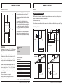
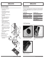
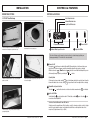
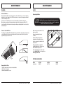
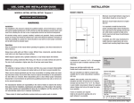
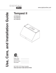
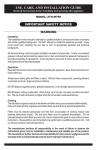
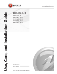
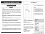
USE, CARE, AND INSTALLATION GUIDE
LIST OF MATERIALS
Read all Instructions before Installing and operating this appliance
MODELS: AK7000, AK7036, AK7042 Tempest I
IMPORTANT SAFETY NOTICE
WARNING
Installation
The installation in this manual is intended for qualified installers, service technicians or persons
with similar qualified background. DO NOT attempt to install this appliance yourself. Injury could
result from installing the unit due to lack of appropriate electrical and technical background.
All electrical wiring must be properly installed, insulated and grounded. Overly accumulated
grease in old duct work should be cleaned out or duct work should be replaced if necessary to
avoid the possibility of a grease fire. Check all joints on duct work to insure proper connection
and all joints should be properly taped.
Operations
Read all instructions in this manual before operating the appliance. Save these instructions for
future reference.
Always leave safety grills and filters in place. Without these components, operating blowers
could catch on to hair, fingers and loose clothing.
NEVER dispose cigarette ashes, ignitable substances, or any foreign objects into blowers.
NEVER leave cooking unattended. When frying, oil in the pan can easily overheat and catch fire.
The risk of self combustion is higher when the oil has been used several times.
Cleaning
The saturation of greasy residue in the blower and filters may cause increased inflammability.
Keep unit clean and free of grease and residue build-up at all times to prevent possible fires.
Filters must be cleaned periodically and free from accumulation of cooking residue (see cleaning instructions inside). Old and worn filters must be replaced immediately. Do not operateblowers when filters are removed. Never disassemble parts to clean without proper instructions.
Disassembly is recommended to be performed by qualified personnel only. Call our service center for removal instructions.
The manufacturer declines all responsibility in the event of failure to observe the instructions given here for installation, maintenance and suitable use of the product. The manufacturer further declines all responsibility for injury due to negligence and the warranty of the
unit automatically expires due to improper maintenance.
* Please check for latest specification revisions before any custom work or cutouts.
1 - Hood
2 - Baffle filters (3-36”, 3-42”)
2 - Halogen light bulbs (pre installed)
1 - Hardware packet containing:
4 - 2” drywall screws
4 - 1 1/2” drywall screws
4 - 1” drywall screws
4 - 1/2” washers
3 - wire connectors
1 - 6 to 3 1/4 x 10 rectangular transicion adapter
INSTALLATION
INSTALLATION
MOUNT HEIGHTS
DUCTING
Minimum mount height between range top to
hood bottom should be no less than 24".
10"
Min 24"-Max 32"
WARNING FIRE HAZARD
Maximum mount height should be no higher
than 32".
NEVER exhaust air or terminate duct work into spaces between walls, crawl spaces, ceiling,attics or
garages. All exhaust must be ducted to the outside.
It is important to install the hood at the
proper mounting height. Hoods mounted too
low could result in heat damage and fire hazard; while hoods mounted too high will be
hard to reach and will loose its performance
and efficiency.
Use metal ductwork only.
Fasten all connections with sheet metal screws and tape all joints w/ certified Silver Tape or Duct Tape.
Some Ducting Options:
96"
If available, also refer range manufacturer's
height clearance requirements and recommended hood mounting height above range.
36"
Side wall cap
w/ gravity damper
Side wall cap
w/ gravity damper
DUCTING
A minimum of 6" round or 3-1/4” x 10"rectangular
duct must be used to maintain maximum air flow
efficiency.
Soffit or crawl space
Minimum Duct Size:
Round:
6" minimum
Rectangular:
3-1/4” x 10”
Always use rigid type metal ducts only.
Flexible ducts could restrict air flow by up to 50%.
Also use calculation (on right) to compute total
available duct run when using elbows, transitions
and caps.
ALWAYS, when possible, reduce the number or
transitions and turns. If long duct run is required,
increase duct size from 6" to 7 or 8". If a reducer
is used, install a long reducer instead of a pancake
reducer. Reduce duct size as far away from opening as possible.
If turns or transitions are required:
Install as far away from opening and as far
apart, between 2, as possible.
Roof Pitch w/
Flashing & Cap
Duct Run Calculation:
Maximum run
6" or 3-1/4” x 10" duct
Deduct:
each 90 Elbow used
each 45 elbow used
each 6" to 3/14 x 10"
transition used
each 3/14 x 10" to 6"
each 3/14 x 10" to 6"
transition used
Side Wall Cap w/ damper
Roof Cap
100 FT
15 FT
9 FT
Rear Ducting
1 FT
5 FT
30 FT
30 FT
e.g.- 1 roof cap, 2x90 elbows, 1 x 45 elbow used:
=30' + 30' + 9' =69' used, 31' available for straight duct runs.
Models: AK7000, AK7036, AK7042 Page 1
Models: AK7000, AK7036, AK7042
Page 2
INSTALLATION
INSTALLATION
MOUNTING THE RANGEHOOD
SPECIFICATIONS
ELECTRICAL
12"
WARNING
TOP VIEW
1/2" Elec K.O.
10"
1"
4-1/2"
1-1/8"
8-5/8"
4"
Electrical Supply:
This appliance requires a 120V 60Hz electrical supply., and connected to an individual, properly
grounded branch circuit, protected by a 15 or 20 ampere circuit breaker or time delay fuse. Wiring
must be 2 wire w/ ground. Please also refer Electrical Diagram labeled on product.
36"
22"
TOP VIEW
1"
Cable Lock:
A cable locking connector (not supplied) might also be required by local codes. Check with local
requirements and codes, purchase and install appropriate connector if necessary.
REAR VIEW
1/2" Elec K.O.
10"
CL
4-1/2"
1-1/8"
3-1/4"
3-1/4"
8-5/8"
All Electrical work must by performed by qualified electrician or person with similar technical
1/2"and
Elec background.
K.O.
know how
CL
For personal safety, remove house fuse
or open circuit breaker before beginning installation.
3-1/4"
Do 3-1/4"
not use extension cord or adapter plug with
this appliance.
10"
Follow National electrical codes or10"prevailing local codes
and ordinances.
10"
30"
" Elec K.O.
REAR VIEW
10"
10"
10"
Cable Lock
Models: AK7000, AK7036, AK7042
Page 3
Models: AK7000, AK7036, AK7042
Page 4
INSTALLATION
INSTALLATION
MOUNTING THE RANGEHOOD
CONVERTIBLE OPTIONS
1. This range hood is mounted under a
kitchen cabinet unit.
2. Select preferred duct location on rear or
top of unit. (See page 6 & 7 for ducting
conversion options)
3. Begin installation by temporarily removing
the baffle filters.
4. Reinforce cabinet base with 1x2 wood
strips if additional strengthening is
required.
5. Temporarily position the range hood in
the desired mounting location.
Measure and mark the mounting holes,
duct and electrical access locations with
a pencil.
6. Drill/cut out the required openings for
duct and electrical access; make sure the
duct opening is large enough to apply
duct tape.
7. Fasten hood onto cabinet with screws
and washers provided.
8. Install electrical.
9. Install duct work and duct-tape.
10. Reinstall the baffle filters.
11. Power up hood and check for leaks
around duct-tape.
This range hood is equipped with the option of a 6” vertical discharge, 3 1/4”x10” vertical discharge,
or 3 1/4”x10” rear discharge. Additional accessories are provided to convert to either of the above
discharge methods.
Convertible Options
Vertical discharge
Vertical discharge
Horizontal rear discharge
Convertible Accesories
6” round
3 1/4”x10”
3 1/4”x10”
Round to rectangular transition adaptor
Rectangular to round transition adaptor (pre-mounted)
Gasket (pre-mounted)
Rectangular rear cap (pre-mounted)
3 1/4”x10” starting collar
3 1/4”x10” Vertical Discharge
6. Duct
opening
cutout
duct/silver
tape
4. Add 1x2
wood strips
1. Remove pre-mounted 6” transition adaptor or duct
opening. Leave attached gasket in its original place.
2. Place rectangular transition adaptor as shown over
gasket and by first installing 4 screws on half round
section.
3. Baffle
filters
3. Mount the 3-1/4”x10” starting collar on top of
transition piece with remaining screws.
Models: AK7000, AK7036, AK7042
Page 5
Models: AK7000, AK7036, AK7042
Page 6
INSTALLATION
CONTROLS & FEATURES
CONVERTIBLE OPTIONS
CONTROLS & FEATURES
3 1/4”x10” Rear Discharge
Auto Mode Indicator
Manual Mode Indicator
Lights On/Off Indicator
AUTO
MANUAL
1 Blower On/Off
6 Speed Level Indicator
1. At rear of range hood, remove all screws on premounted rear rectangular cap and remove cap.
2. Remove top pre-mounted transition piece. Leave
attached gasket in its original place.
2 Manual Mode Speed Selection
3 Lights On/Off/Dim
The control features on this range hood are touchless; to activate simply position your
finger approximately 1/4” in front of the selected switch.
1 Blower On/Off
AUTO
By pressing
, the blower is switched On and Off. When switched on, the blower starts up on
speed level 6 in auto mode AUTO , and will automatically adjust the fan speed accordingly.
While in auto mode AUTO , the manual AUTO
mode
indicator icon will flash indicating that you can
still manually change speeds by selecting the
or
controls.
MANUAL
MANUAL
MANUAL
AUTO
3. Mount rectangular transition piece at opening with
gasket as shown.
MANUAL
AUTO
MANUAL
MANUAL
Standby Mode
4. Mount rectangular cap (previously removed) on top
of transition adaptor.
If the range hood was in auto mode AUTO prior to shutdown, and detects any heat from below, the
blower will switch back on in auto mode AUTO to speed level 6 and then adjust itself accordingly.
MANUAL
MANUAL
2 Manual Mode Speed Selection
Selecting
AUTO
MANUAL
or
overides all auto mode controls and activates manual AUTO
mode
AUTO
MANUAL
as indicated.
MANUAL
3 Lights On/Off/Dim
AUTO
MANUAL
Switch lights On
by selecting this switch. To Dim lights, activate
MANUAL
MANUAL
AUTO
more time, will turnAUTO
lights Off.
again. Selecting
one
Touchless Controls Manual Power Off Switch
Should you wish to manually turn off the touchless control for cleaning or safety, an electric toggle
switch is located inside the range hood (behind the baffle filters on the right hand side of the
range hood) Toggle between I (on) or 0 (off).
5. Mount starting collar (provided) at rear discharge
opening with gasket.
Models: AK7000, AK7036, AK7042
Page 7
Models: AK7000, AK7036, AK7042
Page 8
MAINTENANCE
MAINTENANCE
CLEANING
LIGHTS
Surface Maintenance:
Replacing Light Bulbs
Clean periodically with hot soapy water and clean cotton cloth. Do not use corrosive or abrasive
detergent (e.g. comet powder scrub, EZ-Off oven cleaner), or steel wool/scoring pads which will
scratch and damage surface.
For heavier soil use liquid degreaser such as 'Formula 409' or 'Fantastic' brand cleaner.
After cleaning, you may use non abrasive stainless steel polish/ cleaners such as 3M or ZEP,
to polish and buff out the stainless luster and grain. Always scrub lightly, with clean cotton cloth,
and with the grain.
Stainless Steel Baffled Filters
The stainless steel baffled filters fitted by the factory are intended to trap residue and grease from
cooking. Although the filters never need replacement, they are required to be kept clean after
approximately every 30 hours of use.
CAUTION: Light bulb becomes extremely hot when turned on.
DO NOT touch bulb until switched off and cooled. Touching hot
bulbs could cause serious burns.
Make sure all power is turned off and
bulbs are not hot.
Remove by turning bulb counter
clockwise.
If bulbs are difficult to turn due to
prolonged use, firmly attach a glass
suction cup approx. the diameter of the
bulb and turn.
Replacement bulbs are available at
specialty lighting stores. Purchase type
GU10 120V 50W halogen bulbs.
Or to order bulbs, please call our service
center: 888-880-8368 or online parts store:
www.zephyronline.com
1
2
OPTIONAL ACCESSORIES
3
Model:
Back Splash
Removing Baffled Filters
AK7000
AK0710
AK7036
AK0716
AK7042
AK0712
1. Pull filter toward back of range hood using handles.
2. Pivot filter front upward.
3. Remove downwards to the rear.
Models: AK7000, AK7036, AK7042
Page 9
Models: AK7000, AK7036, AK7042
Page 10
WARRANTY
TO OBTAIN SERVICE UNDER WARRANTY:
You must present proof of original purchase date.
Please keep a copy of your dated proof of purchase (sales slip)
in order to obtain service under warranty.
TO OBTAIN SERVICE UNDER WARRANTY
or any Service Related Questions, please call:
1-888-880-8368
One Year Service Repair Warranty:
For one year from date of original purchase, we will provide free of charge, service labor to repair
any failed parts or components due to manufacturing defects.
Have your product proof of purchase with date ready for warranty issues.
Or write to:
Two Years Parts Warranty:
For two years from date of original purchase, we will provide free of charge, nonconsumable
replacement parts or components that failed due to manufacturing defects.
Consumable parts not covered by this warranty include: Light Bulbs, Metal and Carbon Filters.
Who is Covered:
This warranty is extended to the original purchaser for products purchased for ordinary
home use in the 48 mainland states, Hawaii and Washington D.C.
In Canada and Alaska, this warranty is Limited. There might be costs associated with shipping
the products to our designated service locations or you might need to pay service technician's
travel costs, to have the appliance repaired in-home.
This Warranty will be Voided when:
Product damaged through negligence, misuse, abuse, accident.
Improper installation and failure to follow installation instructions. When product is used
commercially or other than its intended purpose.
Damaged because of improper connection with equipment of other manufacturers.
Repaired or modified by anyone other than Zephyr's Authorized Agents.
What is Not Covered:
Consumable parts such as light bulbs, filters, and fuses.
Services outside of service area and the labor cost incurred in connection with the removal,
shipping and reinstallation cost, nor does it cover any other contingent expenses.
The natural wear of finish, and wear due to improper maintenance, use of corrosive and
abrasive cleaning products, pads, and oven cleaner products.
Chips, dents or cracks due to abuse, misuse, freight damage, or improper installation.
Service trips to your home to teach you how to use the product.
Damage of product caused by accident, fire, floods or act of God.
This warranty is valid in the United States and Canada. It is non-transferable and applies only to the original purchaser and
does not extend to subsequent owners of this product. Any applicable implied warranties, including the warranty of merchantability, are limited in duration to a period of express warranty as provided herein beginning with the date of original purchase at retail and, no warranties, whether express or implied, shall apply to this product thereafter.
Models: AK7000, AK7036, AK7042 Page 11
Zephyr Corporation
Service and Warranty Department
395 Mendell Street
San Francisco, CA 94124
Troubleshooting Procedures for AK7500, AK700
Issue
Cause
After installation, the unit
doesn’t work?
1. The power source is not turned ON.
1. Make sure the circuit breaker and the
unit’s power is ON.
2. The power line and the cable locking
connector is not connecting properly.
2. Check the power connection with the
unit is connected properly.
3. The switch board and control board
wirings are disconnected.
3. Make sure the wirings between the switch
board and control board are connected
properly.
4. On the switch board, Black/White wire or
White wire is disconnected.
4. Make sure the Black/White wire or White
wire connects properly.
5. The switch board or control board is
defective.
5. Change the switch board or control board.
1. The motor is defective, possible seized.
1. Change the motor.
2. The thermally protected system detects
if the motor is too hot to operate and
shuts the motor down.
2. The motor will function properly after the
thermally protected system cool down.
3. Damaged condenser.
3. Change the condenser.
4. The Blue wire on the control board is
disconnected.
4. Make sure the Blue wire on control board
is connected properly.
1. The motor is not secure in place.
1. Tighten the motor in place.
2. Damaged blower wheel.
2. Change the blower wheel.
3. The hood is not secured in place.
3. Check the installation of the hood.
1. Defective halogen bulb.
1. Change the halogen bulb.
2. The light bulb is loose.
2. Tighten the light bulb.
3. The RED wire on control board is
loosen.
3. Make sure the RED wire on control board is
connected properly.
1. The hood might be hanging to high from
the cook top.
1. Adjust the distance between the cook top
and the bottom of the hood within 24” and
32” range.
2. The wind from the opened windows or
opened doors in the surrounding area
are affecting the ventilation of the hood.
2. Close all the windows and doors to eliminate
the outside wind flow.
3. Blocking in the duct opening or duct
work.
3. Remove all the blocking from the duct work
or duct opening.
4. The direction of duct opening is
against the wind.
4. Adjust the duct opening direction.
5. Using the wrong size of ducting.
5. Change the ducting to at least 8” or higher.
1. Power on the heat lamp is not
turning on.
1. Make sure the heat lamp power is ON.
2. Heat lamp bulb is defective.
2. Change the heat lamp bulb.
3. Heat lamp bulb is loose.
3. Tighten the heat lamp bulb.
1. Metal filter is loose.
1. Change the metal filter.
2. Spring clip is broken.
2. Change the spring clip.
1. The right upper corner of LCD display
indicates “HI”.
1. Change the sensor.
2. The right upper corner of LCD display
indicates “LO”.
2. Change the sensor.
Light works, but motor is
not turning.
The unit is vibrating.
The motor is working,
but the lights are not.
The hood is not venting
out properly.
Heat lamp is not working.
Metal filter is vibrating.
Temperature Sensor is
not working.
What to do
3. The right upper corner of LCD display
3. Change the switch board.
indicates “Err” after changing the Sensor.