1
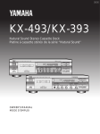
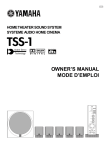
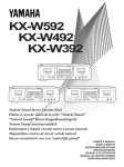
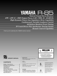
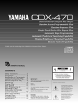
U
KPA-502
DIGITAL KARAOKE PROCESSING AMPLIFIER
AMPLIFICATEUR KARAOKE / D.S.P.
OWNER'S MANUAL
MODE D’EMPLOI
CONTENTS
TABLE DES MATIERES
CAUTION ............................................................................ 3
FEATURES .......................................................................... 4
ACCESSORY ....................................................................... 4
CONNECTIONS .................................................................. 5
CONTROLS AND THEIR FUNCTIONS ................................ 7
BASIC OPERATION ............................................................ 8
VARIOUS FUNCTIONS FOR KARAOKE PLAY ................. 10
REMOTE CONTROL TRANSMITTER ................................ 11
TROUBLESHOOTING ....................................................... 12
SPECIFICATIONS ............................................................. 12
ATTENTION .......................................................................
PARTICULARITES .............................................................
ACCESSOIRES .................................................................
RACCORDEMENTS ..........................................................
LES COMMANDES ET LEURS FONCTIONS ....................
OPERATIONS DE BASE ....................................................
FONCTIONS DIVERSES POUR L’UTILISATION EN
KARAOKE ......................................................................
BOITIER DE TELECOMMANDE ........................................
DETECTION DE PANNES .................................................
CARACTERISTIQUES .......................................................
13
14
14
15
17
18
Thank you for purchasing this unit.
To make full and effective use of this unit, please read this
Owner's Manual carefully before operating the unit.
After reading, retain this booklet for future reference.
Merci pour avoir acheté cet appareil.
Afin de pouvoir utiliser complètement et efficacement cet
appareil, lire ce mode d’emploi attentivement avant de faire
fonctionner l’appareil.
Après avoir l’avoir lu, conserver ce mode d’emploi comme
référence future.
20
21
22
22
SAFETY INSTRUCTIONS
CAUTION
RISK OF ELECTRIC SHOCK
DO NOT OPEN
CAUTION: TO REDUCE THE RISK OF ELECTRIC
SHOCK, DO NOT REMOVE COVER (OR BACK).
NO USER-SERVICEABLE PARTS INSIDE. REFER
SERVICING TO QUALIFIED SERVICE PERSONNEL.
÷ Explanation of Graphical Symbols
The lightning flash with arrowhead symbol,
within an equilateral triangle, is intended to
alert you to the presence of uninsulated
“dangerous voltage” within the product's
enclosure that may be of sufficient magnitude
to constitute a risk of electric shock to persons.
The exclamation point within an equilateral
triangle is intended to alert you to the presence
of important operating and maintenance
(servicing) instructions in the literature
accompanying the appliance.
WARNING
TO REDUCE THE RISK OF FIRE OR ELECTRIC
SHOCK, DO NOT EXPOSE THIS APPLIANCE TO RAIN
OR MOISTURE.
1 Read Instructions — All the safety and operating
instructions should be read before the unit is operated.
2 Retain Instructions — The safety and operating
instructions should be retained for future reference.
3 Heed Warnings — All warnings on the unit and in the
operating instructions should be adhered to.
4 Follow Instructions — All operating and other instructions
should be followed.
5 Water and Moisture — The unit should not be used near
water — for example, near a bathtub, washbowl, kitchen
sink, laundry tub, in a wet basement, or near swimming
pool, etc.
6 Carts and Stands — The unit should be used only with a
cart or stand that is recommended by the manufacturer.
6A A unit and cart combination
should be moved with care. Quick
stops, excessive force, and uneven
surfaces may cause the unit and cart
combination to overturn.
7 Wall or Ceiling Mounting — The unit should be mounted
to a wall or ceiling only as recommended by the
manufacturer.
8 Ventilation — The unit should be situated so that its
location or position does not interfere with its proper
ventilation. For example, the unit should not be situated on a
bed, sofa, rug or similar surfaces that may block the
ventilation openings: or placed in a built-in installation, such
as a bookcase or cabinet that may impede the flow of air
through the ventilation openings.
9 Heat — The unit should be situated away from heat
sources such as radiators, stoves, or other units that
produce heat.
10 Power Sources — The unit should be connected to a
power supply only of the type described in the operating
instructions or as marked on the unit.
11 Power-Cord Protection — Power-supply cords should
be routed so that they are not likely to be walked on or
pinched by items placed upon or against them, paying
attention to receptacles, and the point where they exit from
the unit.
12 Cleaning — The unit should be cleaned only as
recommended by the manufacturer.
13 No Use Periods — The power cord of the unit should be
unplugged from the outlet when left unused for a long
period of time.
14 Object and Liquid Entry — Care should be taken so
that objects do not fall into and liquids not spilled into the
inside of the unit.
15 Damage Requiring Service — The unit should be
serviced by qualified service personnel when:
A. The power-supply cord or the plug has been damaged;
or
B. Objects have fallen, or liquid has been spilled into the
unit; or
C. The unit has been exposed to rain; or
D. The unit does not appear to operate normally or exhibits
a marked change in performance; or
E. The unit has been dropped, or the cabinet damaged.
16 Servicing — The user should not attempt to service the
unit beyond those means described in the operating
instructions. All other servicing should be referred to
qualified service personnel.
17 Power Lines — An outdoor antenna should be located
away from power lines.
18 Grounding or Polarization — The precautions should be
taken so that the grounding or polarization of the unit is not
defeated.
IMPORTANT!
Please record the serial number of this unit in the space
below.
Model:
Serial No.:
2
The serial number is located on the rear of the unit.
Retain this Owner’s Manual in a safe place for future
reference.
CAUTION: READ THIS BEFORE OPERATING
YOUR UNIT.
FCC INFORMATION (U.S.A.)
1. IMPORTANT NOTICE: DO NOT MODIFY THIS UNIT!
This product, when installed as indicated in the
instructions contained in this manual, meets FCC
requirements. Modifications not expressly approved by
Yamaha may void your authority, granted by the FCC, to
use the product.
2. IMPORTANT: When connecting this product to
accessories and/or another product use only high quality
shielded cables. Cables supplied with this product
MUST be used. Follow all installation instructions.
Failure to follow instructions could void your FCC
authorization to use this product in the USA.
3. NOTE: This product has been tested and found to
comply with the requirements listed in FCC Regulations,
Part 15 for Class "B" digital devices. Compliance with
these requirements provides a reasonable level of
assurance that your use of this product in a residential
environment will not result in harmful interference with
other electronic devices. This equipment generates/uses
radio frequencies and, if not installed and used
according to the instructions found in the users manual,
may cause interference harmful to the operation of other
electronic devices. Compliance with FCC regulations
does not guarantee that interference will not occur in all
installations. If this product is found to be the source of
interference, which can be determined by turning the unit
"OFF" and "ON", please try to eliminate the problem by
using one of the following measures:
Relocate either this product or the device that is being
affected by the interference.
Utilize power outlets that are on different branch (circuit
breaker or fuse) circuits or install AC line filter/s.
In the case of radio or TV interference, relocate/reorient
the antenna. If the antenna lead-in is 300 ohm ribbon
lead, change the lead-in to coaxial type cable.
If these corrective measures do not produce satisfactory
results, please contact your local retailer that is
authorized to distribute this type of product. If you
cannot locate the appropriate retailer, please contact
Yamaha Electronics Corp., U.S.A.
6660 Orangethorpe Ave, Buena Park, CA 90620
The above statements apply ONLY to those products
distributed by Yamaha Corporation of America or its
subsidiaries.
We Want You Listening For A Lifetime
YAMAHA and the Electronic Industries Association's
Consumer Electronics Group want you to get the most out of
your equipment by playing it at a safe level. One that lets the
sound come through loud and clear without annoying blaring
or distortion – and, most importantly, without affecting your
sensitive hearing.
Since hearing damage from loud sounds
is often undetectable until it is too late,
YAMAHA and the Electronic Industries
Association's Consumer Electronics
We
Want You
Group recommend you avoid prolonged
LISTENING
For A Lifetime
exposure to excessive volume levels.
1. This unit is a sophisticated stereo amplifier. To ensure proper
operation for the best possible performance, please read this
manual carefully.
2. Choose the installation location of your unit carefully. Avoid
placing it in direct sunlight or close to source of heat. Also
avoid locations subject to vibration and excessive dust, heat,
cold or moisture. Keep it away from sources of hum such as
transformers or motors.
3. Do not open the cabinet as this may result in damage to the
unit or electrical shock. If a foreign object should get into the
unit, contact your local dealer.
4. When removing the power plug from the wall outlet, always
pull directly on the plug; never pull the cord itself.
5. Do not apply excessive force when operating switches and
knobs.
6. When moving the unit, be sure to first pull out the power plug
and remove all cords connecting the unit to other equipment.
7. Do not attempt to clean this unit with chemical solvents as
this may damage the finish. Use a clean, dry cloth.
8. Always set the VOLUME control to “∞” before playing the
source. Increase the volume gradually to a desired level after
the source has started playing.
9. When not planning to use this unit for long periods of time
(e.g., vacation, etc.), disconnect the AC power plug from the
electrical outlet.
10. Do not connect audio equipment to the AC outlet on the rear
panel if the equipment requires more power than the outlet is
rated to provide.
11. The openings on the cabinet assure proper ventilation of the
unit. If these openings are obstructed, the temperature inside
the cabinet will rise rapidly, damaging the unit or causing a
fire. Avoid blocking the ventilation openings and make sure
that the unit is well ventilated. Allow at least 5 cm (2 in) of
space above and behind the unit and at least 3 cm (1-1/4 in)
of space to the left and right of the unit.
12. Be sure to read the “TROUBLESHOOTING” section of this
manual for advice on common operating errors before
concluding that your unit is faulty.
13. Keep this manual in a safe place for future reference.
14. Voltage Selector (General and China model only)
The voltage selector on the rear panel of this unit must
be set for your local mains voltage BEFORE plugging in
the AC mains supply. (Voltage selector adjustable
between 110/120/220/240 V AC 50/60 Hz)
FOR CANADIAN CUSTOMERS
TO PREVENT ELECTRIC SHOCK, MATCH WIDE
BLADE OF PLUG TO WIDE SLOT AND FULLY
INSERT.
THIS CLASS B DIGITAL APPARATUS MEETS ALL
REQUIREMENTS OF THE CANADIAN
INTERFERENCE-CAUSING EQUIPMENT
REGULATIONS.
3
FEATURES
÷ Three audio inputs (VCD/LD, TAPE and AUX),
two video inputs (VCD/LD and AUX) and two
video outputs (MONITOR OUT 1 and 2) allow
you to connect various audio/video
components.
÷ Combination of three different Echo controls
(VOLUME, REPEAT, DELAY) gives various
echo effects to voices through the
microphones.
÷ Digital Key Control function allows you to
select the desired musical pitch.
(±2 note, 9 steps)
ACCESSORY
After unpacking, check that the following accessories are
supplied.
Remote control transmitter
KARAOKE
VCD/LD
TAPE
AUX
MPX/
STEREO
ONE TOUCH
KARAOKE
VOCAL AID
KARAOKE
DSS
I
BALLAD
POPS
JAZZ
ROCK
È
–
i
+
VOLUME
÷ With Sound Multiplex sources, the volume of
the original vocals and the music can be
adjusted by using the MPX BALANCE
control.
÷ MUSIC VOL control lets you balance your
vocals and the music by adjusting the music
volume level.
÷ VOCAL AID replaces the original vocals with
your voice when you sing.
÷ The built in KARAOKE DSS sound field
processor has four different settings
(BALLAD, POPS, JAZZ, and ROCK) to let you
obtain the desired atmosphere according to
the music type.
÷ ONE TOUCH KARAOKE lets you cut the
original vocals from general stereo sources
so they can be used as karaoke sources.
÷ Your karaoke play can be recorded with a
cassette deck connected to this unit.
÷ High-power built-in amplifier
What are the Sound multiplex sources?
With a Sound Multiplex tape designed for karaoke use or a
sound multiplex disc (laser karaoke disc, etc.), generally,
the right channel contains both background music and
original vocals, and the left channel contains only
background music.
Thus, these sources allow you to select only the
background music, or to adjust the volume between
original vocals and music by rotating the MPX BALANCE
control.
Note:
There are also other types of karaoke sources, with
which the sound adjustments of this unit may not function
properly. Please confirm the type is the karaoke source
you have purchased, before reproducing it with this unit.
4
Batteries (size AA, R6, UM-3)
CONNECTIONS
÷ Be sure to disconnect power cords of all the audio and
video components from the AC outlets. Do not turn the
power on until all connections are completed.
÷ When making connections between this unit and other
components, make sure that all connections are correct,
L (left) to L, R (right) to R.
Cassette deck
Output
Input
VCR
VCD/LD/CD player
Audio output
Video output
(For VCD or LD)
Audio
output
Video
output
General model
VOLTAGE
SELECTOR
AC OUTLETS
UNSWITCHED
100W MAX. TOTAL
AUDIO SIGNAL
PRE
OUT
TAPE
VCD/LD
PLAY
AUX
VIDEO SIGNAL
VDC/LD
Power cord
\
SPEAKERS
6
AUX
REC
+
Ω MIN./SPEAKER
R
—
—
L
+
GND
L
To an AC
outlet
R
1
3
4
1
2
MONITOR OUT
See next page.
Line input
Subwoofer
Video
input
Monitor 1
Video
input
Monitor 2
Right
*1
Left
Speakers
(For connections to the
SPEAKERS terminals,
see the next page.)
For powerful sound
To reproduce a more powerful sound, connect a power
amplifier (instead of a subwoofer) to the PRE OUT jacks to
drive high-power speakers.
*1 GND terminal
Usually, it is not necessary to make a connection to this
terminal. However, when excessive noise exists, connect
the GND terminals of this unit and other components to
minimize the noise.
5
Connecting speakers
Connecting the AC OUTLETs
Connect the SPEAKERS terminals to your speakers with
wire of the proper gauge cut as short as possible. If the
connections are faulty, no sound will be heard from the
speakers. Make sure that the polarity (+ and – markings) of
the speaker wires are correct. If these wires are reversed,
the sound will be unnatural and will lack bass. Do not let
bare speaker wires touch each other and do not let them
touch the metal parts of this unit as this could damage this
unit and/or speakers.
÷ Use speakers with an impedance of 6 ohms or more.
Using speakers with an impedance of less than 6
ohms may result in malfunction or damage to this
amplifier.
÷ Do not connect more than one pair in parallel to this
amplifier.
This unit is equipped with two UNSWITCHED AC OUTLETs
for connecting the power cords of other components to this
unit.
The power to these outlets is not controlled with this unit’s
POWER switch. They will continuously supply power to any
component connected to them.
The total maximum power consumption of components
connected to these outlets must not exceed 100 watts.
1
2
3
Press down the tab.
Insert the bare wire. [Remove approx. 5mm insulation
from the speaker wires.]
Raise the tab to secure the wire.
Black: Negative (–)
L +
+ R
2
Red: Positive (+)
1
6
3
CONTROLS AND THEIR FUNCTIONS
1
2
3
4
5
6
7
8
9
DIGITAL KARAOKE PROCESSING AMPLIFIER KPA 502
VOLUME
16
20
ECHO VOL
KARAOKE DSS
POWER
BALLAD
POPS
JAZZ
INPUT
ROCK
VCD/LD
MPX/STEREO ONE TOUCH KARAOKE
TAPE
12
MUSIC VOL
28
VOCAL AID
8
AUX
40
4
DIGITAL KEY CONTROL
I4
I3
I2
I1
È
# 1
# 2
# 3
# 4
60
MIN
MIN
MAX
2
MAX
∞
0
— dB
MUSIC
BASS
—
p
ECHO
TREBLE
+
q
—
+
w
MIC
REPEAT
MIN
MAX
e
DELAY
MIN
MPX BALANCE
MAX
MUSIC
r
1 POWER button
Press this button to turn the power on or off.
2 KARAOKE DSS buttons / indicators (BALLAD, POPS,
JAZZ, ROCK)
Press one of these buttons to obtain a suitable effect for
the corresponding music type.
VOCAL
t
BALANCE
L
LEVEL 1
MIN
R
y
u
LEVEL 2
MAX
MIN
MAX
i
MIC 1
MIC 2
KEY
CONTROL
o
;
p DIGITAL KEY CONTROL buttons / indicators
Use these buttons to obtain the desired musical pitch.
q MUSIC BASS control
Adjusts the music tone of low frequency sound.
w MUSIC TREBLE control
Adjusts the music tone of high frequency sound.
3 INPUT selector (VCD/LD, TAPE, AUX)
Press one of these buttons to select the input signal.
e ECHO REPEAT control
Adjusts the repeating number of the echo.
4 MPX/STEREO button / indicator
Press this button when playing the sound multiplex
karaoke disc or tape.
5 ONE TOUCH KARAOKE button / indicator
Press this button to reduce the level of the original
vocals when playing a stereo source.
6 VOCAL AID button / indicator
Press this button to replace original vocals with your
voice when singing a karaoke song.
r ECHO DELAY control
Adjusts the echo length.
t MPX BALANCE control
Adjusts the volume level between the original vocals and
music when playing a sound multiplex source.
y BALANCE control
Adjusts the balance between the left and right speakers.
u Remote control sensor
7 ECHO VOL control
Receives the signals emitted from the remote control.
Adjusts the echo level.
i MIC LEVEL controls (1, 2)
8 MUSIC VOL control
Adjust the microphone level.
Adjusts the music volume.
o MIC jacks (1, 2)
9 VOLUME control
Connect a microphone.
Adjusts the volume.
; KEY CONTROL jack
Connect the key control plug of the microphone to
control the music pitch with the microphone.
7
BASIC OPERATION
1
2 3-A 3-B 4
5
DIGITAL KARAOKE PROCESSING AMPLIFIER KPA 502
VOLUME
16
20
ECHO VOL
KARAOKE DSS
BALLAD
POWER
POPS
JAZZ
INPUT
ROCK
VCD/LD
MPX/STEREO ONE TOUCH KARAOKE VOCAL AID
TAPE
12
MUSIC VOL
28
8
60
2
AUX
40
4
DIGITAL KEY CONTROL
I4
I3
I2
I1
È
# 1
# 2
# 3
# 4
MIN
MIN
MAX
MAX
∞
0
— dB
MUSIC
BASS
—
ECHO
TREBLE
+
—
+
MIC
REPEAT
MIN
MAX
DELAY
MIN
MPX BALANCE
MAX
MUSIC
VOCAL
BALANCE
L
LEVEL 1
MIN
R
MAX
LEVEL 2
MIN
MIC 1
MIC 2
KEY
CONTROL
MAX
Connect the microphone(s) to
the MIC jack(s) and turn on the
microphone(s).
1
B When playing a stereo source (general CDs or
Turn on the power of this unit.
music tapes with vocals, etc.)
Make sure that the MPX/STEREO button is set to
off. (The indicator goes off.)
POWER
2
Press the ONE TOUCH KARAOKE button so
that the indicator lights.
Select the source to be played with the INPUT
selector and start playback.
(Adjust the VOLUME control to the appropriate level.)
ONE TOUCH KARAOKE
INPUT
VCD/LD
TAPE
The volume of the original vocals is reduced and
the music is mainly heard.
With some discs, however, the original vocals
may remain heard.
AUX
3 A When playing the sound multiplex source
4
Adjust the microphone level with the MIC LEVEL
control(s) while speaking into the microphone(s).
(sound multiplex karaoke disc or tape, etc.)
MIC
LEVEL 2
LEVEL 1
Press the MPX/STEREO button so that the
indicator lights.
MPX/STEREO
MIN
MAX
MIN
MAX
(For best results keep knobs set close to the center
position.)
«
5
Adjust the MPX BALANCE control.
To decrease the volume level of the original
vocals, turn the control toward "MUSIC".
To decrease the volume level of the music, turn
the control toward "VOCAL".
MPX BALANCE
MUSIC
VOCAL
Re-adjust the overall volume with the VOLUME
control.
VOLUME
16
20
12
28
8
60
2
40
4
∞
0
— dB
When howling (a high-pitched sound) occurs
Separate the microphone farther away from the speakers,
decrease the microphone level, or lower the overall volume
level with the VOLUME control.
Notes on the microphone
When the microphone is not being used, turn off the
microphone switch or unplug the microphone.
8
MUSIC BASS and TREBLE
ECHO VOL
MUSIC VOL
DIGITAL KARAOKE PROCESSING AMPLIFIER KPA 502
VOLUME
16
20
ECHO VOL
KARAOKE DSS
BALLAD
POWER
POPS
JAZZ
INPUT
ROCK
VCD/LD
MPX/STEREO ONE TOUCH KARAOKE VOCAL AID
TAPE
12
MUSIC VOL
28
8
60
2
AUX
40
4
DIGITAL KEY CONTROL
I4
I3
I2
I1
È
# 1
# 2
# 3
# 4
MIN
MIN
MAX
MAX
∞
0
— dB
MUSIC
BASS
—
ECHO
TREBLE
+
—
+
MIC
REPEAT
MIN
MAX
DELAY
MIN
MPX BALANCE
MAX
ECHO REPEAT
MUSIC
VOCAL
BALANCE
L
R
ECHO DELAY
To adjust the balance between the left and right
speakers
Turn the BALANCE control towards "R" to move the sound
image to the right. To move the sound image to the left,
turn the control towards "L".
LEVEL 1
MIN
MAX
LEVEL 2
MIN
MIC 1
MIC 2
KEY
CONTROL
MAX
BALANCE
Adding the echo effect to your voice
The ECHO VOL, ECHO DELAY and ECHO REPEAT controls
are used to adjust the echo effect.
To adjust the echo level
Turning the ECHO VOL control towards "MAX" increases the
echo level, while turning the control towards "MIN"
decreases it.
BALANCE
ECHO VOL
L
R
To adjust only the music volume
Turn the MUSIC VOL control towards "MAX" to increase the
volume level of the input source other than the microphones
volume. To decrease it, turn the control towards "MIN".
MIN
MAX
MUSIC VOL
To adjust the echo length
Turning the ECHO DELAY control towards "MAX" expands
the echo length, while turning the control towards "MIN"
shortens it.
ECHO
MIN
DELAY
MAX
To adjust only the music tone
For high frequency sound
Turning the MUSIC TREBLE control towards "+" increases
the level, while turning the control towards "–" decreases
the level.
For low frequency sound
Turning the MUSIC BASS control towards "+" increases
the level, while turning the control towards "–" decreases
the level.
MIN
MAX
To adjust the repeating number of the echo
Turning the ECHO REPEAT control towards "MAX" increases
the repeating number of the echo, while turning the control
towards "MIN" decreases it.
ECHO
REPEAT
MUSIC
BASS
TREBLE
MIN
—
+
—
+
MAX
÷ The voices heard through the microphones have the
same echo effect.
÷ If the sound is distorted by increasing the music tone
level, turn down the MUSIC VOL control.
÷ The voices cannot be adjusted with these controls.
9
VARIOUS FUNCTIONS FOR KARAOKE PLAY
BALLAD
POPS
JAZZ
ROCK
VOCAL AID
DIGITAL KARAOKE PROCESSING AMPLIFIER KPA 502
VOLUME
16
20
ECHO VOL
KARAOKE DSS
POWER
BALLAD
POPS
JAZZ
INPUT
ROCK
VCD/LD
MPX/STEREO ONE TOUCH KARAOKE VOCAL AID
TAPE
12
MUSIC VOL
28
8
60
2
AUX
40
4
DIGITAL KEY CONTROL
I4
I3
I2
I1
È
# 1
# 2
# 3
# 4
MIN
MIN
MAX
MAX
∞
0
— dB
MUSIC
BASS
—
ECHO
TREBLE
+
—
+
MIC
REPEAT
MIN
MAX
DELAY
MIN
MPX BALANCE
MAX
MUSIC
VOCAL
BALANCE
L
R
LEVEL 1
MIN
MAX
LEVEL 2
MIN
DIGITAL KEY CONTROL
To replace original vocals with your voice
when you sing
Press the VOCAL AID button so that the indicator lights.
When you sing into the microphone, your voice replaces the
original vocals.
MIC 1
MIC 2
KEY
CONTROL
MAX
KEY CONTROL jack
To obtain the desired musical pitch
Use the DIGITAL KEY CONTROL buttons to obtain the
desired musical pitch (±2 note, 9 steps). The DIGITAL KEY
CONTROL indicators (±4 and normal indicators) display the
selected pitch.
To return to the
normal pitch
To heighten the pitch
To lower the pitch
VOCAL AID
DIGITAL KEY CONTROL
I4
÷ When playing the sound multiplex sources with the MPX
setting of the MPX/STEREO button, adjust the MPX
BALANCE control to balance the volume between original
vocals and music.
To obtain an atmosphere according to the
music type
Press one of the buttons to select the suitable effect for the
music type you sing.
KARAOKE DSS
BALLAD
POPS
JAZZ
ROCK
BALLAD: Suitable for mellow songs with slow-tempo; you
can sing with expressions.
POPS:
Suitable for pop music; you can sing with lightfeelings.
JAZZ:
Provides the reflections like in a small hall,
which give an atmosphere similar to a jazz club.
ROCK:
Suitable for dynamic and rhythmical rock
sound.
Press the same button again to cancel the effect.
÷ This function has effect on both of the background music
and the sound through the microphone.
10
I3
I2
I1
È
i1
i2
i3
i4
NOTES:
÷ If the input signal is interrupted for about 4 seconds, the
setting will returns to the normal pitch.
÷ If another button of the INPUT selector is pressed, the
musical pitch returns to the normal pitch.
Controlling the musical pitch with microphone
It is also possible to control the musical pitch with the
microphone provided with the key control plug (available in
some areas).
Connect the microphone to the MIC 1 or MIC 2 jack, and
insert its key control plug in the KEY CONTROL jack next to
the MIC jack.
To record karaoke play
Karaoke play can be recorded with the cassette deck
connected to this unit. Before recording, set the INPUT
selector to the VCD/LD or AUX position according to the
source to be played.
NOTES:
÷ During playback of the cassette deck, the input signal of
the TAPE PLAY jacks and your voices are not output from
the TAPE REC jacks. Thus, you cannot record that
signals even when other cassette decks are connected.
÷ The settings of MUSIC BASS, MUSIC TREBLE and
DIGITAL KEY CONTROLs, etc. are reflected to the
recorded sound. Therefore, the recorded sound will be
similar to the sound output from the speakers.
REMOTE CONTROL TRANSMITTER
With the remote control transmitter provided with this unit,
you can operate the unit at your listening/singing position.
The buttons on the remote control transmitter have the same
functions as those with the identical names on the main unit.
For detailed instructions, refer to the descriptions on the
corresponding buttons on the main unit.
Battery installation
1
Pull out the battery compartment lid in the direction of
the arrow.
2
Install the batteries (size AA, R6, UM-3) with correct
polarities. Follow the diagram in the compartment.
3
Push the compartment lid in until it clicks into place.
KARAOKE
Karaoke
function buttons
VCD/LD
TAPE
AUX
MPX/
STEREO
ONE TOUCH
KARAOKE
VOCAL AID
BALLAD
POPS
JAZZ
ROCK
È
i
KARAOKE
DSS
I
VOLUME buttons
+: press to turn
up volume
–: press to turn
down volume
—
+
Input selector
buttons
2
KARAOKE DSS
buttons
DIGITAL KEY
CONTROL buttons
VOLUME
1
3
Battery replacement
If you find that the remote control transmitter must be used
closer to the main unit, the batteries are weak. Replace
both batteries with new ones.
REMOTE CONTROL OPERATION RANGE
REMOTE SENSOR
NOTES:
÷ Use only AA, R6, UM-3 batteries for replacement.
÷ Be sure that the polarities are correct. (See the illustration
inside the battery compartment.)
÷ Remove the batteries if the remote control transmitter will
not be used for an extended period of time.
÷ If batteries leak, dispose of them immediately. Avoid
touching the leaked material or letting it come in contact
with clothing, etc. Clean the battery compartment
thoroughly before installing new batteries.
∞
6m
30°
30°
11
TROUBLESHOOTING
If this unit functions abnormally during operation, first check the following items. If the unit continues to function abnormally, or
if an abnormality occurs other than those listed below, switch off the unit's power and disconnect the AC plug, and then
consult your authorized YAMAHA dealer or servicing personnel.
SYMPTOM
REMEDY
POSSIBLE CAUSE
Microphone plug is not firmly inserted
to the jack.
Insert firmly.
Microphone is turned off.
Turn on the power of the microphone.
The MIC LEVEL is set to MIN
Set the MIC LEVEL to an appropriate level.
The volume of the original
vocals cannot be reduced
even when the MPX
BALANCE control is turned to
the MUSIC side.
The MPX/STEREO button is not set
properly.
With sound multiplex sources, set the MPX/
STEREO button to on. (The indicator lights.)
Your voice cannot replace the
original vocals even when the
ONE TOUCH KARAOKE
button is pressed.
The volume level of the microphone
is low.
Turn up the volume of the microphone with the
MIC LEVEL control.
The singing voice level is not loud
enough.
Sing louder.
The sound of the playback
source is not heard.
The INPUT selector is not set
properly.
Set it to the source to be played.
It happens that this unit does
not work normally
There is an influence of strong
external noise (lightning, excessive
static electricity, etc.) or a
misoperation was performed while
using this unit.
Turn this unit power off and disconnect the AC
power from the AC outlet. After about 30
seconds have passed, connect the power and
try again.
Your voice is not heard
through the microphone.
NOTE:
When the unit fails to operate normally because of some reasons, turn the power on and off by pressing the POWER button.
The microcomputer inside the unit is reset through this procedure.
SPECIFICATIONS
<Audio>
Minimum RMS Output Power per Channel ..... 75W + 75W
(0.05% THD, 20Hz~20kHz, 6 ohms, both channels driven)
Rated Output RMS Power (EIAJ) ................. 100W + 100W
Input Sensitivity/Impedance
MIC ........................................................ 1.0 mV/30 kohms
VCD/LD, TAPE, AUX ............................. 150 mV/50 kohms
Output Level/Impedance (Input Level: 150 mV)
PRE OUT ....................................................... 1 V/1 kohms
REC OUT ................................................ 150 mV/1 kohms
Music Tone Control Characteristic
BASS (Boost/Cut) ............................ +9 dB/–9 dB (50 Hz)
TREBLE (Boost/Cut) ...................... +8 dB/–8 dB (10 kHz)
<Video>
Video Input Level/Impedance
VCD/LD, AUX ......................................... 1 Vp-p/75 ohms
Video Output Level/Impedance
MONITOR 1, 2 ......................................... 1Vp-p/75 ohms
<General and China model>
Power Supply .................. AC 110/120/220/240 V, 50/60 Hz
Power Consumption ................................................. 145 W
AC Outlet (2 UNSWITCHED OUTLETS) ... 100 W max. total
(U.S.A. model)
Power Supply ............................................ AC 120 V, 60 Hz
Power Consumption ................................................. 140 W
AC Outlet (2 UNSWITCHED OUTLETS) ... 100 W max. total
(Singapore model)
Power Supply ............................................ AC 230 V, 50 Hz
Power Consumption ................................................. 145 W
AC Outlet (2 UNSWITCHED OUTLETS) ... 100 W max. total
Dimensions (W x H x D) ...................... 420 x 141 x 434 mm
Weight ...................................................................... 10.4 kg
Specifications are subject to change without notice.
12
YAMAHA
YAMAHA
YAMAHA
YAMAHA
YAMAHA
YAMAHA
YAMAHA
ELECTRONICS CORPORATION, USA 6660 ORANGETHORPE AVE., BUENA PARK, CALIF. 90620, U.S.A.
CANADA MUSIC LTD. 135 MILNER AVE., SCARBOROUGH, ONTARIO M1S 3R1, CANADA
ELECTRONIK EUROPA G.m.b.H. SIEMENSSTR, 22-34, 25462 RELLINGEN, BEI HAMBURG, F.R. OF GERMANY
ELECTRONIQUE FRANCE S.A. RUE AMBROISE CROIZAT BP70 CROISSY-BEAUBOURG 77312 MARNE-LA-VALLEE CEDEX02, FRANCE
ELECTRONICS (UK) LTD. YAMAHA HOUSE, 200 RICKMANSWORTH ROAD WATFORD, HERTS WD1 7JS, ENGLAND
SCANDINAVIA A.B. J A WETTERGRENS GATA 1, BOX 30053, 400 43 VASTRA FRÖLUNDA, SWEDEN
MUSIC AUSTRALIA PTY, LTD. 17-33 MARKET ST., SOUTH MELBOURNE, 3205 VIC., AUSTRALIA
Printed in Malaysia
V203450