1
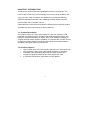
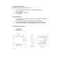
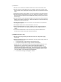
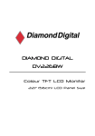
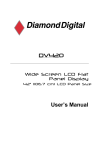
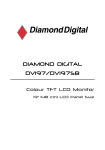
DIAMOND DIGITAL DX-D191P Colour TFT LCD Monitor 19” (43 cm) LCD Panel Size Copyright 2008, Mitsubishi Electric Australia Pty. Ltd. All rights reserved. No part of this publication may be reproduced, transmitted, transcribed, stored in a retrieval system or translated into any language or computer language, in any form or by any means, electronic, mechanical, magnetic, optical, chemical, manual or otherwise, without the prior written permission. IMPORTANT SAFETY INSTRUCTIONS ...................................... iii Disclaimer .......................................................................................... iv CHAPTER 1 INTRODUCTION....................................................... 5 1.1 Product Description ............................................................... 5 1.2 Product Features .................................................................... 5 1.3 Package Contents .................................................................. 6 1.4 Product Care........................................................................... 6 1.5 Product Dimension................................................................. 6 1.6 Caution .................................................................................... 6 CHAPTER 2 OPERATION INSTRUCTIONS ................................. 9 2.1 Front Control Panel ................................................................ 9 2.2 OSD Menu ............................................................................. 10 2.3 OSD Function Table ............................................................. 12 2.4 Input Signal Icon................................................................... 14 2.5 Hot Key Icon ......................................................................... 14 CHAPTER 3 SIGNAL CONNECTOR AND INSTRUCTION......... 15 Input / Output Interface .............................................................. 15 CHAPTER 4 VIEWING ANGLE ................................................... 16 CHAPTER 5 PANEL SPECIFICATION ........................................ 19 i CHAPTER 6 WARRANTY ........................................................... 20 After Sales Service ..................................................................... 20 Warranty Does NOT Cover: ....................................................... 20 Service Contacts ........................................................................ 21 ii IMPORTANT SAFETY INSTRUCTIONS 1. Read these instructions. 2. Keep these instructions. 3. Heed all warnings. 4. Follow all instructions. 5. Do not use this apparatus near water. 6. Clean only with dry cloth. 7. Do not block any ventilation openings. Install in accordance with the manufacturer’s instructions. 8. Do not install near any heat sources such as radiators, heat registers, stoves, or other apparatus (including amplifiers) that produce heat. 9. Protect the power cord from being walked on or pinched particularly at plugs, convenience receptacles, and the point where they exit from the apparatus. 10. Only use attachments/accessories specified by the manufacturer. 11. Use only with the cart, stand, tripod, bracket, or table specified by the manufacturer, or sold with the apparatus. When a cart is used, use caution when moving the cart/apparatus combination to avoid injury from tip-over. 12. Unplug this apparatus during lightning storms or when unused for a long period of time. 13. Refer all servicing to qualified service personnel. Servicing is required when the apparatus has been damaged in any way, such as power-supply cord or plug is damaged, liquid has been spilled or objects have fallen into the apparatus, the apparatus has been exposed to rain or moisture, does not operate normally, or has been dropped. 14. WARNING: To reduce the risk of fire or electric shock, do not expose this apparatus to rain or moisture. 15. Apparatus shall not be exposed to dripping or splashing and no objects filled with liquids, such as vases, shall be placed on the apparatus. iii Disclaimer Mitsubishi Electric Australia Pty. Ltd. makes no representations or warranties, either expressed or implied, with respect to the contents hereof and specifically disclaims any warranties, merchantability or fitness for any particular purpose. Further, Mitsubishi Electric Australia reserves the right to revise this publication and to make changes from time to time in the contents hereof without obligation to notify any person of such revision or changes. Diamond Digital is a registered trademark of Mitsubishi Electric Australia Pty. Ltd. Microsoft and Windows are registered trademarks of Microsoft Corporation. All other trademarks remain the property of their respective owners. Reference Information For future reference, write the following information about your monitor in the space below. The serial number is found on the back of the product or on the bottom of its stand. Monitor Information Product Name: Diamond Digital DX-D191P Serial Number: Date of Purchase: Dealer Information Dealer: Telephone Number: Address: iv CHAPTER 1 INTRODUCTION Thank you for choosing the Diamond Digital DX-D191P LCD monitor. Your LCD monitor is safe to use and completely free from any X-ray radiation. We hope you enjoy using our product, and would like to provide the following additional information to assist you in obtaining the best results, using the product safely and in complete comfort. Please follow ALL instructions and cautions carefully before using this product. And keep this user manual handy for future reference. 1.1 Product Description This product uses a 19" colour active matrix TFT (thin-film transistor) LCD panel with a protective screen, providing high quality displayed images. The maximum supported resolution is 1280 x 1024, which enables the display of complex and high quality images. In addition, the monitor also provides access to OSD (On Screen Display) controls and has built in multi-media speakers, and BNC (Composite) input and output ports. 1.2 Product Features High contrast colour TFT LCD monitor, supports VGA / DVI signal input up to resolution 1280 x 1024, video signal resolution up to 500TVL. Imbedded video signal BNC terminal and S-Video terminal and component signal RCA terminal and Audio signal RCA Jack. A complete OSD function optimizes the screen display. 5 1.3 Package Contents Standard package includes the following: 1. 2. 3. 4. 19" TFT LCD Monitor. (Depend on the screen diagonal) Power Adapter. Signal Cable. (VGA Cable) User Manual. 1.4 Product Care 1. To remove dust or dirt from the screen, use a soft clean cotton cloth and wipe gently. 2. Do not apply pressure to the screen surface while wiping. 3. Do not use any water or chemical detergent to clean the surface. Chemicals detergent may damage the surface of the LCD panel. 1.5 Product Dimension 1.6 Caution 6 ● PRODUCT 1. Do not cover or block the ventilation holes in the back of the monitor case. 2. Do not insert any metal objects into the ventilation holes of the monitor case and be careful not to spill liquids over this product as this could result in severe injury. 3. Unplug the monitor’s power cable if it’s not to be used for a long period of time. 4. Do not attempt to dismantle this product. Any attempt to dismantle or remove the covers from this product will invalidate the warranty and may also result in serious injury. 5. Do not touch the screen directly with fingers. The oils from your skin may leave marks on the surface of the screen, which are difficult to be removed and may damage the screen permanently. 6. Do not apply pressure to the LCD screen. The LCD panel is a very delicate and fragile component. 7. AC Adapter holder can be dismounted when not in use. 8. When a standard base is not used, for safety concern, please use the M4 screws with flat washers and spring washers provided, length between 8 ~ 10mm. 9. If enclosed standard base is not to be used, any base assembled to the monitor should meet VESA 100 x 100mm standards. ● MAINS PLUG (2Pin / 3Pin) 1. Do not remove the grounding or earth connection from the power supply / mains plug. 2. Always remember to unplug the LCD Monitor from the power supply under the following circumstances: If the monitor will not be used for a long period of time. If the power supply cable or plug / connector is damaged. (Please refer to the “User Manual “when connecting and disconnecting the LCD Monitor from any power supply or other systems and before making any adjustments to the Monitor. In the event of any unexpected situation occurring whilst operating the Monitor please switch off the power supply and remove the power cable. If the problem is not explained in the User Manual, please contact your local dealer or our customer service department.) If the monitor housing is damaged or broken. 7 ● POWER CORD AND SIGNAL CABLE 1. Do not place anything on the power cord or signal cable. 2. Do not allow any cables from the monitor to lie on the floor in an area where pedestrians are likely to trip, causing injury. 3. This product is supplied with a 3 line-grounding plug. The grounding plug provides an additional safety feature for anyone using this equipment and should not be removed. Please contact a qualified electrician for assistance if the grounding plug and electrical connections appear to differ from the local supply provided. Do NOT discard the safety-grounding plug. 4. Do not overload the power cord or adapter. 5. Do not place the power cord or signal cable in a humid area. ● ALLOCATION ENVIRONMENT 1. DO NOT place this product on any unstable trolleys, shelves or tables as it may fall and cause severe injury and damage. 2. Always ensure that the monitor is located in a well-ventilated area to prevent the unit from overheating. 3. AVOID operating or placing the monitor in the following environments: Extremes of temperatures, both hot and cold. High Humidity. Direct sunlight. Excessively Dusty Surroundings. Avoid close proximity to other equipment that generates a strong magnetic field. 8 CHAPTER 2 OPERATION INSTRUCTIONS 2.1 Front Control Panel 1. Power Switch: press to switch monitor on / off. 2. LED Indicator: power indicator. 3. Mode: press to select input signal. (See ※ Note) 4. Auto: VGA signal auto adjustment. 5. Plus (+): press to increase the value of OSD option selected; press to increase volume. 6. Minus (-): press to decrease the value of OSD option selected; press to decrease volume. 7. Up (Contrast): select OSD options upwards; press to adjust contrast. 8. Down (Brightness): select OSD options downwards; press to adjust brightness. 9. Menu: recall or close OSD display, enter or return selection. 9 ※ Note: On the first press, the monitor shows OSD of the current signal. Before the OSD disappears, press the button again to change the input signal source. 2.2 OSD Menu ● VGA / DVI Signal ※ ※ ※ ※ 1. 2. 3. 4. 5. 6. 7. 8. 9. 10 11. 12. 13. 14. 15. 16. 17. Brightness Contrast H-Position V-Position Clock Phase Colour Temp. User Colour R User Colour G User Colour B OSD H-Pos. OSD V-Pos. Volume PIP PIP Size/Pos. Language Recall 26 25 25 32 25 1 User Colour 51 51 51 25 25 10 Off DEF. Hot Key English Item 3,4,5,6 have different value after auto tuning, but can’t be adjusted in DVI mode. Above Value / data is for reference only. 10 ● VIDEO (Composite / S-Video / Component) Signal ※ 1. 2. 3. 4. 5. 6. 7. 8. 9. 10 11. 12. 13. Colour Tint Brightness Contrast Sharpness Volume H-Position Language Colour Temp. Scan PIP PIP Size/Pos. Recall 30 26 26 25 4 10 25 English Standard Over Off DEF. Hot Key ※ The Colour Temp. Dependent on the region. Above Value / data is for reference only. 11 2.3 OSD Function Table ● VGA / DVI 1. 2. 3. 4. 5. 6. Brightness Contrast H-Position V-Position Clock Phase 7. Colour Temp. 8. 9. 10. 11. 12. 13. User Colour R User Colour G User Colour B OSD H-Pos. OSD V-Pos. Volume 14. PIP 15. PIP Size/Pos. 16. Language 17. Recall Adjust back ground black level of the screen image. Adjust fore ground white level of the screen image. Adjust the left or right position of the screen image. Adjust the up or down position of the screen image. Adjust the horizontal sync width of the screen image. Adjust the clarity of the screen image. Press (+) or (-) to choose three types of colour temperature 9300°K , 6500°K , User Colour. Adjust the red colour’s intensity of the screen image. Adjust the green colour’s intensity of the screen image. Adjust the blue colour’s intensity of the screen image. Adjust the left or right position of the OSD. Adjust the up or down position of the OSD. Adjust the volume control. View the video input screen image on the left-top screen. Press (+) or (-) to choose four types of PIP: Composite, S-Video, Component, Off. (1) PIP Size: Adjust PIP size by (+) or (-). (2) PIP Position: Adjust PIP position by up、down、 (+) and (-). (3) DEF. Hot Key: Switch to initial hot key function. Select languages: English, Chinese, French, German, Spanish, Italian or Japanese. Press (+) or (-) recall the default value. 12 ● VIDEO (Composite / S-Video / Component) 1. 2. 3. 4. 5. 6. 7. Colour Tint Brightness Contrast Sharpness Volume H-Position 8. Language 9. Colour Temp. 10. Scan 11. PIP 12. PIP Size/Pos. 13. Recall Adjust the colour density. Adjust the colour tint. (NTSC only) Adjust back ground black level of the screen image. Adjust fore ground white level of the screen image. Adjust the clarity and focus of the screen image. Adjust the volume control. Adjust the left or right position of the screen image. Select languages: English, Chinese, French, German, Spanish, Italian or Japanese. Press (+) or (-) to choose three types of colour temperature 9300°K , 6500°K , Standard. Press (+) or (-) to choose four type of over scan or under scan or full scan or 1: 1 scan. View the video input screen image on the left-top screen. Press (+) or (-) to choose four types of PIP: VGA, DVI, Off. (1) PIP Size: Adjust PIP size by (+) or (-). (2) PIP Position: Adjust PIP position by up、down、 (+) and (-). (3) DEF. Hot Key: Switch to initial hot key function. Press (+) or (-) recall the default value. 13 2.4 Input Signal Icon VGA Signal DVI Signal Composite Signal S-VIDEO Signal Component Signal 2.5 Hot Key Icon Volume Adjustment Contrast Adjustment Brightness Adjustment 14 CHAPTER 3 SIGNAL CONNECTOR AND INSTRUCTION Input / Output Interface 1. DC In 2. DC Out: DC 12V / MAX. 1A. 3. VGA In 4. VIDEO In / Out (BNC-TYPE) 5. Y/C In / Out (4-Pin mini-Din) S-Video 6. Audio In / Out (RCA Jack) If you choose a video input without connecting any video signal, “No Signal" will be displayed onto the screen. If a video cable is disconnected while the display is being used, “Video Loss " will be displayed onto the screen. Note: ※ It takes about 2 ~ 3 seconds to switch between modes. ※ When Mode is changed, the monitor will show a blue screen, then display the selected input or display " NO Signal ". 15 Caution: AVOID directly pulling any cables, when disconnecting devices from the monitor. Always disconnect devices carefully by firmly gripping the metal or plastic connector body and gently easing the connector from its socket. CHAPTER 4 VIEWING ANGLE For the user’s convenience, the LCD screen may be tilted according to viewing requirements. The monitor can be tilted forward up to 5 degrees or backward up to 40 degrees. 16 ● RAK191 - RACK MOUNTING BRACKET【OPTIONAL】 ● CM191 - CEILING MOUNTING BRACKET【OPTIONAL】 17 ● WB-191 - WALL MOUNTING BRACKET【OPTIONAL】 ● Base Dismounting Process (Step 1) Remove the Hinge Cover (1-1) Insert a thin tool into the hole of the hinge cover, then pull upward and outward to remove the cover. . (1-2) Pull the cover outward 4~5 mm as indicated by arrow A, then pull the cover upward as indicated by arrow B, then remove the cover. (Step 2) Remove screws (4 pcs) and base 18 CHAPTER 5 PANEL SPECIFICATION Please refer to attach specification sheet. MODEL 19" Pixel pitch (H x V mm) 0.294 x 0.294. VGA / DVI Max. Resolution VIDEO 1280 x 1024 pixels. Dimension (W x H x D mm) Packing Dimension (W x H x D mm) Display Mode Signal Connector Front Control Panel Buttons 500TVL. 421.2 x 405.6 x 170.0 553.0 x 534.0 x 242.0 VGA、DVI、Composite、S-VIDEO、Component. DC In/Out, VGA In, DVI In【OPTION】, BNC In/Out, Y/C In/Out, Y Cb Cr In【OPTION】, Audio In/Out. Power Switch, LED Indicator, Mode, Auto, Plus (Volume Increase), Minus (Volume Decrease), Up (Contrast Adjust), Down (Brightness Adjust), Menu. VGA / DVI Brightness, Contrast, H-Position, V-Position, Clock, Phase, Colour Temp., User Colour R.G.B, OSD H-Pos., OSD V-Pos., Volume, PIP, PIP Size/Pos., Language, Recall. VIDEO Colour, Tint (NTSC only), Brightness, Contrast, Sharpness, Volume, H-Position, Language, Colour Temp., Scan, PIP, PIP Size/Pos., Recall. OSD Menu Power Input DC Input: 12V / Above 4A. Power Output DC Output: 12V / 1A. Operating Condition Temp. : 0°C ~ 40°C, Humidity: 20% ~ 85%. Storage Condition Temp. : -20°C ~ 60°C, Humidity: 20% ~ 85%. Power Consumption 50W. (Max.) N.W. Weight (adapter included) 6.1kgs. G.W. 8.4kgs. 19 CHAPTER 6 WARRANTY After Sales Service After this product is unpacked, keep the carton and packing materials to ensure safe transportation in case of any after sales service. The warranty is covered by a 3 year limited warranty, subject to normal conditions of use. If you experience any problems with this product please contact your local dealer or supplier for repair and maintenance instructions. Warranty Does NOT Cover: ※ Any damage resulting from incorrect use or careless operation or handling of the equipment. ※ Any damage caused by not operating the equipment in accordance with the manufacturer’s instructions detailed in the " User Manual " . ※ Any tampering or removal of the Monitor housing will invalidate the warranty. ※ Damages resulting from natural disasters e.g. flood, fire and earthquake. ※ Any damages caused by inappropriate transportation or storage of the equipment. 20 Service Contacts Australian Service Contacts Visit the Customer Support page of Mitsubishi Electric Australia’s web site at; www.mitsubishielectric.com.au Further details of your nearest Mitsubishi Electric Authorized Service Center or to contact a Mitsubishi Electric Service Representative in your state or territory: New South Wales and Australian Capital Territory 348 Victoria Road Rydalmere, NSW, 2116 Telephone: (02) 1300 651-808 Fax: (02) 9684-7684 Queensland 12 / 468 Nudgee Road Hendra, QLD, 4011 (Airlink Business Park) Telephone: (07) 3623-2000 Fax: (07) 3630-1888 21 South Australia and Northern Territory 77 Port Road Hindmarsh, SA, 5007 Telephone: (08) 8340-0444 Fax: (08) 8340-0555 Victoria and Tasmania 4 / 303 Burwood Hwy East Burwood, VIC, 3151 Telephone: (03) 9262-9899 Fax: (03) 9262-9850 Western Australia 5 / 329 Collier Road Bassendean, WA, 6054 Telephone: (08) 9377-3411 Fax: (08) 9377-3499 22