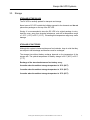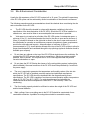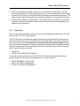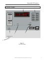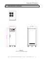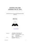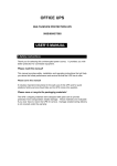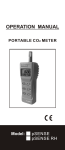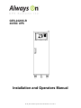
1
GES-242NX-R
24VDC UPS
Installation and Operators Manual
M1306_GES-242NX-R Operators and Install Manual V1.0 2012-06-12
Always On UPS Systems
M1306_GES-242NX-R Operators and Install Manual V1.0 2012-06-12
Always On UPS Systems
Table of Contents
1.
2.
3.
CAUTION .................................................................................................................................... 1
IMPORTANT SAFETY INSTRUCTIONS ............................................................................... 2
UNPACKING .............................................................................................................................. 5
3.1.
Transport ............................................................................................................................. 5
3.2.
Delivery ................................................................................................................................ 5
3.3.
Storage................................................................................................................................. 6
3.4.
Site & Environment Consideration .................................................................................. 7
3.5.
Unpacking ............................................................................................................................ 8
3.6.
Cable Selection................................................................................................................... 9
4.
80KVA DC UPS SYSTEMS LAYOUT DRAWINGS .......................................................... 10
5.
DC UPS WIRING DIAGRAMS............................................................................................... 11
6.
TERMINAL STRIP LAYOUT ................................................................................................. 13
7.
C-CHANNEL INSTALLATION .............................................................................................. 14
8.
OPERATION INSTRUCTIONS.............................................................................................. 15
9.
FRONT PANEL ........................................................................................................................ 16
10.
RELAY CONTACTS ................................................................................................................ 19
11.
DIMENSIONAL DRAWING .................................................................................................... 20
12.
CONTACT INFORMATION.................................................................................................... 21
M1306_GES-242NX-R Operators and Install Manual V1.0 2012-06-12
Always On UPS Systems
1. CAUTION
This is a manual for Installation purposes only.
Do not attempt the start up of the DC UPS or apply power to the input terminals.
Factory authorized personnel shall inspect installation prior to start up and commissioning to
validate warranty.
Failure to follow this directive will result in void warranty.
M1306_GES-242NX-R Operators and Install Manual V1.0 2012-06-12
1
Always On UPS Systems
2. IMPORTANT SAFETY INSTRUCTIONS
READ AND FOLLOW ALL SAFETY INSTRUCTIONS.
SAVE THESE INSTRUCTIONS.
This manual contains important safety instructions that should be followed during installation and
maintenance of the N Series DC UPS system and optional packages. Before the installation
process begins, we recommend that the installer read through the safety precautions, operators
manual and the option installation instructions, taking all necessary safety precautions to protect
themselves and the equipment being installed.
GENERAL
Move the DC UPS in an upright position, in its original packaging, to its final destination.
To lift the cabinets, use a forklift or lifting belts with spreader bars.
- Check for sufficient floor and elevator loading capacity.
- Check the integrity of the DC UPS equipment carefully.
If visible damage is evident, do not attempt to install or start the DC UPS. Contact the transport
delivery company immediately, file a claim with the transport company and inform Always On
directly.
- Do not use outdoors
- The use of accessory equipment not recommended by Always On may cause an unsafe
condition
- WARNING! RISK OF ELECTRICAL SHOCK: use extreme caution when removing covers.
- All maintenance and service work should be performed by qualified and trained service
personnel. The DC UPS may contain its own energy source, (batteries) which can be
dangerous to the untrained person. This DC UPS contains potentially hazardous voltages
- The field-wiring terminals may be electrically live, even when the DC UPS is not connected to
the utility.
- Use caution when servicing batteries. A battery can present a risk of electrical shock, burn from
high short-current. Battery acid can cause burns to skin and eyes. If acid is spilled on skin or in
eyes, flush with fresh water and contact physician immediately.
- When replacing batteries use the same number and type (sealed-cell lead acid).
- Proper disposal of batteries is required. Refer to your local codes for disposal requirements.
- Dangerous voltages may be present during battery operation. The batteries must be
disconnected during maintenance or service work. (Open battery breaker of fuses)
- Be aware that the inverter can restart automatically after the utility voltage is restored.
- Do not use this equipment for other than intended use.
M1306_GES-242NX-R Operators and Install Manual V1.0 2012-06-12
2
Always On UPS Systems
INSTALLATION
-
This DC UPS is intended for use in a controlled indoor environment free of conductive
contaminants and protected against any type of intrusion.
Do not install the DC UPS in an excessively humid environment or near water.
Avoid spilling liquids and/or dropping any foreign object(s) onto the DC UPS.
The unit must be placed in a sufficiently ventilated area; the ambient temperature should not
exceed 40°C (104°F).
Optimal battery life is obtained if the ambient temperature does not exceed 25°C (77°F).
HIGH GROUND LEAKAGE CURRENT: ground connection completed before connecting the
AC voltage wires on the input!
Switching OFF the DC UPS does not isolate the DC UPS from the utility as the utility supply is
still HOT at the input terminal strip. Supply breaker needs to be opened.
It is important that air can move freely around and through the unit. Do not block the air vents.
Avoid locations in direct sunlight or near heat sources (gas or electric heaters).
STORAGE
-
Store the DC UPS in a dry location free of contaminants;
Storage temperature must be within -25°C (-13°F) to 55°C (131°F).
If the unit is stored for a period exceeding 3 months, the batteries must be recharged
periodically (time depending on storage temperature).
WARNING!
LETHAL VOLTAGES MAY BE PRESENT WITHIN THIS UNIT EVEN WHEN IT IS APPARENTLY
NOT OPERATING. OBSERVE ALL CAUTIONS AND WARNINGS IN THIS MANUAL. FAILURE
TO DO SO COULD RESULT IN SERIOUS INJURY OR DEATH. REFER UNIT TO QUALIFIED
SERVICE PERSONNEL IF MAINTENANCE IS REQUIRED. NO ONE SHOULD WORK ON THIS
EQUIPMENT UNLESS THEY ARE FULLY QUALIFIED TO DO SO. AN INSTALLER SHOULD
NEVER WORK ALONE.
WARNING!
WHEN REMOVING POWER FROM THE DC UPS, ALLOW FIVE MINUTES FOR CAPACITORS
TO DISCHARGE BEFORE WORKING ON THE EQUIPMENT.
CAUTION!
This equipment complies with the requirements in Part 15 of FCC rules for a Class A
computing device. Operation of this equipment in a residential area may cause interference
to radio and TV reception, requiring the operator to take whatever steps necessary to
correct the interference.
CAUTION!
Do not put option control wiring in the same conduit as the DC UPS input or output power
cables.
M1306_GES-242NX-R Operators and Install Manual V1.0 2012-06-12
3
Always On UPS Systems
THIS SAFETY NOTICE IS ADDRESSED TO THE ALWAYS ON
CUSTOMER ENGINEERS WHO PERFORM MAINTENANCE OF THE
UNINTERRUPTIBLE POWER SUPPLY (UPS) SYSTEMS.
Electrical Safety
• Maintenance work to be preformed by factory trained customer engineers, or qualified
personnel. Extremely dangerous voltage levels can exist within the DC UPS system.
Extreme caution must be used.
• Ensure system is in maintenance DC UPS mode or external wrap-around DC UPS
mode before work is started.
• This manual is designed as an aid tool in diagnosing problems that may arise. Always
On does not assume responsibility if information causes injuries.
• Apart from the front door, do not open any other part of the DC UPS without consulting
the factory first. Before removing the protection screens, be sure that the unit is
completely powered off.
• Be aware that dangerous voltage can be supplied by the internal battery or electrolytic
capacitors.
• When system is in DC UPS mode and all fuses have been opened dangerous voltages
may exist within the DC UPS system. Use extreme caution when exchanging boards
and working inside the unit.
READ AND FOLLOW ALL SAFETY INSTRUCTIONS.
SAVE THESE INSTRUCTIONS.
M1306_GES-242NX-R Operators and Install Manual V1.0 2012-06-12
4
Always On UPS Systems
3. UNPACKING
3.1. Transport
The DC UPS is packaged on a pallet, suitable for handling with a forklift.
Pay strict attention to the center of gravity. The DC UPS must be moved in upright position. Do
not tilt cabinets more than +/- 10° during handling.
Move the DC UPS in its original package to the final destination site.
Do not stack other packages on top.
If the DC UPS must be lifted by crane, use suitable lifting straps and spreader bars.
3.2. Delivery
Upon receiving the DC UPS system, inspect the packaging integrity and the physical condition
of the cabinets carefully.
In the event that physical damage is visible, the carrier must be informed immediately and a
claim filed with them. Inform Always On as soon as the claim has been filed and a copy of claim
should be faxed to Always On at (250) 491-9775.
A detailed report of the damage is necessary for carrier insurance claim.
WARNING
A damaged DC UPS system must never be installed or connected to the utility or batteries
without written instruction from Always On Engineering.
M1306_GES-242NX-R Operators and Install Manual V1.0 2012-06-12
5
Always On UPS Systems
3.3. Storage
STORAGE OF THE DC UPS
The DC UPS is carefully packed for transport and storage.
Never leave a DC UPS outside the building exposed to the elements and do not
place other packages on the top of the DC UPS.
Storing: It is recommended to store the DC UPS in its original package in a dry,
dust-free room, away from chemical substances, and with a temperature range
of -25°C (-13°F) to 55°C (131°F). Exceeding this temperature range may cause
damage.
STORAGE OF BATTERIES
Although this system includes maintenance free batteries, keep in mind that they
are subject to self-discharge and therefore must be recharged.
The storage time without battery recharge depends on the temperature of the
storage site. The optimal temperature for battery storage is 20°C (68°F) to 25°C
(77°F).
Recharge of the stored maintenance free battery every:
6 months when the ambient storage temperature is 20°C (68°F)
3 months when the ambient storage temperature is 30°C (86°F)
2 months when the ambient storage temperature is 35°C (95°F)
M1306_GES-242NX-R Operators and Install Manual V1.0 2012-06-12
6
Always On UPS Systems
3.4. Site & Environment Consideration
Usually the life expectancy of the DC UPS system is 8 to 10 years. The optimal life expectancy
of the DC UPS system can be achieved by careful consideration of the site and environment.
The following precautions and recommendations should be checked when considering the site
and environment for the DC UPS:
a.
The DC UPS should be located in a place with adequate ventilation (refer to the
specification of the heat dissipation of the DC UPS). Should the DC UPS be installed in a
sealed room, care must be taken to ensure adequate heat evacuation is provided.
b.
Void space is not required on all sides of the DC UPS system, but adequate space, a
minimum of 1m (3’), should be allowed at the front for the door to open and a minimum of
60cm (2’) should be allowed on the right side to allow for the door to open and removal of
the side panels for operation or maintenance purposes (exceptions to space requirements
would occur with approved layouts). Adequate space, a minimum of 60cm (2’)
[recommended 1m (3’)], should also be allowed at the top of the DC UPS system to allow for
proper heat dissipation and ventilated through the top openings (optional ventilation booth is
available upon request).
c.
Do not place any objects on the top of the DC UPS that might obscure the ventilation. Do
not place the DC UPS near any heat source, or machinery, which may produce metallic
particles, dust or powder. Do not place the DC UPS near equipment that will produce
corrosive substances or vapor.
d.
Do not place the DC UPS below the shower of a fire extinguishing system (optional drip
shield available). Abnormal conditions of the DC UPS should be protected by a cutoff from
the power supply.
e.
The user is required to guarantee the temperature and humidity values of the site into
which the DC UPS will be installed, meet the required and published manufacturer
specifications. The DC UPS should be installed within the range allowed by these
specifications. The DC UPS is capable of continuous normal operation within a temperature
range of 0°C (32°F) to 40°C (104°F). For optimal performance and reliability the
recommended environment temperature is best at 25°C, with humidity < 80% noncondensing.
f.
The floor loading capacity should be sufficient to endure the weight of the DC UPS and
and its internal batteries.
g.
Walls, ceilings, floors or anything near to the DC UPS should be constructed of noncombustible materials. A portable fire extinguisher should be accessible nearby.
M1306_GES-242NX-R Operators and Install Manual V1.0 2012-06-12
7
Always On UPS Systems
h. Avoid accumulating litter or trash of any sort in or around the DC UPS system. The floor
area surrounding the DC UPS should be kept clean, free from metallic powder and/or filings.
i. Access to the DC UPS room should be limited to operation and maintenance personnel. The
doors should be kept locked and the keys should be available only to authorized personnel.
j.
Personnel who operate or maintain the DC UPS system should be proficient in normal and
emergency operational procedures. New personnel should be trained and qualified prior to
operation of the equipment.
3.5. Unpacking
Once in room of final destination, carefully remove all the packaging material from the DC UPS
and place the DC UPS in its final position.
This DC UPS system has passed all stages of production testing and final QC testing prior to
shipment from the factory (report enclosed). The DC UPS should be in full operating condition
upon receipt. Upon receiving visually check the DC UPS for any physical damage that may
have occurred during transport. If damage is noticed file a damage report immediately with the
transport company and inform Always On directly. Also check to ensure all of the accessories
and/or options ordered are received.
•
•
DOOR KEY
INSTALL AND OPERATOR’S MANUAL
Check and verify the specifications of the DC UPS are identical to the specifications of the
system ordered. The key items in the specifications you must check are:
•
•
•
RATED POWER OF THE DC UPS
INPUT VOLTAGE & FREQUENCY
OUTPUT VOLTAGE & FREQUENCY
M1306_GES-242NX-R Operators and Install Manual V1.0 2012-06-12
8
Always On UPS Systems
3.6. Cable Selection
The cabling of the DC UPS system has to be sized according to the UPS power rating.
Sizing of circuit breakers, fuses and cables for input utility, output load and battery must meet
the requirements of local and national electrical codes.
WARNING
Inadequate cable size and over sized breakers can increase the risk of fire or damage
connection cables and internal components.
M1306_GES-242NX-R Operators and Install Manual V1.0 2012-06-12
9
Always On UPS Systems
4. 24VDC UPS SYSTEMS LAYOUT DRAWINGS
DC OUTPUT
RECTIFIER
WARNING
LOW BAT
INPUT
BAT STOP
CHARGER
OUTPUT
FAULT
FLOAT
Figure 4.1
Front View of System with Door Open
Single Wide
M1306_GES-242NX-R Operators and Install Manual V1.0 2012-06-12
10
Always On UPS Systems
5. DC UPS WIRING DIAGRAMS
Figure 5.1
DC-UPS Single Line
M1306_GES-242NX-R Operators and Install Manual V1.0 2012-06-12
11
Always On UPS Systems
Figure 5.2
DC UPS Power Cabling Diagram
M1306_GES-242NX-R Operators and Install Manual V1.0 2012-06-12
12
Always On UPS Systems
6. TERMINAL STRIP LAYOUT
Figure 6.1
Terminal Strip Layout
M1306_GES-242NX-R Operators and Install Manual V1.0 2012-06-12
13
Always On UPS Systems
7. C-CHANNEL INSTALLATION
M1306
GES-242NX-R Operators and Install Manual
2/16/2009
Approved: Eng. Mgr. (T. Naito)
14
Always On UPS Systems
8. OPERATION INSTRUCTIONS
1.1. Startup Procedure
a. Turn ON the INPUT breaker.
b. Wait 5 seconds for the “Charger LED” to start flashing.
c. Turn ON the BATTERY breaker.
d. Turn ON the OUTPUT breaker.
1.2. Shutdown Procedure
a. Turn OFF the OUTPUT breaker.
b. Turn OFF the BATTERY breaker.
c. Turn OFF the INPUT breaker.
CAUTION: Batteries will become damaged upon
over-discharge. Upon “BATTERY STOP ALARM”,
shutdown loads and the DC UPS System.
M1306_GES-242NX-R Operators and Install Manual V1.0 2012-06-12
15
Always On UPS Systems
9. FRONT PANEL
B
Startup Procedure
1 Turn ON the
INPUT breaker.
2 Wait 5 seconds
for the “Charger
LED” to start
flashing.
3 Turn ON the
BATTERY
breaker.
4 Turn ON the
OUTPUT breaker.
Shutdown Procedure
1 Turn OFF the
OUTPUT breaker.
2 Turn OFF the
BATTERY
breaker.
3 Turn OFF the
INPUT breaker.
METERING
AC INPUT
VOLTAGE
F
C
DC OUTPUT
VOLTAGE
DC BATTERY
CURRENT
DC OUTPUT
CURRENT
D
ALARM SILENCE/
RESET
E
Figure 7.1
Front Panel Display
M1306_GES-242NX-R Operators and Install Manual V1.0 2012-06-12
16
Always On UPS Systems
A: Metering- The GES-242N-R incorporates 4 digital displays for the user to monitor
their Voltages and Currents.
1. Input AC voltage:
Detects the input AC, allowing the user to monitor the 480 VAC
required to power the UPS.
2. Battery Current:
This ammeter detects both charge and discharge current of the
batteries. The ammeter has a range of +/- 200 ADC.
3. DC Output Voltage: Detects the DC output voltage supplied to the Load.
4. DC Output Current: This ammeter detects the output current on the main bus bar.
The ammeter has a range of +/- 200 ADC.
METERING
DC OUTPUT
VOLTAGE
AC INPUT
VOLTAGE
DC BATTERY
CURRENT
DC OUTPUT
CURRENT
B: Warning LED’s-When an abnormal condition occurs, these LED’s will illuminate allowing the
user to identify the fault. This will also allow the service personnel the ability
to troubleshoot the system. These LED’s are described below:
•
•
•
•
•
•
•
INPUT – No AC Voltage is detected on the input of the UPS.
CHARGER - The LED will illuminate continuously when the charger fails
to deliver the necessary voltage to charge the batteries. The LED will
flash if the Battery Breaker is open.
FAULT - tells the operator that one or both DC rectifiers have failed and
to immediately shut the UPS down
BAT LOW - This alert is designed to inform the operator that the battery
voltage is below 22.0 VDC and serve as a reminder to shut the system
down if the UPS is no longer needed.
BAT LOW STOP – This alert is designed to inform the operator that the
battery voltage is below 20.5 VDC and that the UPS system should be
shut down immediately to prevent damage to the batteries.
OUTPUT - The output status indicator is designed to inform the operator
of the status of the output breaker. If the breaker is open the red LED will
illuminate. Once the breaker is closed, the LED will go out.
FLOAT – The Batteries are fully charged.
M1306_GES-242NX-R Operators and Install Manual V1.0 2012-06-12
17
Always On UPS Systems
C. Rectifier LED: This LED is lit when the rectifier is operating, the supply is within operating
parameters, and the input breaker is closed.
D. Output LED:
This LED is lit when there is DC power present at the output terminals.
E: Callback Switch:
Is installed to allow the user to silence the buzzer when a fault arises while
they are working on the unit. Once the system is repaired and functioning
properly the buzzer will re-activate letting the user know to put the toggle switch
back into the normal operating mode.
F: Buzzer outlet: There is a buzzer located behind the LCD Display. The buzzer will allow for a
continuous audile notification during an abnormal condition. The buzzer will
be activated under one of the following conditions: (During some conditions,
the buzzer is mutable. These functions are described for your reference.)
•
•
•
•
•
•
INPUT BREAKER IS OPEN
ABNORMAL CHARGER CONDITION
ABNORMAL RECTIFIER CONDITION
LOW BATTERY
BATTERY SHUTDOWN
OUTPUT BREAKER IS OPEN
Mutable
Un-Muteable
Un-Muteable
Mutable
Un-Muteable
Mutable
M1306_GES-242NX-R Operators and Install Manual V1.0 2012-06-12
18
Always On UPS Systems
10. RELAY CONTACTS
AC FAULT: Tells the end user that no AC Voltage is present
on the input of the DC UPS.
FAULT: Is designed to inform the operator when the charger
fails to deliver the necessary voltage to charge the batteries. It
is also designed to inform the operator that one or both DC
rectifiers have failed and that the DC UPS should be
immediately shut down.
LOW BATTERY: This alert is designed to inform the
operator that the battery voltage is below 22.0 VDC and serve
as a reminder to shut the system down if the UPS is no longer
needed.
BATTERY SHUTDOWN: This alert is designed to inform
the operator that the battery voltage is below 20.5 VDC and
that the DC UPS system should be shut down immediately to
prevent damage to the batteries.
NO OUTPUT: The output status indicator is designed to
inform the operator of the status of the output breaker.
M1306_GES-242NX-R Operators and Install Manual V1.0 2012-06-12
19
Always On UPS Systems
11. DIMENSIONAL DRAWING
Figure 8.1
24VDC DC UPS
Exterior
Figure
10.1 Layout
M1306
GES-242NX-R Operators and Install Manual
2/16/2009
Approved: Eng. Mgr. (T. Naito)
20
Always On UPS Systems
12. CONTACT INFORMATION
QA / Warranty Questions
Always On UPS Systems Inc.
1 – 150 Campion Road,
Kelowna, BC, Canada, V1X 7S8
Phone: (250) 491-9777 Ext 209
Fax: (250) 491-9775
Email: [email protected]
Website: www.alwayson.com
Software Questions
Always On UPS Systems Inc.
1 – 150 Campion Road,
Kelowna, BC, Canada, V1X 7S8
Phone: (250) 491-9777 Ext 204
Fax: (250) 491-9775
Email: [email protected]
Website: www.alwayson.com
Additional Purchases or Upgrades
Always On UPS Systems Inc.
1 – 150 Campion Road,
Kelowna, BC, Canada, V1X 7S8
Phone: (250) 491-9777 Ext 451
Fax: (250) 491-9775
Email: [email protected]
Website: www.alwayson.com
M1306
GES-242NX-R Operators and Install Manual
2/16/2009
Approved: Eng. Mgr. (T. Naito)
21